


SETUP & |
OPERATION MANUAL |
||||
|
|
|
|
|
|
New! Upper and lower blade guard |
SCROLL SAW |
||||
FEATURES |
|
|
|
|
|
assembly helps prevent unintentional or |
|
|
|
|
|
accidental hand/finger contact with the |
|
|
|
|
|
saw blade |
|
|
|
|
|
New! Switch protection device to prevent |
|
|
|
|
|
accidental or unintentional start-up of the |
|
|
|
|
|
saw. |
|
|
|
|
|
New! Dust collector table kit for direct |
|
|
|
|
|
dust-extraction hook-up. |
|
|
|
|
|
Head tilts 30° (EX-16) / 38° (EX-21 & EX30) |
|
|
|
|
|
left and 45° right, tilting the blade, not the |
|
|
|
|
|
table keeping the workpiece level for bet- |
|
|
|
|
|
ter control & more accurate cuts. |
|
|
|
|
|
2" cutting thickness capacity. |
|
|
|
|
|
Quick blade changes with finger |
|
|
|
|
|
operated blade clamps, no tools |
|
|
|
|
|
required. |
|
|
|
|
|
Easy access speed and tension controls. |
|
|
|
|
|
Onboard dust blower. |
|
|
|
|
|
EX-16 |
|
|
|
|
|
16" throat capacity. Large 12” x 18 1/2” |
|
|
|
|
|
(305 x 470 mm) table surface. |
|
|
|
|
|
EX-21 |
|
|
|
|
|
21" throat capacity. Large 13 1/2” x 23 1/2” |
|
|
|
|
|
(345 x 597 mm) table surface. Organized |
|
|
|
|
|
blade storage on base. |
|
|
|
|
|
EX-30 |
|
|
|
|
|
30" throat capacity. Large 14” x 32 1/2” |
|
|
|
|
|
(358 x 825 mm) table surface. Organized |
|
|
|
|
|
blade storage on base. |
|
|
|
|
|
SPECIFICATIONS |
|
|
|
|
|
LENGTH |
|
|
|
|
|
27” (686 mm) - EX-16 |
|
|
|
|
|
32” (812 mm) - EX-21 |
|
|
|
|
|
43 1/4" (1100 mm) - EX-30 |
|
|
|
|
|
WIDTH |
|
|
|
|
|
15” (380 mm) - EX-16 & EX-21 |
|
|
|
|
|
15 1/2” (394 mm) - EX-30 |
|
|
|
|
|
HEIGHT |
|
|
|
|
|
17” (432 mm) - EX-16 |
|
|
|
|
|
15” (380 mm) - EX-21 |
|
|
|
|
|
15 1/4” (387 mm) - EX-30 |
MODELS |
||||
21”(535 mm) -- EX-21 |
|||||
BLADE TILT RANGE |
|
|
|
|
|
30° (LEFT) TO 45° (RIGHT) - EX-16 |
|
|
|
|
|
38° (LEFT) TO 45° (RIGHT) - EX-21 & EX-30 |
|
|
|
|
|
THROAT |
|
|
|
|
|
16”(406 mm) EX-16 |
#EX-16 |
||||
30”(762 mm) - EX-30 |
|||||
MAXIMUM CUTTING DEPTH |
|||||
2” (51 mm) |
#EX-21 |
||||
|
|
|
|
|
|
SPEED (VARIABLE) |
|
|
|
|
|
400 TO 1400 STROKES/MIN - EX-16 |
#EX-30 |
|
|
|
|
13 1/2” x 23 1/2” (345 x 597 mm) - EX-21 |
|
|
|
|
|
400 TO 1550 STROKES/MIN - EX-21 & EX-30 |
|
|
|
|
|
TABLE SURFACE |
|
|
|
|
|
12” x 18 1/2” (305 x 470 mm) - EX-16 |
|
|
|
|
|
14” x 32 1/2” (358 x 825 mm) - EX-30 |
(MODEL #EX-21 SHOWN) |
|
|
|
|
MOTOR |
|
|
|
|
|
|
|
|
|
|
|
120 V, 1.3 A |
|
|
|
|
|
WEIGHT |
|
|
|
|
|
|
|
|
|
|
|
54 LBS (24.5 kg) - EX-16 |
VERSION 8_ REVISION 2 - MAY 05/13 |
|
|
|
|
|
|
|
|
||
65 LBS (29.5 kg) - EX-21 |
|
|
|
|
|
(S/N: EX-16: 22018213 / EX-21: 22053213 / EX-30: 32231913) |
|
|
|
|
|
97 LBS (44 kg) - EX-30 |
© COPYRIGHT GENERAL INTERNATIONAL 05/2013 |
|
|
|
|
|
|
|
|
|
|

GENERAL® INTERNATIONAL
8360 Champ-d’Eau, Montreal (Quebec) Canada H1P 1Y3 Telephone (514) 326-1161 • Fax (514) 326-5555 • www.general.ca
THANK YOU for choosing this Excalibur by General® International Scroll Saw model. This scroll saw has been carefully tested and inspected before shipment and if properly used and maintained, will provide you with years of reliable service. For your safety,as well as to ensure optimum performance and trouble-free operation, and to get the most from your investment, please take the time to read this manual before assembling, installing and operating the unit
The manual’s purpose is to familiarize you with the safe operation, basic function, and features of this scroll saw as well as the set-up, maintenance and identification of its parts and components. This manual is not intended as a substitute for formal woodworking instruction, nor to offer the user instruction in the craft of woodworking. If you are not sure about the safety of performing a certain operation or procedure, do not proceed until you can confirm, from knowledgeable and qualified sources, that it is safe to do so.
Once you’ve read through these instructions, keep this manual handy for future reference.
Disclaimer: The information and specifications in this manual pertain to the unit as it was supplied from the factory at the time of printing. Because we are committed to making constant improvements, General® International reserves the right to make changes to components, parts or features of this unit as deemed necessary, without prior notice and without obligation to install any such changes on previously delivered units. Reasonable care is taken at the factory to ensure that the specifications and information in this manual corresponds with
that of the unit with which it was supplied. However,special orders and “after factory” modifications may render some or all information in this manual inapplicable to your machine. Further, as several generations of this model of sroll saw and several versions of this manual may be in circulation, if you own an earlier or later version of this unit, this manual may not depict your unit exactly. If you have any doubts or questions contact your retailer or our support line with the model and serial number of your unit for clarification.

GENERAL® & GENERAL® INTERNATIONAL WARRANTY
All component parts of General®, General® International and Excalibur by General International ® products are carefully inspected during all stages of production and each unit is thoroughly inspected upon completion of assembly.
Limited Lifetime Warranty
Because of our commitment to quality and customer satisfaction, General® and General® International agree to repair or replace any part or component which upon examination, proves to be defective in either workmanship or material to the original purchaser for the life of the tool. However,the Limited Lifetime Warranty does not cover any product used for professional or commercial production purposes nor for industrial or educational applications. Such cases are covered by our Standard 2-year Limited Warranty only.The Limited Lifetime Warranty is also subject to the “Conditions and Exceptions” as listed below.
Standard 2-Year Limited Warranty
All products not covered by our lifetime warranty including products used in commercial, industrial and educational applications are warranted for a period of 2 years (24 months) from the date of purchase. General® and General® International agree to repair or replace any part or component which upon examination, proves to be defective in either workmanship or material to the original purchaser during this 2-year warranty period, subject to the “conditions and exceptions” as listed below.
To file a Claim
To file a claim under our Standard 2-year Limited Warranty or under our Limited Lifetime Warranty, all defective parts, components or machinery must be returned freight or postage prepaid to General® International, or to a nearby distributor, repair center or other location designated by General® International. For further details call our service department at 1-888- 949-1161 or your local distributor for assistance when filing your claim.
Along with the return of the product being claimed for warranty, a copy of the original proof of purchase and a “letter of claim” must be included (a warranty claim form can also be used and can be obtained, upon request, from General® International or an authorized distributor) clearly stating the model and serial number of the unit (if applicable) and including an explanation of the complaint or presumed defect in material or workmanship.
CONDITIONS AND EXCEPTIONS:
This coverage is extended to the original purchaser only. Prior warranty registration is not required but documented proof of purchase i.e. a copy of original sales invoice or receipt showing the date and location of the purchase as well as the purchase price paid, must be provided at the time of claim.
Warranty does not include failures, breakage or defects deemed after inspection by General® or General® International to have been directly or indirectly caused by or resulting from; improper use, or lack of or improper maintenance, misuse or abuse, negligence, accidents, damage in handling or transport, or normal wear and tear of any generally considered consumable parts or components.
Repairs made without the written consent of General® Internationallwill void all warranty.

TABLE OF CONTENTS
Rules for safe operation . . . . . . . . . . . . . . . . . . . . . . . . . . . . . . . . . . . . . . . . . . . . . . . . . . . . . . . . . . . . . . . . 5 Additional Safety Instructions for Scroll Saw . . . . . . . . . . . . . . . . . . . . . . . . . . . . . . . . . . . . . . . . . . . . . . . 6
Electrical requirements . . . . . . . . . . . . . . . . . . . . . . . . . . . . . . . . . . . . . . . . . . . . . . . . . . . . . . 7
Grounding instructions . . . . . . . . . . . . . . . . . . . . . . . . . . . . . . . . . . . . . . . . . . . . . . . . . . . . . . . . . . . . . . . . . . . . . . . . . . . . . . . . . . . . 7
Extension cords. . . . . . . . . . . . . . . . . . . . . . . . . . . . . . . . . . . . . . . . . . . . . . . . . . . . . . . . . . . . . . . . . . . . . . . . . . . . . . . . . . . . . . . . . . . 7
Identificationof main parts and components . . . . . . . . . . . . . . . . . . . . . . . . . . . . . . . . . . . . . . . . . . . . . . . 8
Unpacking & Handling . . . . . . . . . . . . . . . . . . . . . . . . . . . . . . . . . . . . . . . . . . . . . . . . . . . . . . . 9
List of contents . . . . . . . . . . . . . . . . . . . . . . . . . . . . . . . . . . . . . . . . . . . . . . . . . . . . . . . . . . . . . . . . . . . . . . . . . . . . . . . . . . . . . . . . . . . 9
Handling . . . . . . . . . . . . . . . . . . . . . . . . . . . . . . . . . . . . . . . . . . . . . . . . . . . . . . . . . . . . . . . . . . . . . . . . . . . . . . . . . . . . . . . . . . . . . . . . 9
Installation & Assembly . . . . . . . . . . . . . . . . . . . . . . . . . . . . . . . . . . . . . . . . . . . . . . . . . . . . . . 9
Attaching the power cord . . . . . . . . . . . . . . . . . . . . . . . . . . . . . . . . . . . . . . . . . . . . . . . . . . . . . . . . . . . . . . . . . . . . . . . . . . . . . . . . . 9 Install the saw on a stable surface . . . . . . . . . . . . . . . . . . . . . . . . . . . . . . . . . . . . . . . . . . . . . . . . . . . . . . . . . . . . . . . . . . . . . . . . . 10 Attaching the leveling feet . . . . . . . . . . . . . . . . . . . . . . . . . . . . . . . . . . . . . . . . . . . . . . . . . . . . . . . . . . . . . . . . . . . . . . . . . . . . . . . . 10 Installing the optional stand. . . . . . . . . . . . . . . . . . . . . . . . . . . . . . . . . . . . . . . . . . . . . . . . . . . . . . . . . . . . . . . . . . . . . . . . . . . . . . . 10 Mounting to a work surface . . . . . . . . . . . . . . . . . . . . . . . . . . . . . . . . . . . . . . . . . . . . . . . . . . . . . . . . . . . . . . . . . . . . . . . . . . . . . . . 10
Dust collector outlet. . . . . . . . . . . . . . . . . . . . . . . . . . . . . . . . . . . . . . . . . . . . . . . . . . . . . . . . . . . . . . . . . . . . . . . . . . . . . . . . . . . . . . 11
Choosing & Installing a Saw Blade . . . . . . . . . . . . . . . . . . . . . . . . . . . . . . . . . . . . . . . . . . . . . . 11
Blade selection. . . . . . . . . . . . . . . . . . . . . . . . . . . . . . . . . . . . . . . . . . . . . . . . . . . . . . . . . . . . . . . . . . . . . . . . . . . . . . . . . . . . . . . . . . 11 Blade storage . . . . . . . . . . . . . . . . . . . . . . . . . . . . . . . . . . . . . . . . . . . . . . . . . . . . . . . . . . . . . . . . . . . . . . . . . . . . . . . . . . . . . . . . . . . 11
Installing or changing blades . . . . . . . . . . . . . . . . . . . . . . . . . . . . . . . . . . . . . . . . . . . . . . . . . . . . . . . . . . . . . . . . . . . . . . . . . . . . . 13
Operating Instructions . . . . . . . . . . . . . . . . . . . . . . . . . . . . . . . . . . . . . . . . . . . . . . . . . . . . . . 14
On/Off switch . . . . . . . . . . . . . . . . . . . . . . . . . . . . . . . . . . . . . . . . . . . . . . . . . . . . . . . . . . . . . . . . . . . . . . . . . . . . . . . . . . . . . . . . . . . 14 On/Off switch padlock . . . . . . . . . . . . . . . . . . . . . . . . . . . . . . . . . . . . . . . . . . . . . . . . . . . . . . . . . . . . . . . . . . . . . . . . . . . . . . . . . . . 14 Adjusting the blade speed. . . . . . . . . . . . . . . . . . . . . . . . . . . . . . . . . . . . . . . . . . . . . . . . . . . . . . . . . . . . . . . . . . . . . . . . . . . . . . . . 14 Adjusting the blower . . . . . . . . . . . . . . . . . . . . . . . . . . . . . . . . . . . . . . . . . . . . . . . . . . . . . . . . . . . . . . . . . . . . . . . . . . . . . . . . . . . . . 14 Workpiece hold-down. . . . . . . . . . . . . . . . . . . . . . . . . . . . . . . . . . . . . . . . . . . . . . . . . . . . . . . . . . . . . . . . . . . . . . . . . . . . . . . . . . . . 14 Basic 90º straight or curved cuts . . . . . . . . . . . . . . . . . . . . . . . . . . . . . . . . . . . . . . . . . . . . . . . . . . . . . . . . . . . . . . . . . . . . . . . . . . . 15 Fret cutting . . . . . . . . . . . . . . . . . . . . . . . . . . . . . . . . . . . . . . . . . . . . . . . . . . . . . . . . . . . . . . . . . . . . . . . . . . . . . . . . . . . . . . . . . . . . . 15
Angle or bevel cutting. . . . . . . . . . . . . . . . . . . . . . . . . . . . . . . . . . . . . . . . . . . . . . . . . . . . . . . . . . . . . . . . . . . . . . . . . . . . . . . . . . . . 17
Maintenance, Adjustments & Servicing . . . . . . . . . . . . . . . . . . . . . . . . . . . . . . . . . . . . . . . . . . 17
Blade clamping thumbscrews/set screws . . . . . . . . . . . . . . . . . . . . . . . . . . . . . . . . . . . . . . . . . . . . . . . . . . . . . . . . . . . . . . . . . . . 17 Blade tension lever lubrication . . . . . . . . . . . . . . . . . . . . . . . . . . . . . . . . . . . . . . . . . . . . . . . . . . . . . . . . . . . . . . . . . . . . . . . . . . . . 18 Blade tension lever replacement . . . . . . . . . . . . . . . . . . . . . . . . . . . . . . . . . . . . . . . . . . . . . . . . . . . . . . . . . . . . . . . . . . . . . . . . . . 18 Upper arm adjustment for fret work . . . . . . . . . . . . . . . . . . . . . . . . . . . . . . . . . . . . . . . . . . . . . . . . . . . . . . . . . . . . . . . . . . . . . . . . 18 Squaring the blade to the table . . . . . . . . . . . . . . . . . . . . . . . . . . . . . . . . . . . . . . . . . . . . . . . . . . . . . . . . . . . . . . . . . . . . . . . . . . . 18 Maintenance . . . . . . . . . . . . . . . . . . . . . . . . . . . . . . . . . . . . . . . . . . . . . . . . . . . . . . . . . . . . . . . . . . . . . . . . . . . . . . . . . . . . . . . . . . . 19
Recommended Optional Accessories. . . . . . . . . . . . . . . . . . . . . . . . . . . . . . . . . . . . . . . . . . . . . . . . . . . . 19 Parts list & diagrams . . . . . . . . . . . . . . . . . . . . . . . . . . . . . . . . . . . . . . . . . . . . . . . . . . . . . . . . . . . . . . 20-25

Rules for Safe Operation
To help ensure safe operation, please take a moment to learn the machine’s applications and limitations, as well as potential hazards. General® International disclaims any real or implied warranty and hold itself harmless for any injury that may result from the improper use of its equipment.
1.Be sure to read, understand and follow all safety warnings and instructions in the supplied Operator’s Manual.
2.Do not operate the saw when tired, distracted, or under the effects of drugs, alcohol or any medication that impairs reflexes or alertness. Stay alert! Give your work your undivided attention.
3.Keep the work area well lit, clean and free of debris. Cluttered areas and benches invite injuries.
4.Keep children and shop visitors at a safe distance while operating the saw; do not permit them to operate the scroll saw.
5.Childproof and tamper proof your shop and all machinery with locks, padlocks, master electrical switches and switch keys, or by removing starter keys to prevent unauthorized or unsupervised use.
6.Fine particulate dust is a carcinogen that can be hazardous to health. Work in well ventilated area and use a dust collector whenever possible.
7.Wear approved safety glasses, dust mask and nonskid footwear. Do not wear loose clothing, gloves, bracelets, necklaces or jewellery while operating the saw. Keep long hair contained by wearing protective hair covering.
8.Be sure all adjustment tools, wrenches or other clutter are removed from the machine and/or the table surface before operation. When not in use, tools should be locked-up in a dry place, out of children’s reach and away from flammable substances.
9.Keep hands well away from saw blade and all moving parts. Use a brush, not hands, to clear away chips and sawdust.
10.Be sure that saw blade is properly installed, and in proper cutting direction, before operation. Always use a clean, properly sharpened blade. Dirty or dull blades are unsafe and can lead to accidents. Also, be sure the blade has gained full operating speed before beginning to cut.
11.Do not push or force stock into the blade. The saw will perform better and more safely when working at the rate for which it was designed. Do not use for purposes not intended.
12.Avoid working from awkward or off balance positions. Do not overreach while cutting; keep both feet on floor. Never lean over or reach behind the blade and never pull the workpiece through the cut from behind.
13.Never stand or lean on the saw.Serious injury could occur if the unit is tipped over or if the blade is unintentionally contacted.
14.Use of parts and accessories NOT recommended by General® International may result in equipment malfunction or risk of injury.
15.Never leave the machine unattended while running or with the power “ON”. Don't leave tool until it comes to a complete stop.
16.Always turn off and disconnect from power source before servicing or changing accessories, blades, bits, and cutters, or before performing any maintenance or adjustments.
17.Reduce the risk of unintentional start-up. Make sure that switch is in the "OFF" position before plugging in the power cord. Do not use the saw if the power switch is defected. Have defective switches replaced by an authorized service center.
18.Make sure saw is properly grounded. If equipped with a 3-prong plug it should be used with a threepole receptacle. Never remove the third prong. Avoid body contact with grounded surfaces (e.g. pipes, radiators, stoves, refrigerators).
19.Repairs to the saw should only be carried out by qualified people using original spare parts. A guard or other damaged part should be properly repaired or replaced by an authorized service center.
20.Inspect power cords and extension wires periodically. If damaged, have them repaired by an authorized service facility. Never yank cords and wires and keep away from heat, oil, and sharp edges.
21.This tool is for indoor use only.Do not expose to rain or use in wet or damp locations.
5

 Additional Safety Instructions
Specific to this Scroll Saw
Because each shop situation is unique, no list of safety guidelines can ever be complete. The most important safety feature in any shop is the knowledge and good judgement of the user. Use common sense and always keep safety considerations, as they apply to your individual shop situation first and foremost in mind. If you have any doubts about the safety of an operation you are about to perform: STOP! Do not perform the operation until you have validated from qualified individuals
if the operation is safe to perform and what is the safest method to perform it.
1.Material hold-down must be properly set and remain in position during use.
2.Never reach under the table when operating or make any adjustments while the scroll saw is running.
3.Secure the saw to the work bench with clamps or mounting hardware.
4.Where possible, use clamps or a vice to secure your workpiece. It is safer than using your hand.
5.Do not lift or carry the saw by the upper arm.
6.Make sure blade tension is properly adjusted.
7.Avoid awkward hand positions where a sudden slip could cause a hand to move into the saw blade. Do not place fingers or hands in the path of the saw blade.
8.When removing short workpieces, or cleaning up around the table, be sure that the switch is in the OFF position and that the blade has come to a complete stop.
9.Never turn the saw ON before making sure that the table is clear except for the workpiece and related feed or support devices for the operation planned.
10.Check for proper blade size and type.
11.Do not attempt to saw stock that does not have a flat surface unless a suitable support is used.
12.Turn off motor if the material resists being backed out of an incomplete cut. Use appropriate speed for applications.
13.CAUTION: Some wood contains preservatives such as copper chromium arsenate (CCA) which can be toxic. When cutting these materials, extra care should be taken to avoid inhalation and to minimize skin contact.
14.Always use a dust mask and safety glasses when sawing. Everyday eyeglasses only have impact resistant lenses, they are NOT safety glasses.
15.Keep guards in place and in working order.
16.Make sure your fingers do not contact the terminals of the power cord plug when plugging in or unplugging the saw.
17.Never overfeed or force work into the blade.
18.Check for alignment and binding of all moving parts, broken parts, mounting and any other conditions that may affect the saw’s operation.
19.Keep handles dry and free from oil and grease.
20.MAINTAIN TOOLS WITH CARE. Keep tools sharp and clean for best and safest performance. Follow instructions for lubricating and changing acces sories.
21.DIRECTION OF FEED. Feed work into a blade or cut ter against the direction of rotation of the blade or cutter only.
TO AVOID ELECTRICAL SHOCK, ENSURE MACHINE IS PROPERLY GROUNDED. DO NOT OPERATE IN DAMP CONDITIONS. DISCONNECT FROM POWER SUPPLY BEFORE SERVICING. REPLACE FUSE WITH THE SAME TYPE AND RATING ONLY - 3 AMP.
BE SURE TO READ AND UNDERSTAND OWNER’S MANUAL BEFORE OPERATING.
6
ELECTRICAL REQUIREMENTS
BEFORE CONNECTING THE MACHINE TO THE POWER SOURCE, VERIFY THAT THE VOLTAGEOF YOUR POWER SUPPLY CORRESPONDS WITH THE VOLTAGE SPECIFIED ON THE MOTOR I.D. NAMEPLATE. A POWER SOURCE WITH GREATER VOLTAGE THAN NEEDED CAN RESULT IN SERIOUS INJURY TO THE USER AS WELL AS DAMAGE TO THE MACHINE. IF IN DOUBT, CONTACT A QUALIFIED ELECTRICIAN BEFORE CONNECTING TO THE POWER SOURCE.
THIS TOOL IS FOR INDOOR USE ONLY.DO NOT EXPOSE TO RAIN OR USE IN WET OR DAMP LOCATIONS.
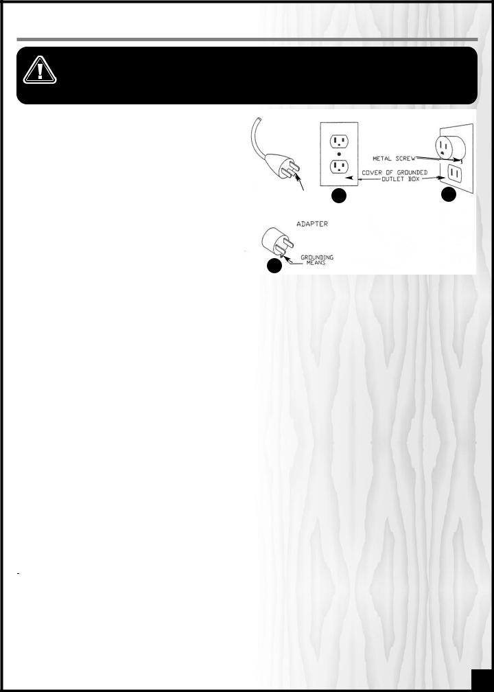
GROUNDING INSTRUCTIONS |
|
|
|
|
|
|
|
|
|
|
|
|
|
|
|
|
|
|
|
|
|
|
|
|
|
|
|
|
|
|
|
|
|
Grounding methods |
|
|
|
|
|
|
|||||||||
In the event of an electrical malfunction or short circuit, |
|
|
|
|
|
|
|
|
|
|
|
|
|
|
|
|
|
|
|
|
|
|
|
|
grounding reduces the risk of electric shock. The motor |
|
|
|
|
|
|
|
|
|
|
|
|
|
|
|
|
|
|
|
|
|
|
|
|
of this machine is wired for 120V single phase opera- |
|
|
|
|
|
|
|
|
|
|
|
|
|
|
|
|
|
|
|
|
|
|
|
|
tion and is equipped with a 3-conductor cord and a 3- |
|
|
|
|
|
|
|
|
|
|
|
|
|
|
|
|
|
Metal screw |
|
|
|
|
|
|
prong grounded plug to fit a grounded type recepta- |
|
|
|
|
|
|
|
|
|
|
|
|
|
|
|
|
|
|
|
|
|
|
|
|
|
|
|
|
|
|
|
|
|
|
|
|
|
|
|
|
|
|
|
|
|
|
|
|
|
cle, A. |
|
|
|
|
|
|
|
|
|
|
|
|
|
|
|
|
|
Cover of Ground |
|
|
|
|
|
|
Do not remove the 3rd prong (grounding pin) to make |
|
|
|
|
|
|
|
|
|
|
|
|
|
|
|
|
|
|
|
|
|
|
||
|
|
Grounding |
|
|
|
|
|
|
|
|
|
|
|
|
outlet box |
|
|
|
|
|
||||
it fit into an old 2-hole wall socket. If an adaptor plug is |
|
|
|
|
|
|
|
A |
|
|
|
|
|
|
|
|
|
B |
|
|||||
|
|
|
|
|
|
|
|
|
|
|
|
|
|
|
|
|
||||||||
|
|
Pin |
|
|
|
|
|
|
|
|
|
|
|
|
|
|
|
|||||||
used, B, it must be attached to the metal screw of the |
|
|
|
|
|
|
|
|
|
|
|
|
|
|
|
|
|
|
|
|
|
|||
|
|
|
|
|
|
|
|
|
|
|
|
|
|
|
|
|
|
|
|
|
|
|
|
|
receptacle. |
|
|
|
|
|
|
|
|
|
|
|
|
|
|
|
|
|
|
|
|
|
|
|
|
|
|
|
|
|
|
|
|
|
|
|
|
|
|
|
|
|
|
|
|
|
|
|
|
|
Note: The use of an adaptor plug is illegal in some areas, |
|
|
|
|
|
|
|
|
Adapter |
|
|
|
|
|
|
|
|
|
|
|
||||
including Canada. Check your local codes. |
|
|
|
|
|
|
|
|
|
|
|
|
|
|
|
|
|
|
|
|
|
|
|
|
|
|
|
|
|
|
|
|
|
|
|
|
|
|
|
|
|
|
|
|
|
|
|
|
|
Grounded, cord-connected tools intended for use on a |
|
|
|
|
|
|
|
|
|
|
|
|
|
|
|
|
|
|
|
|
|
|
|
|
supply circuit having a nominal rating less than 150 |
|
|
|
|
|
|
|
|
|
|
|
|
|
|
|
|
|
|
|
|
|
|
|
|
|
|
|
|
|
|
|
|
|
Grounding |
|
|
|
|
|
|
|
|
|
|
|
|
|
||
volts: This tool is intended fo use on a circuit that has an |
|
|
|
C |
|
|
|
|
|
|
|
|
|
|
|
|
|
|
|
|
|
|
||
outlet that looks like the one illustrated in A. The tool has |
|
|
|
|
|
|
|
|
mean |
|
|
|
|
|
|
|
|
|
|
|
|
|||
|
|
|
|
|
|
|
|
|
|
|
|
|
|
|
|
|
|
|
|
|
|
|
|
|
a grounding plug that looks like the plug illustrated in |
|
|
|
|
|
|
|
|
|
|
|
|
|
|
|
|
|
|
|
|
|
|
|
|
|
|
|
|
|
|
|
|
|
|
|
|
|
|
|
|
|
|
|
|
|
|
|
|
|
A. A temporary adapter, which looks like the addapter illustrated in B and C, may be used to connect this plug to a 2 pole receptacle as shown in B if a properly grounded outlet is not available. The temporary adapter should be used only until a properly grounded outlet can be insalled by a qualified electrician. This adapter is not permitted in Canada. The green-colored rigid ear, lug and the like, extending from the adapter, must be connected to a permanent ground such as a properly grounded outlet box.
This tool is equipped with an electric cord having an equipment-grounding conductor and a grounding plug. The plug must be plugged into a matching outlet that is properly installed and grounded in accordance with all local codes and ordinances.
Improper connection of the equipment-grounding conductor can result in a risk of electric shock. The conductor with insulation having an outer surface that is green with or without yellow stripes is the equipment-grounding conductor. If repair or replacement of the electric cord or plug is necessary, do not connect the equipment-grounding conductor to a live terminal.uter surface that is green with or without yellow stripes is the equipment-grounding conductor. If repair or replacement of the electric cord or plug is necessary, do not connect the equipment-grounding conductor to a live terminal.
DO NOT MODIFY THE PLUG PROVIDED.
If it will not fit your receptacle, have the proper receptacle installed by a qualified electrician.
CHECK with a qualified electrician or service person if you do not completely understand these grounding instructions, or if you are not sure the tool is properly grounded.
EXTENSION CORDS
USE ONLY 3-WIRE EXTENSION CORDS THAT HAVE 3-PRONG GROUNDING PLUGS AND 3-POLE RECEPTACLES THAT ACCEPT THE TOOLS’ PLUG. REPAIR OR REPLACE A DAMAGED OR WORN POWER CORD OR PLUG IMMEDIATELY
If you find it necessary to use an extension cord with your machine make sure the cord rating is suitable for the amperage listed on the motor I.D. plate. An undersized cord will cause a drop in line voltage resulting in loss of power and overheating. The accompanying chart shows the correct size extension cord to be used based on cord length and motor I.D. plate amp rating. If in doubt, use the next heavier gauge. The smaller the number the heavier the gauge.
AMPERES |
|
EXTEN SI ON CORD LE NGTH |
|
||||
(AMPS) |
25 Feet |
50 Feet |
75 Feet |
100 Feet |
150 Feet |
200 Feet |
|
< 5 |
16 |
16 |
16 |
14 |
12 |
12 |
|
5 |
à 8 |
16 |
16 |
14 |
12 |
10 |
NR |
8 à 12 |
14 |
14 |
12 |
10 |
NR |
NR |
|
12 |
à 15 |
12 |
12 |
10 |
10 |
NR |
NR |
15 |
à 20 |
10 |
10 |
10 |
NR |
NR |
NR |
21 |
à 30 |
10 |
NR |
NR |
NR |
NR |
NR |
*Based on limiting the line voltage drop to 5V at 150% of the rated amperes. NR = Not Recommended
7

SCROLL SAW
EX-16, EX-21 or EX-30
IDENTIFICATION OF MAIN PARTS AND COMPONENTS
(EX-21- shown) |
|
|
|
|
A |
|
B |
|
|
|
C |
|
|
|
D |
|
|
|
E |
|
|
|
F |
|
O |
|
N |
|
|
|
|
|
|
|
G |
|
|
|
H |
OPPOSITE SIDE VIEW |
|
I |
|
|
P |
|
|
|
|
J |
|
|
|
|
|
|
|
|
K |
|
|
|
L |
|
|
|
M |
|
Q |
|
|
A- |
UPPER ARM ADJUSTER |
J- |
TILT HANDLE |
B- |
VARIABLE BLADE SPEED CONTROL KNOB |
K- |
ANGLE INDICATOR |
C- |
ON/OFF SWITCH (WITH SAFETY DEVICE) |
L- |
ANGLE ADJUSTMENT SCALE |
D- |
BLADE TENSION LEVER |
M- |
MOUNTING HOLES (4) |
E- |
BLADE GUARD |
N- |
BLOWER |
F- |
BLADE |
O- |
UPPER ARM |
G- |
WORKPIECE HOLD DOWN |
P- |
MOTOR |
H- |
TABLE |
Q- |
BLADE HOLDER SOCKETS |
I- BLADE TILT LOCKING LEVER |
|
(EX-21 & EX-30 ONLY) |
|
|
|
||
8
 Loading...