


HIGH STATIC PRESSURE
DUCT TYPE AIR CONDITIONER
T E C H N I C A L M A N U A L
AR90
CONTENTS
1. FEATURES ........................................................................ |
2 |
2. DIMENSIONS .................................................................... |
4 |
3. WIRING DIAGRAM............................................................ |
6 |
4. PERFORMANCE DATA ..................................................... |
9 |
5. OPERATION DETAILS .................................................... |
11 |
6. INSTALLATION INSTRUCTIONS .................................... |
12 |
7. SPECIFICATIONS ........................................................... |
13 |
– 1 –
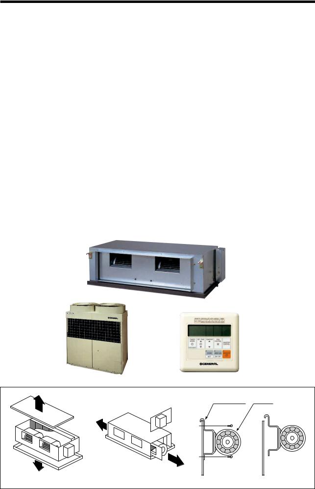
1. FEATURES
●High static pressure
•Recommended external static pressure is 200Pa (Max. 300Pa).
●Functional LCD wired remote controller (See the next page for details.)
•Weekly timer
Air conditioner ON/OFF can be set for one whole week, including 2 times a day.
•Auto restart function in case of power failure
•Zone control
Only preset air conditioners can be stopped by pressing the ZONE CONTROL button.
●Energy saving operation
•ENERGY SAVE mode uses a computer program to economically control unit operation by raising the set temperature slightly in the cooling mode and lowering the set temperature in the heating mode.
●Pipe length up to 50m with height differential up to 30m
●Easy maintenance
•Fan motor maintenance
Fan motor maintenance can be performed from top, bottom, right side, or left side. (Fig. 1) Fan motor hooks to the panel and is safe and easy to mount and dismount. (Fig. 2)
●Remote sensor unit (Option)
•Temperature sensor unit to be placed in the room
TOP ACCESS |
SIDE ACCESS |
PILOT PLATE |
MOTOR |
|
|||
|
(BOTH SIDES) |
|
|
BOTTOM ACCESS |
Fig. 1 |
|
Fig. 2 |
|
|
|
|
|
|
– 2 – |
|
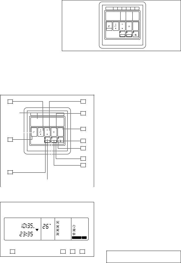
REMOTE CONTROLLER
WIRE REMOTE CONTROLLER WITH WEEKLY TIMER
REMOTE CONTROLLER WITH WEEKLY TIMER
DAY CODE |
1 |
2 |
3 |
4 |
5 |
6 |
|
MON |
TUE |
WED |
THU |
FRI |
SAT |
||
|
|||||||
TIMER SET TIME |
TEMP./DAY |
FAN |
|
|
|||
MODE |
|
|
|
CONTROL |
MASTER |
||
|
|
|
|
|
|||
|
|
|
|
|
CONTROL |
||
CLOCK ADJUST |
|
|
|
|
|
|
|
|
|
|
ZONE |
ENERGY SAVE |
START/STOP |
||
|
|
|
|
|
|||
|
|
|
SET |
DAY OFF |
|
|
|
FEATURES
Three kinds of timer setup (OFF/ON/WEEKLY) are possible.
Function of weekly timer
•Setting of different on-off time by day
•Setting of set on-off time twice a day
•Setting of time in 5 minute steps
•Timer operation of a reserved day can be temporarily cancelled by pushing the “DAY OFF” button.
•Time setting can be left until the next day.
1START/STOP Button
Pressed to start and stop operation.
11 |
|
|
|
|
|
|
|
|
|
|
|
|
|
|
|
|
12 |
|
2 |
OPERATION Lamp |
|
|
|
|
|
|
|
|
|
|
|
|
|
|
|
|
|
|
|
|
|
|
Lights during operation and when the timer is on. |
|
|
|
REMOTE CONTROLLER WITH WEEKLY TIMER |
|
|
3 |
DAY OFF Button |
||||||||||||||
|
Display |
DAY CODE |
1 |
|
2 |
|
|
3 |
4 |
|
5 |
6 |
13 |
|
|
Temporary cancellation of one day timer |
|||||
|
|
|
|
|
|
MON |
|
TUE |
|
|
WED |
THU |
|
FRI |
SAT |
|
|
|
|||
|
|
|
|
|
|
|
|
|
|
|
|
|
|
|
|
|
|
|
|
4 |
ENERGY SAVE Button |
|
|
|
|
|
|
|
|
|
|
|
|
|
|
|
|
|
|
|
|
||
|
|
|
|
|
|
|
|
|
|
|
|
|
|
|
|
|
|
|
|
|
Turns energy save mode on and off. |
|
|
|
|
|
|
|
|
|
|
|
|
|
|
|
|
|
14 |
|
5 |
ENERGY SAVE Button |
|
|
|
|
|
TIMER |
SET TIME |
TEMP./DAY |
FAN |
|
|
|
|
||||||||||
|
|
|
|
MODE |
|
|
|
|
|
|
|
CONTROL |
|
MASTER |
|
||||||
|
10 |
|
|
|
|
|
|
|
|
|
|
|
|
|
|
CONTROL |
|
|
|
Lights when the unit is in the energy save mode. |
|
|
|
|
|
|
|
|
|
|
|
|
|
|
|
|
|
|
|
||||
|
|
|
|
|
|
|
|
|
|
|
|
|
|
|
|
|
|
|
|
||
9 |
|
|
CLOCK ADJUST |
|
|
|
|
ZONE |
|
|
|
START/STOP |
1 |
|
6 |
SET Button |
|||||
|
|
|
|
|
|
|
|
|
|
|
|||||||||||
|
|
|
|
|
|
|
|
ENERGY SAVE |
|
|
|||||||||||
|
|
|
|
|
|
|
|
|
|
|
|
|
|
|
|
Sets the date, hour, minute and on-off time. |
|||||
|
|
|
|
|
|
|
|
SET |
DAY OFF |
|
|
|
|
|
|||||||
|
|
|
|
|
|
|
|
|
|
|
|
|
|
|
|
|
|
|
|
||
|
|
|
|
|
|
|
|
|
|
|
|
|
|
|
|
|
|
2 |
|
7 |
ZONE Button |
|
|
|
|
|
|
|
|
|
|
|
|
|
|
|
|
|
|
|
|
Use to turn zone control on and off. |
|
|
|
|
|
|
|
|
|
|
|
|
|
|
|
|
|
|
|
|
|
|
|
|
|
|
|
|
|
|
|
|
|
|
|
|
|
|
|
|
|
3 |
|
8 |
ZONE Lamp |
|
|
|
|
|
|
|
|
|
|
|
|
|
|
|
|
|
|
|
|
Lights when the unit is in the zone control mode. |
|
|
|
|
|
|
|
|
|
|
|
|
|
|
|
|
|
|
|
|
|
|
|
|
|
|
|
|
|
|
|
|
|
|
|
|
|
|
|
|
|
4 |
|
9 |
CLOCK ADJUST Button |
|
|
|
|
|
|
|
|
|
|
|
|
|
|
|
|
|
|
|
|
10 TIMER MODE Button |
|
8 |
|
|
|
|
|
|
|
|
|
|
|
|
|
|
|
|
5 |
|
|
Changes the timer mode (NON STOP, OFF TIMER, |
|
|
|
|
|
|
|
|
|
|
|
|
|
|
|
|
|
|
|
|
|
|
|
|
|
|
|
|
|
|
|
|
|
|
|
|
|
|
|
|
|
|
|
|
ON TIMER, WEEKLY TIMER). |
|
7 |
|
|
|
|
|
|
|
|
|
|
|
|
|
|
|
|
6 |
|
11 |
SET TIME Button |
|
|
|
|
|
|
|
|
|
|
|
|
|
|
|
|
|
|
||||
|
|
|
|
|
|
|
|
|
|
|
|
|
|
|
|
|
|
|
|
||
|
|
|
|
|
|
|
|
|
|
|
|
|
|
|
|
|
|
|
|
|
Sets the current time and on-off time. |
|
|
|
|
|
|
|
|
|
|
|
|
|
|
|
|
|
|
|
|
|
|
|
|
|
|
|
|
|
|
|
|
|
|
|
|
|
|
|
|
|
|
12 |
TEMP./DAY Button |
|
|
|
|
|
|
|
|
|
|
|
|
|
|
|
|
|
|
|
|
|
Sets the indoor temperature / day. |
Display panel
|
|
15 |
|
|
|
|
|
16 |
|
|
|
|
|
17 |
|
|
|||
|
|
|
|
|
|
|
|
|
|
|
|
|
|
|
|
|
|
|
|
NON STOP |
CLOCK |
TEMP. |
|
AUTO |
|
|
|
|
|
|
||||||||
OFFON |
OFF |
C |
HIGH |
|
|
HEAT |
||||||||||||
ON |
|
|
|
|
||||||||||||||
TIMER |
TIMER |
DAY |
MED |
|
|
FAN |
||||||||||||
WEEKLY |
OFF |
|
|
LOW |
|
|
COOL |
|||||||||||
DAY OFF |
|
|||||||||||||||||
|
|
|
|
|
|
|
ON |
|
|
|
|
|
|
|
|
|
|
|
|
1 |
|
|
2 |
|
NEXT DAY |
|
|
|
|
|
|
|
|
DEFROST |
|
TEST |
|
|
|
|
|
|
|
|||||||||||||
|
|
|
|
|
|
|
|
|
|
|
|
|||||||
|
|
|
|
|
|
|
|
|
||||||||||
|
|
|
|
|
|
|
|
|
|
|
|
|
|
|||||
|
|
|
|
|
|
|
|
|
|
|
|
|
|
|
|
|
|
|
|
|
|
|
|
|
|
|
|
|
|
|
|
|
|
|
|||
18 |
|
|
|
|
19 |
|
20 |
21 |
||||||||||
#13 FAN CONTROL Button
14MASTER CONTROL Button
Selects the operating mode
(HEAT, FAN, COOL).
15Clock Display
16Set Temperature / Day Display (TEMP./DAY)
17Operation Mode Display
18Timer Mode Display
#19 Fan Speed Display
20DEFROST Display
21TEST Display
#NOTE :
This model does not have a fan speed function.
– 3 –
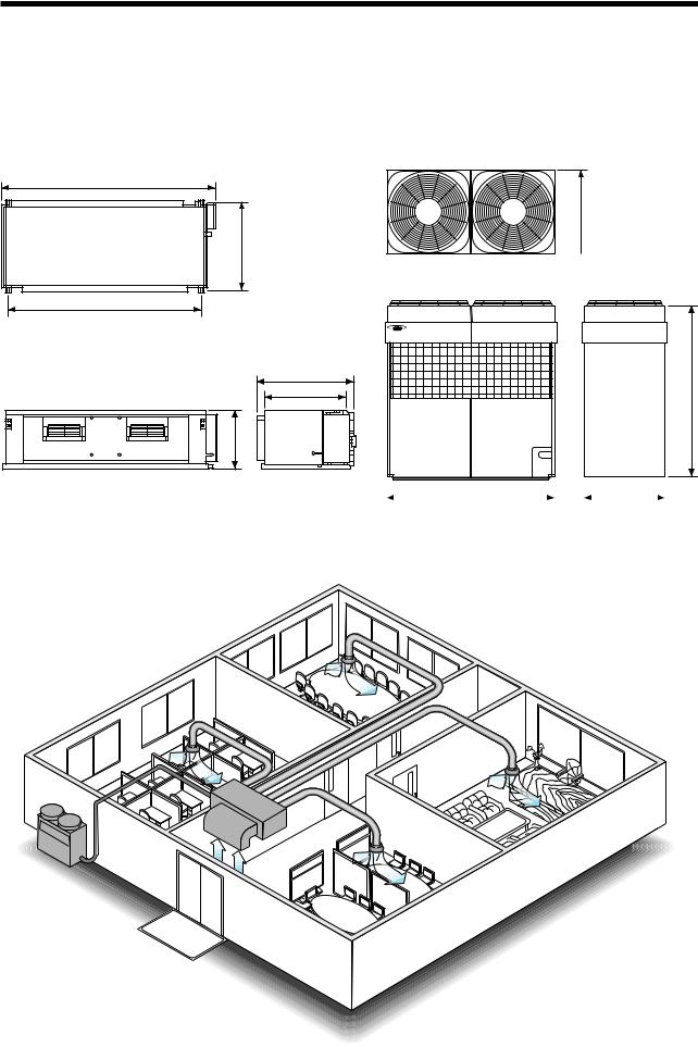
2. DIMENSIONS
■ INDOOR UNIT |
■ OUTDOOR UNIT |
(Unit : mm)
1,550
660 650
650
1,410
700 |
1,380 |
|
600 |
||
|
450
1,300 |
|
650 |
|
|
|
● SAMPLE INSTALLATION
– 4 –
 Loading...