


 Loading...
GE Healthcare
CARESCAPE™ V100 Vital Signs Monitor
Service Manual
CARESCAPE V100 Vital Signs Monitor
English
2037106-001 B (paper)
© 2007, 2008 General Electric Company.
All Rights Reserved.

GE Healthcare
CARESCAPE™ V100 Vital Signs Monitor
Service Manual
CARESCAPE V100 Vital Signs Monitor
English
2037106-001 B (paper)
© 2007, 2008 General Electric Company.
All Rights Reserved.

NOTE: The information in this manual also applies to CARESCAPE V100 Vital Signs Monitor software version RAA. There are no user-apparent differences among these software versions. Due to continuing product innovation, specifications in this manual are subject to change without notice.
NOTE: For technical documentation purposes, the abbreviation GE is used for the legal entity name, GE Medical Systems Information Technologies.
Listed below are GE Medical Systems Information Technologies trademarks. All other trademarks contained herein are the property of their respective owners.
Ohmeda Oximetry and other trademarks (OxyTip+, PIr, TruSat, TruSignal, TruTrak+) are the property of GE Medical Systems Information Technologies, a division of General Electric Corporation. All other product and company names are the property of their respective owners.
Alaris Turbo Temp and IVAC are trademarks of Cardinal Health, Inc.
CRITIKON, DINAMAP, SuperSTAT, and DURA-CUF and SOFT-CUF Blood Pressure Cuffs are trademarks of GE Medical Systems Information Technologies.
Masimo SET, LNOP, and LNCS are trademarks of Masimo Corporation. Possession or purchase of this device does not convey any express or implied license to use the device with replacement parts which would, alone, or in combination with this device, fall within the scope of one or more of the patents relating to the device.
Nellcor, OxiMax, C-LOCK and SatSeconds are trademarks of Nellcor Puritan Bennett.
T-2 |
CARESCAPE V100 Vital Signs Monitor |
2037106-001 B |
|
|
17 September 2008 |

Contents
1 Introduction . . . . . . . . . . . . . . . . . . . . . . 1-1
Revision History . . . . . . . . . . . . . . . . . . . . . . . . . . . . . . . . . . . . . . . . . . . . . . . . . 1-3
Manual Purpose . . . . . . . . . . . . . . . . . . . . . . . . . . . . . . . . . . . . . . . . . . . . . . . . . 1-3
Ordering Manuals . . . . . . . . . . . . . . . . . . . . . . . . . . . . . . . . . . . . . . . . . . . . . . . 1-3
Safety Information . . . . . . . . . . . . . . . . . . . . . . . . . . . . . . . . . . . . . . . . . . . . . . 1-3
Responsibility of the Manufacturer . . . . . . . . . . . . . . . . . . . . . . . . . . . . . . . . . .1-4 General . . . . . . . . . . . . . . . . . . . . . . . . . . . . . . . . . . . . . . . . . . . . . . . . . . . . . . . . . . . .1-4 References to Persons, Places, and Institutions . . . . . . . . . . . . . . . . . . . . . .1-4 Warnings, Cautions, and Notes . . . . . . . . . . . . . . . . . . . . . . . . . . . . . . . . . . . . .1-5 Product Specific Hazards . . . . . . . . . . . . . . . . . . . . . . . . . . . . . . . . . . . . . . . . . . .1-5
Equipment Symbols . . . . . . . . . . . . . . . . . . . . . . . . . . . . . . . . . . . . . . . . . . . . . 1-7
Service Requirements . . . . . . . . . . . . . . . . . . . . . . . . . . . . . . . . . . . . . . . . . . . 1-9
Equipment ID . . . . . . . . . . . . . . . . . . . . . . . . . . . . . . . . . . . . . . . . . . . . . . . . . . . 1-9
Intended Audience . . . . . . . . . . . . . . . . . . . . . . . . . . . . . . . . . . . . . . . . . . . . . . 1-9
Intended Use . . . . . . . . . . . . . . . . . . . . . . . . . . . . . . . . . . . . . . . . . . . . . . . . . . . . 1-10
General Use . . . . . . . . . . . . . . . . . . . . . . . . . . . . . . . . . . . . . . . . . . . . . . . . . 1-10
Related Manuals . . . . . . . . . . . . . . . . . . . . . . . . . . . . . . . . . . . . . . . . . . . . . . . . . 1-10
Service Policy . . . . . . . . . . . . . . . . . . . . . . . . . . . . . . . . . . . . . . . . . . . . . . . . . . 1-10
Service Contracts . . . . . . . . . . . . . . . . . . . . . . . . . . . . . . . . . . . . . . . . . . . . . . . . 1-10
Assistance . . . . . . . . . . . . . . . . . . . . . . . . . . . . . . . . . . . . . . . . . . . . . . . . . . . . . . . 1-10
Service . . . . . . . . . . . . . . . . . . . . . . . . . . . . . . . . . . . . . . . . . . . . . . . . . . . . . . . . . . 1-11
Packing Instructions . . . . . . . . . . . . . . . . . . . . . . . . . . . . . . . . . . . . . . . . . 1-11
Insurance . . . . . . . . . . . . . . . . . . . . . . . . . . . . . . . . . . . . . . . . . . . . . . . . . . . 1-11
Service No Charge Rental . . . . . . . . . . . . . . . . . . . . . . . . . . . . . . . . . . . . . . . . . 1-12
Repair Parts . . . . . . . . . . . . . . . . . . . . . . . . . . . . . . . . . . . . . . . . . . . . . . . . . . . . . 1-12
Disposal of Product Waste . . . . . . . . . . . . . . . . . . . . . . . . . . . . . . . . . . . . . . 1-12
Batteries . . . . . . . . . . . . . . . . . . . . . . . . . . . . . . . . . . . . . . . . . . . . . . . . . . . . . . . . . 1-12
Patient Applied Parts . . . . . . . . . . . . . . . . . . . . . . . . . . . . . . . . . . . . . . . . . . . . . 1-13
Packaging Material . . . . . . . . . . . . . . . . . . . . . . . . . . . . . . . . . . . . . . . . . . . . . . . 1-13
Monitor . . . . . . . . . . . . . . . . . . . . . . . . . . . . . . . . . . . . . . . . . . . . . . . . . . . . . . . . . . 1-13
2037106-001B |
CARESCAPE V100 Vital Signs Monitor |
i |

2 Equipment Overview . . . . . . . . . . . . . . 2-1
Equipment Description . . . . . . . . . . . . . . . . . . . . . . . . . . . . . . . . . . . . . . . . . . . 2-3
Product Configurations . . . . . . . . . . . . . . . . . . . . . . . . . . . . . . . . . . . . . . . . . . . . .2-3
Basic Components . . . . . . . . . . . . . . . . . . . . . . . . . . . . . . . . . . . . . . . . . . . . . . . 2-4
Buttons . . . . . . . . . . . . . . . . . . . . . . . . . . . . . . . . . . . . . . . . . . . . . . . . . . . . . . . . . . . .2-4
Front Panel . . . . . . . . . . . . . . . . . . . . . . . . . . . . . . . . . . . . . . . . . . . . . . . . . . . . . . 2-5
Product Compliance . . . . . . . . . . . . . . . . . . . . . . . . . . . . . . . . . . . . . . . . . . . . . . 2-7
Theory of Operation . . . . . . . . . . . . . . . . . . . . . . . . . . . . . . . . . . . . . . . . . . . . . . 2-8
Introduction . . . . . . . . . . . . . . . . . . . . . . . . . . . . . . . . . . . . . . . . . . . . . . . . . . . . . . .2-8
Overall Principles of Operation . . . . . . . . . . . . . . . . . . . . . . . . . . . . . . . . . . . . 2-8
SpO2 . . . . . . . . . . . . . . . . . . . . . . . . . . . . . . . . . . . . . . . . . . . . . . . . . . . . . . . . . . . . . .2-9
Cuff Blood Pressure (NIBP) and Pulse . . . . . . . . . . . . . . . . . . . . . . . . . . . . . . . .2-9
DINAMAP SuperSTAT Algorithm . . . . . . . . . . . . . . . . . . . . . . . . . . . . . . . . . . 2-10
Systolic Search . . . . . . . . . . . . . . . . . . . . . . . . . . . . . . . . . . . . . . . . . . . . . . . . . . . 2-11
DINAMAP Classic and Auscultatory Reference Algorithm . . . . . . . . . . . 2-12
Systolic Search . . . . . . . . . . . . . . . . . . . . . . . . . . . . . . . . . . . . . . . . . . . . . . . . . . . 2-13 Reference Used to Determine NIBP Accuracy . . . . . . . . . . . . . . . . . . . . . . 2-13
CARESCAPE V100 Monitors With Intra-Arterial Reference
(DINAMAP SuperSTAT and Classic Technology) . . . . . . . . . . . . . . . . 2-14 CARESCAPE V100 Monitors With Auscultatory Reference
(DINAMAP Auscultatory Reference Technology) . . . . . . . . . . . . . . . . 2-14 Temperature . . . . . . . . . . . . . . . . . . . . . . . . . . . . . . . . . . . . . . . . . . . . . . . . . . . . . 2-14 Host Communication Port . . . . . . . . . . . . . . . . . . . . . . . . . . . . . . . . . . . . . . . . 2-14
Functional Description . . . . . . . . . . . . . . . . . . . . . . . . . . . . . . . . . . . . . . . . . . 2-14
Main Board PWA . . . . . . . . . . . . . . . . . . . . . . . . . . . . . . . . . . . . . . . . . . . . . . . . . 2-15
User Interface (UI) Board PWA . . . . . . . . . . . . . . . . . . . . . . . . . . . . . . . . . . . . 2-15
SpO2 PWA . . . . . . . . . . . . . . . . . . . . . . . . . . . . . . . . . . . . . . . . . . . . . . . . . . . . . . . 2-16
Printer . . . . . . . . . . . . . . . . . . . . . . . . . . . . . . . . . . . . . . . . . . . . . . . . . . . . . . . . . . . 2-16
Pneumatics . . . . . . . . . . . . . . . . . . . . . . . . . . . . . . . . . . . . . . . . . . . . . . . . . . . . . . 2-16
Optical Switch . . . . . . . . . . . . . . . . . . . . . . . . . . . . . . . . . . . . . . . . . . . . . . . . . . . 2-16
ii |
CARESCAPE V100 Vital Signs Monitor |
2037106-001B |

3
4
Installation . . . . . . . . . . . . . . . . . . . . . . . 3-1
Connections . . . . . . . . . . . . . . . . . . . . . . . . . . . . . . . . . . . . . . . . . . . . . . . . . . . . 3-3
Right-Side Panel . . . . . . . . . . . . . . . . . . . . . . . . . . . . . . . . . . . . . . . . . . . . . . . . . . .3-3
Rear Panel . . . . . . . . . . . . . . . . . . . . . . . . . . . . . . . . . . . . . . . . . . . . . . . . . . . . . . . . .3-3
Powering the Monitor . . . . . . . . . . . . . . . . . . . . . . . . . . . . . . . . . . . . . . . . . . . . . .3-4
Power Sources . . . . . . . . . . . . . . . . . . . . . . . . . . . . . . . . . . . . . . . . . . . . . . . . .3-4
Battery Charging . . . . . . . . . . . . . . . . . . . . . . . . . . . . . . . . . . . . . . . . . . . . . . .3-4
BATTERY OK . . . . . . . . . . . . . . . . . . . . . . . . . . . . . . . . . . . . . . . . . . . . . . . . . . .3-5
Battery Alarms . . . . . . . . . . . . . . . . . . . . . . . . . . . . . . . . . . . . . . . . . . . . . . . . .3-5
E13 Battery Low . . . . . . . . . . . . . . . . . . . . . . . . . . . . . . . . . . . . . . . . . . . . . . .3-6
Unpacking and Preparation for Installation . . . . . . . . . . . . . . . . . . . . . . . . 3-6
Configuring Your V100 Monitor . . . . . . . . . . . . . . . . . . . . . . . . . . . . . . . . . . . 3-7
Operating Modes . . . . . . . . . . . . . . . . . . . . . . . . . . . . . . . . . . . . . . . . . . . . . . . . . . .3-7
Clinical Mode . . . . . . . . . . . . . . . . . . . . . . . . . . . . . . . . . . . . . . . . . . . . . . . . . .3-7
Configuration Mode . . . . . . . . . . . . . . . . . . . . . . . . . . . . . . . . . . . . . . . . . . . .3-7
Advanced Configuration Mode . . . . . . . . . . . . . . . . . . . . . . . . . . . . . . . 3-11
Service Mode . . . . . . . . . . . . . . . . . . . . . . . . . . . . . . . . . . . . . . . . . . . . . . . . 3-12
Host Communications Connector . . . . . . . . . . . . . . . . . . . . . . . . . . . . . . . . 3-15
DB15 Connector Pin Assignments . . . . . . . . . . . . . . . . . . . . . . . . . . . . . . . . . 3-15
Connection Details . . . . . . . . . . . . . . . . . . . . . . . . . . . . . . . . . . . . . . . . . . . 3-15
Maintenance . . . . . . . . . . . . . . . . . . . . . 4-1
Preventative Maintenance . . . . . . . . . . . . . . . . . . . . . . . . . . . . . . . . . . . . . . . 4-3
General . . . . . . . . . . . . . . . . . . . . . . . . . . . . . . . . . . . . . . . . . . . . . . . . . . . . . . . . . . . .4-3
Integrity of Hoses and Cuffs . . . . . . . . . . . . . . . . . . . . . . . . . . . . . . . . . . . .4-3
Visual Inspection . . . . . . . . . . . . . . . . . . . . . . . . . . . . . . . . . . . . . . . . . . . . . . . . 4-3
Cleaning . . . . . . . . . . . . . . . . . . . . . . . . . . . . . . . . . . . . . . . . . . . . . . . . . . . . . . . 4-4
Cleaning the Monitor . . . . . . . . . . . . . . . . . . . . . . . . . . . . . . . . . . . . . . . . . . .4-4
Cuffs . . . . . . . . . . . . . . . . . . . . . . . . . . . . . . . . . . . . . . . . . . . . . . . . . . . . . . . . . .4-5
Temperature Devices . . . . . . . . . . . . . . . . . . . . . . . . . . . . . . . . . . . . . . . . . .4-6
SpO2 Sensors . . . . . . . . . . . . . . . . . . . . . . . . . . . . . . . . . . . . . . . . . . . . . . . . . .4-6
Long-Term Storage . . . . . . . . . . . . . . . . . . . . . . . . . . . . . . . . . . . . . . . . . . . . . . 4-6
Battery Care . . . . . . . . . . . . . . . . . . . . . . . . . . . . . . . . . . . . . . . . . . . . . . . . . . . . . . .4-7
Replacing the Battery . . . . . . . . . . . . . . . . . . . . . . . . . . . . . . . . . . . . . . . . . .4-8
2037106-001B |
CARESCAPE V100 Vital Signs Monitor |
iii |

5
6
Fuses . . . . . . . . . . . . . . . . . . . . . . . . . . . . . . . . . . . . . . . . . . . . . . . . . . . . . . . . . . . . . .4-9
Parameter Level Functional Testing . . . . . . . . . . . . . . . . . . . . . . . . . . . . . . . . 4-9
NIBP . . . . . . . . . . . . . . . . . . . . . . . . . . . . . . . . . . . . . . . . . . . . . . . . . . . . . . . . . . . . . . .4-9 Temperature . . . . . . . . . . . . . . . . . . . . . . . . . . . . . . . . . . . . . . . . . . . . . . . . . . . . . . .4-9 Ohmeda, Nellcor, and Masimo SpO2 Technologies . . . . . . . . . . . . . . . . . 4-10 Calibration Procedures and Tests . . . . . . . . . . . . . . . . . . . . . . . . . . . . . . . . . 4-10 Annual Procedures . . . . . . . . . . . . . . . . . . . . . . . . . . . . . . . . . . . . . . . . . . . . . . . 4-10
Parameter Test Procedures . . . . . . . . . . . . . . . . . . . . . . . . . . . . . . . . . . . 4-11 Pneumatic Leakage Testing . . . . . . . . . . . . . . . . . . . . . . . . . . . . . . . . . . 4-12 Pressure Transducer Verification . . . . . . . . . . . . . . . . . . . . . . . . . . . . . 4-12 Pressure Transducer Calibration . . . . . . . . . . . . . . . . . . . . . . . . . . . . . . 4-13 Overpressure Verification . . . . . . . . . . . . . . . . . . . . . . . . . . . . . . . . . . . . 4-13 Button Testing . . . . . . . . . . . . . . . . . . . . . . . . . . . . . . . . . . . . . . . . . . . . . . . 4-14 LED Tests . . . . . . . . . . . . . . . . . . . . . . . . . . . . . . . . . . . . . . . . . . . . . . . . . . . . 4-14 External DC Verification . . . . . . . . . . . . . . . . . . . . . . . . . . . . . . . . . . . . . . 4-14 NIBP Determination . . . . . . . . . . . . . . . . . . . . . . . . . . . . . . . . . . . . . . . . . . 4-14 NIBP Overpressure Verification . . . . . . . . . . . . . . . . . . . . . . . . . . . . . . . 4-15 Temperature (Perform if equipped with Temp module) . . . . . . . . . 4-15 SpO2 (Perform only if equipped with SpO2 module) . . . . . . . . . . . . 4-16 Printer Output Test . . . . . . . . . . . . . . . . . . . . . . . . . . . . . . . . . . . . . . . . . . . 4-16 Safety Testing . . . . . . . . . . . . . . . . . . . . . . . . . . . . . . . . . . . . . . . . . . . . . . . 4-17 SpO2 Circuit Leakage Test . . . . . . . . . . . . . . . . . . . . . . . . . . . . . . . . . . . . 4-17 Temp Circuit Leakage Test . . . . . . . . . . . . . . . . . . . . . . . . . . . . . . . . . . . 4-17
Test Results Form . . . . . . . . . . . . . . . . . . . . . . . . . . . . . . . . . . . . . . . . . . . . . . 4-18
Troubleshooting . . . . . . . . . . . . . . . . . . 5-1
Alarm Code Interpretation . . . . . . . . . . . . . . . . . . . . . . . . . . . . . . . . . . . . . . . . 5-3
System Failures . . . . . . . . . . . . . . . . . . . . . . . . . . . . . . . . . . . . . . . . . . . . . . . . . . . .5-3
Alarm Conditions and Error Codes . . . . . . . . . . . . . . . . . . . . . . . . . . . . . .5-3
Error Log . . . . . . . . . . . . . . . . . . . . . . . . . . . . . . . . . . . . . . . . . . . . . . . . . . . . . . . . . .5-3
Procedure to View and Print Error Code History Log: . . . . . . . . . . . . .5-3
Error Codes . . . . . . . . . . . . . . . . . . . . . . . . . . . . . . . . . . . . . . . . . . . . . . . . . . . .5-5
Parts List, Drawings, and
Replacement . . . . . . . . . . . . . . . . . . . . . 6-1
Ordering Parts . . . . . . . . . . . . . . . . . . . . . . . . . . . . . . . . . . . . . . . . . . . . . . . . . . . 6-3
iv |
CARESCAPE V100 Vital Signs Monitor |
2037106-001B |

Service Parts . . . . . . . . . . . . . . . . . . . . . . . . . . . . . . . . . . . . . . . . . . . . . . . . . . . . 6-3
Compatible Parts . . . . . . . . . . . . . . . . . . . . . . . . . . . . . . . . . . . . . . . . . . . . . . . . . . .6-3
Field-Replaceable Units (FRUs) . . . . . . . . . . . . . . . . . . . . . . . . . . . . . . . . . . . . . .6-8
FRU List . . . . . . . . . . . . . . . . . . . . . . . . . . . . . . . . . . . . . . . . . . . . . . . . . . . . . . .6-8
FRU Photos . . . . . . . . . . . . . . . . . . . . . . . . . . . . . . . . . . . . . . . . . . . . . . . . . . 6-11
FRU Main Reference Guide Drawing . . . . . . . . . . . . . . . . . . . . . . . . . . . . . . . 6-21
Assembly/Disassembly of FRUs . . . . . . . . . . . . . . . . . . . . . . . . . . . . . . . . . . 6-29
Monitor Disassembly Procedure . . . . . . . . . . . . . . . . . . . . . . . . . . . . . . . . . . 6-29
Battery . . . . . . . . . . . . . . . . . . . . . . . . . . . . . . . . . . . . . . . . . . . . . . . . . . . . . . 6-29
Rear Case . . . . . . . . . . . . . . . . . . . . . . . . . . . . . . . . . . . . . . . . . . . . . . . . . . . 6-30
Printer . . . . . . . . . . . . . . . . . . . . . . . . . . . . . . . . . . . . . . . . . . . . . . . . . . . . . . . 6-31
SpO2 Board . . . . . . . . . . . . . . . . . . . . . . . . . . . . . . . . . . . . . . . . . . . . . . . . . . 6-32
Front Bezel . . . . . . . . . . . . . . . . . . . . . . . . . . . . . . . . . . . . . . . . . . . . . . . . . . 6-32
Main Board . . . . . . . . . . . . . . . . . . . . . . . . . . . . . . . . . . . . . . . . . . . . . . . . . . 6-33
Display Board . . . . . . . . . . . . . . . . . . . . . . . . . . . . . . . . . . . . . . . . . . . . . . . . 6-33
A Technical Specifications and Default
Settings . . . . . . . . . . . . . . . . . . . . . . . . . . A-1
Specifications . . . . . . . . . . . . . . . . . . . . . . . . . . . . . . . . . . . . . . . . . . . . . . . . . . . A-3
General . . . . . . . . . . . . . . . . . . . . . . . . . . . . . . . . . . . . . . . . . . . . . . . . . . . . . . . . . . . A-3
Printer . . . . . . . . . . . . . . . . . . . . . . . . . . . . . . . . . . . . . . . . . . . . . . . . . . . . . . . . . . . . A-4
NIBP . . . . . . . . . . . . . . . . . . . . . . . . . . . . . . . . . . . . . . . . . . . . . . . . . . . . . . . . . . . . . . A-4
Ohmeda SpO2 . . . . . . . . . . . . . . . . . . . . . . . . . . . . . . . . . . . . . . . . . . . . . . . . . . . . A-5
Nellcor SpO2 . . . . . . . . . . . . . . . . . . . . . . . . . . . . . . . . . . . . . . . . . . . . . . . . . . . . . . A-7
. . . . . . . . . . . . . . . . . . . . . . . . . . . . . . . . . . . . . . . . . . . . . . . . . . . . . . . . . . . . . . . . . . A-7
Masimo SpO2 . . . . . . . . . . . . . . . . . . . . . . . . . . . . . . . . . . . . . . . . . . . . . . . . . . . . . A-9
Temperature . . . . . . . . . . . . . . . . . . . . . . . . . . . . . . . . . . . . . . . . . . . . . . . . . . . . . A-11
Battery . . . . . . . . . . . . . . . . . . . . . . . . . . . . . . . . . . . . . . . . . . . . . . . . . . . . . . . . . . A-12
Default Settings . . . . . . . . . . . . . . . . . . . . . . . . . . . . . . . . . . . . . . . . . . . . . . . . A-12
Alarms . . . . . . . . . . . . . . . . . . . . . . . . . . . . . . . . . . . . . . . . . . . . . . . . . . . . . . . . . . . A-12
NIBP . . . . . . . . . . . . . . . . . . . . . . . . . . . . . . . . . . . . . . . . . . . . . . . . . . . . . . . . . . . . . A-12
Ohmeda SpO2 . . . . . . . . . . . . . . . . . . . . . . . . . . . . . . . . . . . . . . . . . . . . . . . . . . . A-13
Nellcor SpO2 . . . . . . . . . . . . . . . . . . . . . . . . . . . . . . . . . . . . . . . . . . . . . . . . . . . . . A-13
Masimo SpO2 . . . . . . . . . . . . . . . . . . . . . . . . . . . . . . . . . . . . . . . . . . . . . . . . . . . . A-13
Temperature . . . . . . . . . . . . . . . . . . . . . . . . . . . . . . . . . . . . . . . . . . . . . . . . . . . . . A-13
2037106-001B |
CARESCAPE V100 Vital Signs Monitor |
v |

B
C
Appropriate Use of NIBP Simulators . B-1
Appropriate Use of NIBP Simulators . . . . . . . . . . . . . . . . . . . . . . . . . . . . . . . B-3
NIBP Accuracy . . . . . . . . . . . . . . . . . . . . . . . . . . . . . . . . . . . . . . . . . . . . . . . . . . . . B-3 Clinical vs. Simulator Readings . . . . . . . . . . . . . . . . . . . . . . . . . . . . . . . . . . . . . B-3 What Do Simulator Manufacturers Say? . . . . . . . . . . . . . . . . . . . . . . . . . . . . B-4 Why Use Simulators? . . . . . . . . . . . . . . . . . . . . . . . . . . . . . . . . . . . . . . . . . . . . . . B-5 Summary . . . . . . . . . . . . . . . . . . . . . . . . . . . . . . . . . . . . . . . . . . . . . . . . . . . . . . . . . B-5
Electromagnetic Compatibility
(EMC) . . . . . . . . . . . . . . . . . . . . . . . . . . . . C-1
Electromagnetic Compatibility (EMC): CARESCAPE V100 Monitor . . . . . C-3
Guidance and Manufacturer’s Declaration – Electromagnetic
Emissions . . . . . . . . . . . . . . . . . . . . . . . . . . . . . . . . . . . . . . . . . . . . . . . . . . . . . . . . . C-3
Guidance and Manufacturer’s Declaration – Electromagnetic
Immunity . . . . . . . . . . . . . . . . . . . . . . . . . . . . . . . . . . . . . . . . . . . . . . . . . . . . . . . . . C-4
Recommended Separation Distances . . . . . . . . . . . . . . . . . . . . . . . . . . . . . . C-6
Compliant Cables and Accessories . . . . . . . . . . . . . . . . . . . . . . . . . . . . . . . . . C-7
vi |
CARESCAPE V100 Vital Signs Monitor |
2037106-001B |
1 Introduction

For your notes
1-2 |
CARESCAPE V100 Vital Signs Monitor |
2037106-001 B |

Introduction: Revision History
Revision History
Each page of this manual has a revision letter located at the bottom of the page. This letter identifies the revision level of the entire manual. This may be important if you have different manuals and you do not know which is the most current.
For the initial release, all pages have the revision letter A. For the second update, all pages receive the revision letter B. The latest letter of the alphabet added to the table below corresponds to the most current revision.
Revision |
Comment |
ARelease of new manual
BUpdated CE marking information.
Manual Purpose
This manual supplies technical information for service representatives and technical personnel so they can maintain the equipment to the assembly level. Use it as a guide for maintenance and electrical repairs considered field repairable. Where necessary the manual identifies additional sources of relevant information and technical assistance. See the operator's manual for the instructions necessary to operate the equipment safely in accordance with its function and intended use.
Ordering Manuals
A paper copy of this manual will be provided upon request. Contact your local GE representative and request the part number on the first page of the manual.
Safety Information
The information presented in this section is important for the safety of both the patient and operator. This chapter describes how the terms Danger, Warning, Caution, Important, and Note are used throughout the manual. In addition, standard equipment symbols are defined.
2037106-001 B |
CARESCAPE V100 Vital Signs Monitor |
1-3 |

Introduction: Safety Information
Responsibility of the Manufacturer
GE is responsible for the effects on safety, reliability, and performance only if:
assembly operations, extensions, readjustments, modifications, or repairs are carried out by persons authorized by GE;
the electrical installation of the relevant room complies with the requirements of appropriate regulations; and
the monitor is used in accordance with the instructions of use.
General
This device is intended for use under the direct supervision of a licensed health care practitioner.
This device is not intended for home use. Federal law restricts this device to be sold by or on the order of a physician.
Contact GE for information before connecting any devices to the equipment that are not recommended in this manual.
Parts and accessories used must meet the requirements of the applicable IEC/ EN 60601 series safety standards, and/or the system configuration must meet the requirements of the IEC 60601-1-1 medical electrical systems standard.
Periodically, and whenever the integrity of the device is in doubt, test all functions.
The use of ACCESSORY equipment not complying with the equivalent safety requirements of this equipment may lead to a reduced level of safety of the resulting system. Consideration relating to the choice shall include:
use of the accessory in the PATIENT VICINITY; and
evidence that the safety certification of the ACCESSORY has been performed in accordance to the appropriate IEC 60601-1 and/or IEC 60601-1-1 harmonized national standard.
If the installation of the equipment, in the USA, will use 240V rather than 120V, the source must be a center-tapped, 240V, single-phase circuit.
References to Persons, Places, and Institutions
References to persons, places, and institutions used within this manual are solely intended to facilitate user comprehension of the V100 Monitor’s use and functions. Extreme care has been taken to use fictitious names and related information in the examples and illustrations provided herein. Any similarity of this data to persons either living or dead and to either current or previously existing medical institutions should be regarded as coincidental.
1-4 |
CARESCAPE V100 Vital Signs Monitor |
2037106-001 B |

Introduction: Safety Information
Warnings, Cautions, and Notes
The terms danger, warning, and caution are used throughout this manual to point out hazards and to designate a degree or level or seriousness. Familiarize yourself with their definitions and significance. Hazard is defined as a source of potential injury to a person.
WARNING indicates a potential hazard or unsafe practice which, if not avoided, could result in death or serious injury.
CAUTION indicates a potential hazard or unsafe practice which, if not avoided, could result in minor personal injury or product/property damage.
NOTE provides application tips or other useful information to assure that you get the most from your equipment.
Product Specific Hazards
WARNINGS
Do not use the CARESCAPE V100 Vital Signs Monitor in the presence of magnetic resonance imaging (MRI) devices. There have been reports of sensors causing patient burns when operating in an MRI environment.
Do not use the Monitor in the presence of flammable anesthetics.
The use of approved accessories will provide protection from burns during HF surgery. To help prevent unintended current return paths with the use of high frequency (HF) surgical equipment, ensure that the HF surgical neutral electrode is properly connected.
To avoid personal injury, do not perform any servicing unless qualified to do so.
These Monitors should not be used on patients who are connected to cardiopulmonary bypass machines.
If powering the Monitor from an external power adapter or converter, use only GE Medical Systems Information Technologies-approved power adapters and converters.
The Monitor does not include any user-replaceable fuses. Refer servicing to qualified service personnel.
To reduce the risk of electric shock, do not remove the cover or the back. Refer servicing to a qualified service person.
If the accuracy of any determination reading is questionable, first check the patient’s vital signs by alternate means and then check the V100 Monitor for proper functioning.
Use of portable phones or other radio frequency (RF) emitting equipment near the system may cause unexpected or adverse operation.
2037106-001 B |
CARESCAPE V100 Vital Signs Monitor |
1-5 |

Introduction: Safety Information
WARNINGS
The equipment or system should not be used adjacent to, or stacked with, other equipment. If adjacent or stacked use is necessary, the equipment or system should be tested to verify normal operation in the configuration in which it is being used.
The use of accessories, transducers and cables other than those specified may result in increased emissions or decreased immunity performance of the equipment or system.
CAUTIONS
Do not use replacement batteries other than the type supplied with the Monitor. Replacement batteries are available from GE Medical Systems - Accessories and Supplies.
The V100 Monitor is designed to conform to Electromagnetic Compatibility (EMC) standard IEC 60601-1-2 and will operate accurately in conjunction with other medical equipment which also meets this requirement. To avoid interference problems affecting the Monitor, do not use the Monitor in the presence of equipment which does not conform to these specifications.
Place the V100 Monitor on a rigid, secure surface. Monitor must only be used with mounting hardware, poles, and stands recommended by GE Medical Systems Information Technologies.
The weight of the accessory basket contents should not exceed 5 lb (2.7kg).
Arrange the external AC/DC power converter, air hoses, and all cables carefully so they do not constitute a hazard.
Verify calibration of NIBP parameter (temperature and pulse oximeter do not require calibration). Ensure that the display is functioning properly before operating the V100 Monitor.
Do not immerse the Monitor in water. If the Monitor is splashed with water or becomes wet, wipe it immediately with a dry cloth.
Do not gas sterilize or autoclave.
Caution should be taken to not set ALARM LIMITS to extreme values, as this can render the ALARM SYSTEM useless.
The V100 Monitor, when used with GE Medical Systems Information Technologies-approved applied parts and accessories, is protected against defibrillator damage.
NOTE: The electromagnetic compatibility profile of the V100 Monitor may change if accessories other than those specified for use with the V100 Monitor are used.
1-6 |
CARESCAPE V100 Vital Signs Monitor |
2037106-001 B |
Introduction: Equipment Symbols
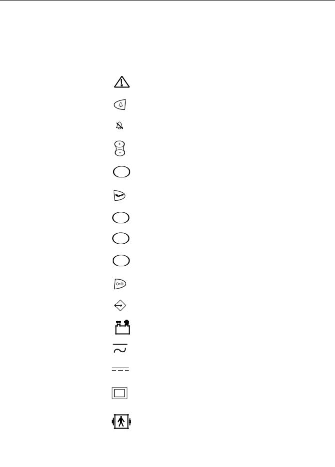
Equipment Symbols
The following symbols are associated with the V100 Vital Signs Monitor.
NOTE: The model of the monitor determines which symbols appear on it.
Attention, consult accompanying documents
Silence
Alarms
+ / - Increase / decrease adjustable settings
Menu
Inflate/Stop
Cycle
History
On/Off
External communications port connector
Battery Power
Charging
External DC power input
Class II equipment according to IEC 60536
Defibrillator-proof type BF equipment
2037106-001 B |
CARESCAPE V100 Vital Signs Monitor |
1-7 |

Introduction: Equipment Symbols
Manufacturer: This symbol is accompanied by the name and the address of the manufacturer.
Manufacturing Date: This symbol is accompanied by the date of the manufacturing.
 European authorized representative.
Packaging label depicting the transportation and storage atmospheric pressure range of 500 to 1060 hPa.
WASTE OF ELECTRICAL AND ELECTRONIC EQUIPMENT (WEEE): This symbol indicates that the waste of electrical and electronic equipment must not be disposed as unsorted municipal waste and must be collected separately. Please contact an authorized representative of the manufacturer for information concerning the decommissioning of your equipment.
The CARESCAPE V100 Vital Signs Monitor is protected IPX1 against vertically falling drops of water and conforms
with the IEC 529 standard at level of IPX1. Vertically falling drops shall have no harmful effects to the Monitor.
1-8 |
CARESCAPE V100 Vital Signs Monitor |
2037106-001 B |

Introduction: Service Requirements
Service Requirements
Follow the service requirements listed below.
Refer equipment servicing to GE Medical Systems Information Technologies authorized service personnel only.
Any unauthorized attempt to repair equipment under warranty voids that warranty.
It is the user’s responsibility to report the need for service to GE Medical Systems Information Technologies or to one of GE’s authorized agents.
Failure on the part of the responsible individual, hospital or institution using this equipment to implement a satisfactory maintenance schedule may cause undue equipment failure and possible health hazards.
Regular maintenance, irrespective of usage, is essential to ensure that the equipment will always be functional when required.
Equipment ID
The following graphic illustrates the components of the monitor’s serial number.
GEMS IT Global Serial Number Format
13Digit
# # # # # # # # # # # # #
Misc. : Prototype, refurbish, etc.
Manufacturing site
Sequential serial number (up to 9999)
Fiscal week
Year
3-character product code
Intended Audience
This manual is intended for service representatives and technical personnel who maintain, troubleshoot, or repair this equipment.
2037106-001 B |
CARESCAPE V100 Vital Signs Monitor |
1-9 |

Introduction: Service Policy
Intended Use
General Use
The V100 Monitor is intended to monitor one patient at a time in a clinical setting.
Federal law (U.S.A.) restricts this device to sale by or on the order of a physician.
To ensure patient safety, use only parts and accessories manufactured or recommended by GE Medical Systems Information Technologies. Parts and accessories used shall meet the requirements of EN60601.1.1.
Disposable devices are intended for single use only. They should not be reused.
Periodically, and whenever the integrity of the monitor is in doubt, test all functions.
Related Manuals
Manual |
Title |
2036991-001 CARESCAPE V100 Vital Signs Monitor Operator’s Manual
Service Policy
The warranty for this product is enclosed with the product in the shipper carton. All repairs on products under warranty must be performed or approved by Product Service personnel. Unauthorized repairs will void the warranty. Only qualified electronics service personnel should repair products not covered by warranty.
Service Contracts
Extended warranties can be purchased on most products. Contact your Sales
Representative for details and pricing.
Assistance
If the product fails to function properly, or if assistance, service or spare parts are required, contact Customer Support. Before contacting Customer Support, it is helpful to attempt to duplicate the problem and to check all accessories to ensure that they are not the cause of the problem. If you are unable to resolve the problem after checking these items, contact GE Medical Systems Information Technologies. Prior to calling, please be prepared to provide:
product name, model number, and serial number
a complete description of the problem
1-10 |
CARESCAPE V100 Vital Signs Monitor |
2037106-001 B |
Introduction: Service Policy
If repair parts or service are necessary, you will also be asked to provide:
the product serial number
the facility's complete name, address, and account number
a purchase order number if the product is to need of repair or when you order spare parts
the facility's GE Medical Systems Information Technologies account number, if possible
the appropriate part number for spare or replacement parts
Service
If your product requires warranty, extended warranty or non-warranty repair service, call Customer Support and a representative will assist you. To facilitate prompt service in cases where the product has external chassis or case damage, please advise the Customer Support representative when you call.
The Customer Support representative will record all necessary information and will provide you with a Return Merchandise Authorization Number (RMA). Prior to returning any product for repair, you must have a RMA number. Contact GE Medical Systems Information Technologies.
Packing Instructions
Follow these recommended packing instructions.
Remove all hoses, cables, sensors, and power cords from the monitor before packing.
Pack only the accessories you are requested to return; place them in a separate bag and insert the bag and the product inside the shipping carton.
Use the original shipping carton and packing materials, if available.
If the original shipping carton is not available:
Place the product in a plastic bag and tie or tape the bag to prevent loose particles or materials from entering openings such as hose ports.
Use a sturdy corrugated container to ship the product; tape securely to seal the container for shipping.
Pack with 4 to 6 in. of padding on all sides of the product.
Insurance
Insurance is at the customer's discretion. The shipper must initiate claims for damage to the product.
2037106-001 B |
CARESCAPE V100 Vital Signs Monitor |
1-11 |

Introduction: Disposal of Product Waste
Service No Charge Rental
A no charge rental unit is provided at no charge during the warranty period of the product when we perform the repair service.
GE Medical Systems Information Technologies pays the shipping charges for a loaner sent to the customer for product repairs under the warranty.
Rental units are available in non-warranty situations.
The customer pays the shipping charges to return a rental.
All loaners provided to customers must be returned within the specified time stated on the loaner agreement or a rental fee will be incurred.
Repair Parts
Repair parts can be ordered from GE Medical Systems Information Technologies:
Via phone: 1-800-558-7044, or
Via FAX: 1-800-421-6841
Exchange replacement assemblies such as Circuit Board Assemblies also are available; ask the Customer Support representative for details.
Please allow one working day for confirmation of your order. All orders must include the following information.
Facility's complete name, address, and phone number
FAX number
Your purchase order number
Your GE Medical Systems Information Technologies account number
Disposal of Product Waste
As you use the V100 Monitor, you will accumulate solid wastes that require proper disposal or recycling. These include batteries, patient applied parts, and packaging material.
Batteries
CAUTION
Do not incinerate batteries.
The sealed, rechargeable backup battery contains lead and can be recycled. The rechargeable memory battery is of the Sealed Lead Acid form. Discharge this battery prior to disposal. Place the battery in packaging which electrically isolates its contents. Do not puncture or place the battery in a trash compactor. Do not incinerate the battery or expose it to fire or high temperatures. Dispose in accordance with regional body controlled guideline.
1-12 |
CARESCAPE V100 Vital Signs Monitor |
2037106-001 B |

Introduction: Disposal of Product Waste
Patient Applied Parts
Certain patient applied parts, such as those with adhesive (disposable SpO2
sensors), are intended for single use and should be disposed of properly as medical waste in accordance with regional body controlled guideline.
Other patient applied parts, such as blood pressure cuffs, should be cleaned according to instructions. Inspect reusable applied parts for wear, replace as necessary, and dispose of used product as medical waste in accordance with regional body controlled guideline.
Packaging Material
Retain original packaging materials for future use in storing or shipping the Monitor and accessories. This recommendation includes corrugated shippers and inserts.
Whenever possible recycle the packaging of accessories and patient applied parts.
Monitor
At the end of its service life, the product described in this manual, as well as its accessories, must be disposed of in compliance with the guidelines regulating the disposal of such products. If you have questions concerning disposal of the product, please contact GE Medical Systems Information Technologies or its representatives.
2037106-001 B |
CARESCAPE V100 Vital Signs Monitor |
1-13 |

Introduction: Disposal of Product Waste
1-14 |
CARESCAPE V100 Vital Signs Monitor |
2037106-001 B |
2 Equipment Overview

For your notes
2-2 |
CARESCAPE V100 Vital Signs Monitor |
2037106-001 B |

Equipment Overview: Equipment Description
Equipment Description
The CARESCAPE V100 Vital Signs Monitor provides a small, portable, easy-to-use monitoring alternative for sub-acute hospital and non-hospital settings. The V100 is for use on adult, pediatric, or neonatal patients—one at a time. The battery-operated monitor offers noninvasive determination of systolic blood pressure, diastolic blood pressure, mean arterial pressure, pulse rate, oxygen saturation, and temperature. Monitors are available with or without integrated printers as well as the following parameters and technologies.
NIBP, Pulse: SuperSTAT, Auscultatory, Classic
SpO2: Ohmeda TruSignal, Nellcor, or Masimo
Temperature: Alaris Turbo Temp
The model of the monitor determines which parameters are in your monitor.
Please refer to applicable sections.
Using the V100 Monitor, a clinician can measure, display, and record patient vital sign data that is derived from each parameter. The monitor is also capable of alerting the clinician to changes in the patient’s condition or when it is unable to effectively monitor the patient’s condition. All of the main operations of the V100 Monitor are easy-to-use and only a button-touch away. Please review the factory default settings and, where applicable, enter settings appropriate for your use.
Product Configurations
Each CARESCAPE V100 Monitor is supplied with an accessory pack. The contents of the pack vary according to model. Unpack the items carefully, and check them against the checklists enclosed within the accessory boxes. If an accessory is missing or if an item is in a nonworking condition, contact GE Medical Systems Information Technologies Customer Service immediately.
It is recommended that all the packaging be retained, in case the V100 Monitor must be returned for service in the future.
2037106-001 B |
CARESCAPE V100 Vital Signs Monitor |
2-3 |

Equipment Overview: Basic Components
Basic Components
Buttons
1.Silence button: mutes audible alarms. Any other active alarm that can be acknowledged is also removed whenever this key is pressed. When pressed, the silence icon (bell) lights red to indicate that audible alarms have been silenced for 2 minutes. Alarm silence can be cancelled by pressing the Silence button again.
2.Alarms button: used to view or adjust parameter alarm limit settings.
3.+/- buttons (Plus/Minus): used when you are in the following modes: limit, menu, cycle, and history. When you are in limit or menu setting, pressing the +/- button increases and decreases an adjustable setting. When you are in cycle or history mode, pressing the +/- buttons displays the next or previous cycle selection or entry in the history list, respectively. When you reach the beginning or ending of a list, a negative key-click sounds.
4.Menu button: accesses menu settings that can be adjusted: INFLATE PRESSURE (ADULT and NEONATE), ALARM VOLUME, and PULSE VOLUME.
(Refer to Operating Modes in this section for a description of clinical mode.) NOTE: ADULT indicator encompasses both adult and pediatric patients.
5.SpO2 sensor connector: attach SpO2 cables here.
6.NIBP connector: attach NIBP cuff hoses here.
7.Inflate/Stop button: starts a manual NIBP determination or stop any NIBP determination.
8.Temperature probe holster: stores temperature probe.
9.Cycle button: used to select NIBP mode of manual, auto cycle, or Stat mode.
10.Temperature probe cover storage: stores probe covers.
2-4 |
CARESCAPE V100 Vital Signs Monitor |
2037106-001 B |

Equipment Overview: Front Panel
11.History button: activates the history mode to view stored patient data. The most recent entries are displayed first. Press and hold the button for 2 seconds to clear all entries stored; the adaptive inflate pressure setting returns to the configured setting. Refer to the “History” Section of this manual for more information.
12.Print button: prints currently displayed values or all stored entries when in history mode.
13.On/Off button: controls on/off state of monitor; push for power on and push again for power off.
14.Temperature probe connector: attach temperature probe cable here.
Front Panel
|
Systolic |
|
15 |
|
|
16 |
|
|
|
Diastolic |
|
17 |
|
|
18 |
|
|
19 |
INFLATE PRESSURE |
Pulse Rate |
ALARM VOLUME |
|
|
20 |
PULSE VOLUME |
|
|
|
|
21 |
SpO |
HIGH |
22 |
|
|
|
LOW |
|
23 |
|
|
|
|
HIGH |
MAP/Cuff |
24 |
|
||
LOW |
ADULT |
25 |
|
||
|
NEONATE |
26 |
|
AUTO CYCLE |
27 |
|
|
|
HIGH |
|
28 |
|
|
|
LOW |
HISTORY |
29 |
|
||
|
|
|
|
BATTERY OK |
3028 |
|
3129 |
|
HIGH |
|
|
LOW |
CHARGING |
320 |
|
||
|
Temperature |
|
|
|
331 |
15.Silence icon: silences audible alarms for 2 minutes; silence icon (bell) lights.
16.Systolic window: indicates measured systolic NIBP in mmHg.
17.Diastolic window: indicates measured diastolic NIBP in mmHg.
18.INFLATE PRESSURE indicator: flashes to indicate you are making a change to the inflation pressure. Adjustable for adult/ped and neonate patients.
19.ALARM VOLUME indicator: flashes to indicate you are making a change to the alarm volume.
20.PULSE VOLUME indicator: flashes to indicate you are making a change to the pulse volume.
21.Pulse Rate window: shows pulse rate in beats per minute.
22.SpO2 pulse indicator: flashing red LED bar indicates that pulses are being derived from SpO2 signals.
23.SpO2 window: indicates oxygen saturation in %.
24.MAP/Cuff window: indicates measured mean arterial pressure (MAP) in mmHg and shows cuff pressure during NIBP determination.
2037106-001 B |
CARESCAPE V100 Vital Signs Monitor |
2-5 |

Equipment Overview: Front Panel
25.ADULT indicator: lights to indicate you are making a change to adult/ped NIBP limits or inflation pressure settings.
26.NEONATE indicator: lights to indicate you are making a change to neonate NIBP limits or inflation pressure settings.
27.AUTO CYCLE indicator: lights green to indicate auto mode is the chosen NIBP mode; flashes to indicate you are making a change to the auto mode.
28.Min window: displays the NIBP mode if manual or Stat as well as the cycle time when taking auto NIBP determinations.
29.HISTORY indicator: flashes to indicate you are in history mode.
30.BATTERY OK indicator: lights green to indicate the monitor is operating on battery power and that the battery is sufficiently charged.
31.BATTERY LOW indicator: lights amber to indicate low charge for the battery (45 min or less when solid; 5 min or less when flashing).
32.CHARGING indicator: lights green to indicate presence of external power source and battery charging.
33.Temperature window: lights 4-digit red LED to indicate measured temperature.
2-6 |
CARESCAPE V100 Vital Signs Monitor |
2037106-001 B |
Loading...