

Page 1

Maintaining and
Troub leshooting
Your E-4200
System
Page 2

Maintaining and
Troubleshooting
Your E-4200
System
Part #8503809 MAN US E-4200 TECH REF R0 10/98
In our effort to use nature’s resources efficiently and wisely, we print all manuals on recycled papers that meet the
minimum requirements established by the Federal EPA i n its guidelines f or recycled paper products.
Page 3

Notices
Copyright © 1998 Gateway 2000, Inc.
All Rights Reserved
610 Gateway Drive
N. Sioux City, SD 57049 USA
All Rights Reserved
This publication is protected by copyright and all rights are reserved. No part of it may be reproduced
or transmitted by any means or in any form, without prior consent in writing from Gateway 2000.
The information in this manual has been carefully checked and is believed to be accurate. However ,
changes are made periodically. These changes are incorporated in newer publication editions.
Gateway 2000 may improve and/or change products described in this publication at any time. Due to
continuing system improvements, Gateway 2000 is not responsible for inaccurate information which
may appear in this manual. For the latest product updates, consult the Gateway 2000 web site at
www.gateway.com. In no event will Gateway 2000 be liable for direct, indirect, special, exemplary ,
incidental, or consequential damages resulting from any defect or omission in this manual, even if
advised of the possibility of such damages.
In the interest of continued product development, Gateway 2000 reserves the right to make
improvements in this manual and the products it describes at any time, without notices or obligation.
T r ademark Acknowledgments
AnyKey, black-and-white spot design, CrystalScan, Destination, EZ Pad, EZ Point, Field Mouse, Solo,
TelePath, Vivitron, stylized “G” design, and “You’ve got a friend in the business” slogan are registered
trademarks and GATEWA Y, Gateway Solo, green stylized GA TEWAY, green stylized Gateway logo, and
the black-and-white spotted box logo are trademarks of Gateway 2000, Inc. Intel, Intel Inside logo, and
Pentium are registered trademarks and MMX is a trademark of Intel Corporation. Microsoft, MS, MSDOS, and Windows are trademarks or registered trademarks of Microsoft Corporation. All other
product names mentioned herein are used for identification purposes only, and may be the trademarks
or registered trademarks of their respective companies.
Copyright © 1998 Advanced Logic Research, Inc. (ALR)
All Rights Reserved
9401 Jeronimo
Irvine, CA 92618 USA
All Rights Reserved
This publication is protected by copyright and all rights are reserved. No part of it may be reproduced
or transmitted by any means or in any form, without prior consent in writing from ALR.
The information in this manual has been carefully checked and is believed to be accurate. However ,
changes are made periodically. These changes are incorporated in newer publication editions. ALR
may improve and/or change products described in this publication at any time. Due to continuing
system improvements, ALR is not responsible for inaccurate information which may appear in this
manual. For the latest product updates, consult the ALR web site at www.alr.com. In no event will ALR
be liable for direct, indirect, special, exemplary, incidental, or consequential damages resulting from
any defect or omission in this manual, even if advised of the possibility of such damages.
In the interest of continued product development, ALR reserves the right to make improvements in this
manual and the products it describes at any time, without notices or obligation.
T r ademark Acknowledgments
ALR is a registered trademark of Advanced Logic Research, Inc. All other product names mentioned
herein are used for identification purposes only, and may be the trademarks or registered trademarks
of their respective companies.
Page 4

Contents
Preface ............. ................... .................. .......... .................. .......iii
Conventions used in this guide .............................................................. iv
Safety instructions ................................................................................... v
Additional information sources ............................................................. vi
The Gateway Support Center.......................................................... vi
The System Restoration CD ......................................................... vii
Case Access ................................ ......... ................... ................1
Static electricity precautions ................................................................... 2
Identifying your computer case .............................................................. 3
Opening the case...................................................................................... 4
Removing the desktop case cover ................................................... 4
Removing the mid-tower case cover............................................... 6
Removing the tower case cover....................................................... 7
Replacing the cover................................................................................. 9
Replacing the desktop case cover.................................................... 9
Replacing the mid-tower case cover.............................................. 10
Replacing the tower case cover...................................................... 11
System Componen ts ............................................... ..............13
Locating components ............................................................................ 14
Desktop components...................................................................... 14
Mid-tower components.................................................................. 15
Tower components......................................................................... 16
System board ......................................................................................... 17
I/O connectors........................................................................................ 19
Front panel I/O connections........................................................... 20
Setting the jumpers................................................................................ 21
Recovery mode............................................................................... 22
Replacing the processor ........................................................................ 23
Installing memory.................................................................................. 29
Installing and replacing drives.............................................................. 31
Replacing and installing drives in your desktop computer........... 32
Replacing and installing drives in your mid-tower computer ...... 40
Replacing and installing drives in your tower computer .............. 45
Adding an expansion card..................................................................... 55
Contents i
Page 5

LM81 hardware management .............................................................. 57
Installing LANDesk Client Manager................................................... 58
Replacing the battery ............................................................................ 58
Troubleshooting the battery installation ....................................... 60
Replacing the power supply ................................................................. 60
BIOS Setup .. .................. ................... ......... ................... ..........65
About the BIOS setup utility ................................................................ 66
Using the BIOS setup utility.......................................................... 66
Updating the BIOS................................................................................ 67
Troubleshooting .... ................... ............................ ...................69
Introduction........................................................................................... 70
Troubleshooting checklist .................................................................... 70
Verifying your configuration......................................................... 70
Viewing system resources............................................................. 70
Troubleshooting guidelines........................................................... 71
CD-ROM problems .............................................................................. 72
Hard disk problems............................................................................... 73
Memory/Processor problems ............................................................... 74
Modem problems.................................................................................. 75
Peripheral/Adapter problems................................................................ 76
Printer problems.................................................................................... 78
System problems................................................................................... 79
Video problems..................................................................................... 80
Error messages ...................................................................................... 83
Appendix ............... ......... ................... ................... ...................87
Specifications ........................................................................................ 88
Regulatory Compliance Statements..................................................... 90
Index .......................................................................................93
ii Maint a in ing an d T r oubl esh oo t in g You r E- 42 00 Sys t em
Page 6
Pref ace
Conventions used in this guide .............................. iv
Safety instructions ................................................... v
Additional information sources.............................. vi
Page 7
Con ventions used in this guide
Throughout this guide, you will see the following conventions:
Convention Description
NTER
E
TRL+ALT+DEL
C
Setup
User’s Guide
Important!
Keyboard key names are printed in small
capitals.
A plus sign i ndicat es t hat t he k e ys m ust be
pressed simul taneously.
Commands to be entered, options to
select, and messa ges that appear on you r
monitor are printed in bold.
Names of publ ications and f iles are printed
in italic .
An important note informs you of special
circumstances.
Caution!
Warning!
A caution warns you of possible damage
to equipment or loss of data.
A warning indic at es th e possibility of
personal injury.
iv M aintainin g and Trou bleshooting Your E-4200 System
Page 8

Safety instructions
Observe the following safety instructions when using your system:
Follow all instructions marked on the system and in the
•
documentation.
When the computer is turned off, a small amount of electrical
•
current still runs through the computer. Always unplug the
computer from the electrical outlet before cleaning the system or
opening the computer cover. (Follow the cleaning instructions in
your user’s guide.)
Do not use this product near water or a heat source, such as a
•
radiator or heat register.
Do not spill anything on or into the system. The best way to avoid
•
spills is to avoid eating and drinking near your system.
Make sure you set up the system on a stable work surface.
•
Openings in the computer cabinet are provided for ventilation. Do
•
not block or cover these openings. Make sure you provide adequate
space (at least 12 inches) around the system for ventilation when
you set up your work area. Never insert objects of any kind into the
computer ventilation slots.
Warning!
Do not attempt to service
the syst em yo urs el f except
as explained elsewhere in
the system documentation.
Adjust only those controls
covered in the instructions.
Opening or removing
cove rs ma rk ed “ Do N ot
Remov e” ma y e x po se y ou
to dang er ous el ec t ric al
voltages or other risks.
Refer all servicing of those
compartments to qualified
service pe rson ne l.
Use the voltage setting for your area. The voltage selector switch is
•
set at the factory to the correct voltage.
As a safety feature, this system is equipped with a 3-wire power
•
cord to ensure that the product is properly grounded when in use.
The plug will only fit into a grounding-type outlet. If you are
unable to insert the plug into an outlet, contact an electrician to
install the appropriate outlet.
Do not walk on the power cord or allow anything to rest on it.
•
If you use an extension cord with this system, make sure the total
•
ampere ratings on the products plugged into the extension cord do
not exceed the extension cord ampere rating. Also, the total ampere
requirements for all products plugged into the wall outlet must not
exceed 15 amperes.
Preface v
Page 9

There is a danger of explosion if the CMOS (complementary
•
metal-oxide semiconductor) battery is replaced incorrectly.
Replace the battery with the same or equivalent type recommended
by the manufacturer. Dispose of used batteries according to the
manufacturer’s instructions.
Unplug the system from the wall outlet and refer servicing to
•
qualified personnel if:
• The power cord or plug is damaged.
• Liquid has been spilled into the system.
• The system does not operate properly when the operating
instructions are followed.
• The system was dropped or the cabinet is damaged.
• The system’s performance changes.
Ad ditional inf ormation sour ces
Along with this manual and your user’s guide, you can find additional
information by using the following sources.
The Gate wa y Support Center
Log on to the Gateway Support Center at www.gateway.com/support to
access information about your system or other Gateway products. Some
types of information you can access are:
Hardware driver (including BIOS) and software
•
application updates
An expanded glossary
•
Technical tips
•
Service Agreement information
•
Technical documents and component information
•
Frequently Asked Questions (FAQ)
•
Online access to Tech Support
•
vi Maintaining and Troubleshooting Your E-4200 System
Page 10

The Syste m Restor ation CD
The System Restoration CD included with your system can be used to:
Restore your Windows 95 or Windows 98 operating system
•
Install hardware drivers for Windows 95, Windows 98, and
•
Windows NT
Reinstall selected software applications, such as LANDesk Client
•
Manager or McAfee Virus Scan
View or install component online documentation
•
Instructions for each operating system are provided with the System
Restoration CD.
Preface vii
Page 11

viii Mai nt ain in g an d T roub l esh oot in g Your E- 42 00 Syste m
Page 12

Chapter 1:
Case Access
Static electricity precautions ................................... 2
Identifying your computer case............................... 3
Opening the case...................................................... 4
Replacing the cover ................................................. 9
1
Page 13

Caution!
Prevent elec tro st at ic
damage to yo ur syste m b y
fol lo wi ng st at i c elect r icit y
precautions every time you
open y ou r comp ut er ca se .
Warn ing!
To avoid exposure to
dange r ous el ec tr ic al
vol t ages a nd mo v in g pa rts,
turn off your computer and
unplug the power cord
bef ore re movi ng the system
cover.
Static electricity precautions
Static electricity can permanently damage electronic components in your
computer. When opening your computer case, always perform the
following procedure:
Wear a grounding wrist strap (available at most electronics stores).
1.
Turn off the system power.
2.
Touch the back of the power supply fan, located on the back of the
3.
case, to discharge any static electricity.
Unplug all power cords from AC outlets.
4.
Remove the computer case cover.
5.
Follow these precautions to avoid electrostatic damage to your system
components:
Avoid static-causing surfaces such as plastic and styrofoam in your
•
work area.
Remove the parts from their antistatic bags only when you are
•
ready to use them. Do not lay parts on the outside of antistatic bags
since only the inside of the bag provides antistatic protection.
Always hold cards by their edges and their metal mounting bracket.
•
Avoid touching components on the cards and the edge connectors
that connect to expansion slots.
Never slide cards or other parts over any surface.
•
2 Mainta in i ng and Trou bl es hoot in g Y our E-4 200 Sy stem
Page 14
Identifying your computer case
This chapter includes the procedures for opening and closing the case for
each of the four models shown below. Refer to the section appropriate to
your case style.
Mid-to wer case
Tower case
Desktop ca se
Case Access 3
Page 15

Opening the case
The system is available in three basic models:
Desktop
•
Important!
Only q uali fi ed pe rson ne l
should open the system for
mainte na nc e . You need a
grounding wrist strap and a
Phillips screwdriver to
remove the computer’s
cover.
Mid-tower
•
Towe r
•
The desktop case has a removable top panel and a removable front bezel.
The mid-tower and tower cases have two removable side panels, and a
removable front bezel.
To install or remove components inside your desktop system, you must
remove the top cover panel. For some procedures you must remove the front
bezel. For the mid-tower and tower systems, you must remove the panel on
the right side (as seen from the back of the system). For some procedures
you must remove the left side panel and the front bezel.
Your system includes an anti-intrusion switch on the case. If you attempt to
open the case without turning off the system, your system automatically
turns off.
Because the components inside your computer are extremely sensitive to
static electricity, be sure to follow the precautions for avoiding static
electricity damage at the beginning of this chapter.
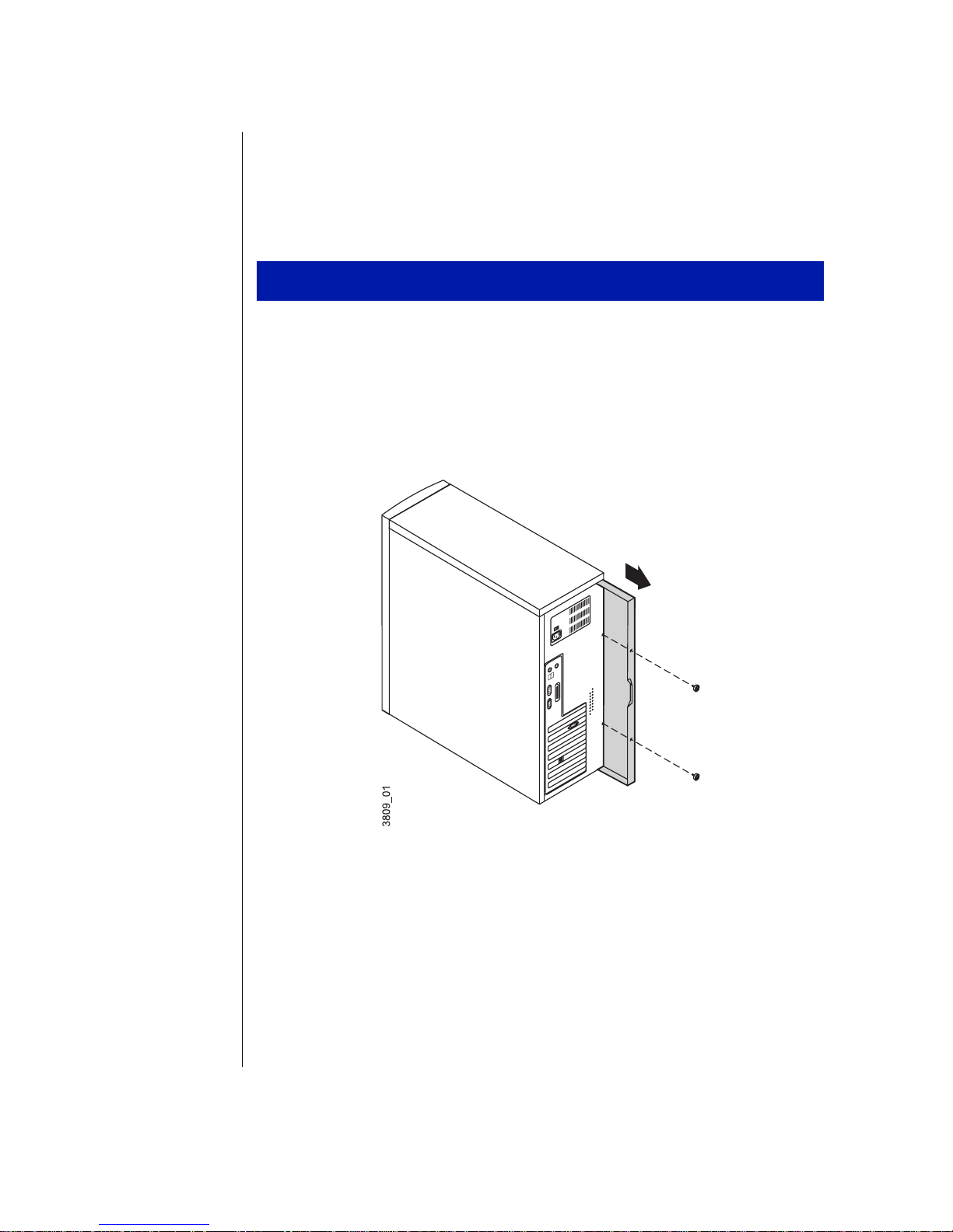
Remo ving the deskt op case cov er
You need a grounding wrist strap and a Phillips screwdriver to open the
case.
To remove the desktop case cover
Turn off the computer and disconnect all power cords.
1.
Remove the two thumbscrews at the back of the computer and set
2.
them aside.
4 Mainta in i ng and Trou bl es hoot in g Y our E-4 200 Sy stem
Page 16
Slide the top cover panel back, lift it up, and set it aside.
3.
If you are replacing or adding a drive you may also need to remove the
4.
bezel. To do this, lift up on the tabs at each end of the top edge of the
case bezel and pull the bezel away from the system frame.
Case Access 5
Page 17
Remo ving the mid-to wer case cov er
You need a grounding wrist strap and a Phillips screwdriver to open the
case.
To remove the mid-tower case cover
Turn off the system and disconnect all power cords.
1.
Remove the thumbscrews on the right side of the back of the
2.
computer.
Remove the right side panel by pulling on the handgrip between the
3.
thumbscrew holes.
If you are replacing externally accessible drives, remove the two
4.
Phillips screws on the other side of the back of the computer and
remove the side panel. Both side panels must be removed to access the
four screws that attach such devices to the drive cage.
Remove the four screws that attach the 5.25-inch CD-ROM drive to
5.
the drive cage. Pull the CD-ROM drive out half-way. This allows the
bezel to be removed.
6 Mainta in i ng and Trou bl es hoot in g Y our E-4 200 Sy stem
Page 18
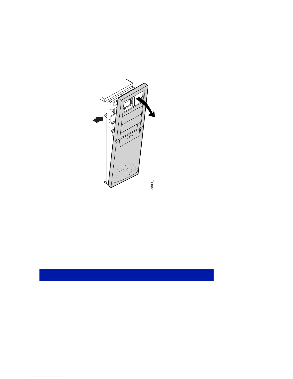
If you are installing externally accessible drives or replacing existing
6.
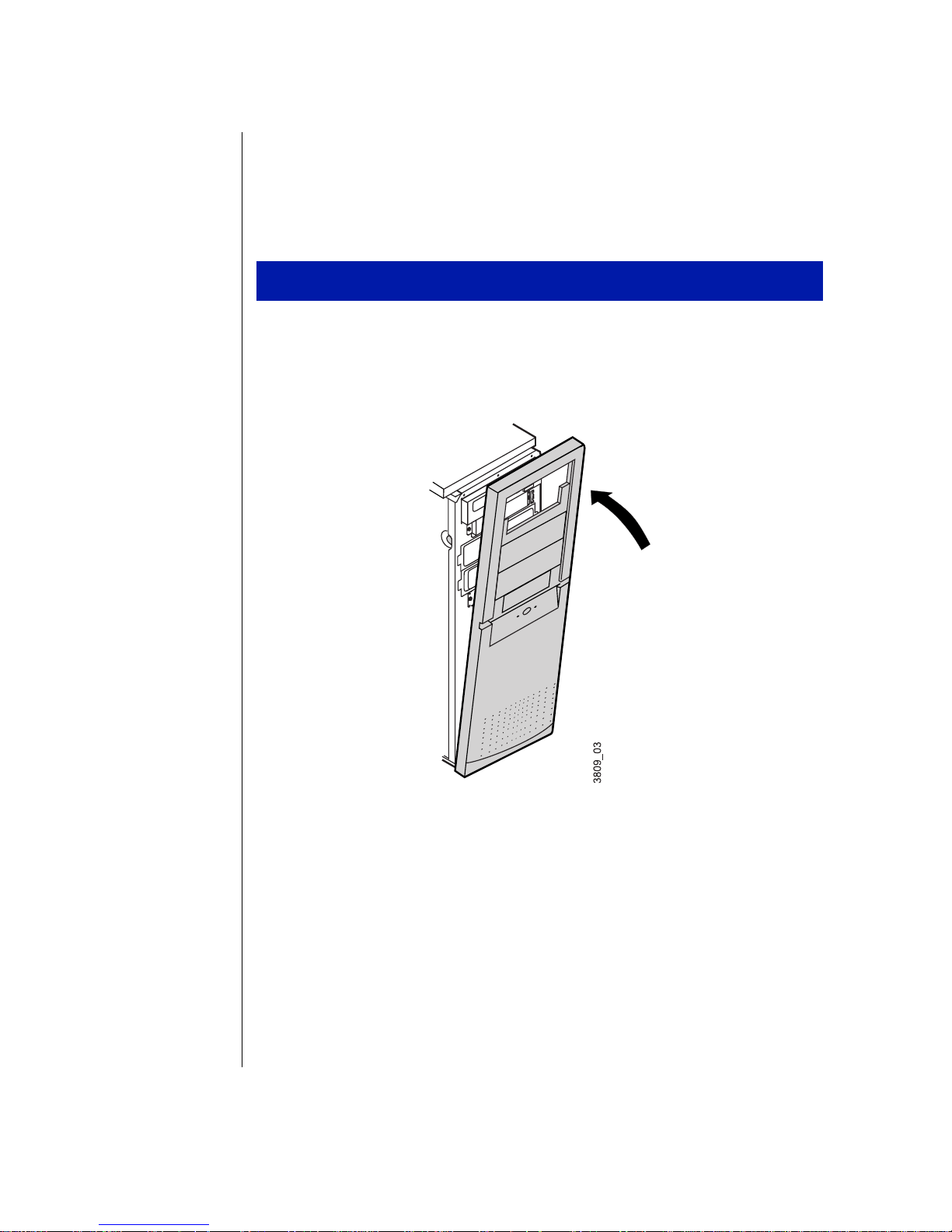
ones, remove the bezel by inserting a finger into each of the two
circular openings at the front of the computer, pushing in on the spring
clips, and pulling the upper portion of the bezel slightly forward to
release it.
Lift the bezel up until the bottom tabs release.
7.
Pull the bezel away from the computer.
8.
Removing the tower cas e cov er
You need a grounding wrist strap and a Phillips screwdriver to open the
case.
To open the case
Turn off the system and disconnect all power cords.
1.
Case Access 7
Page 19
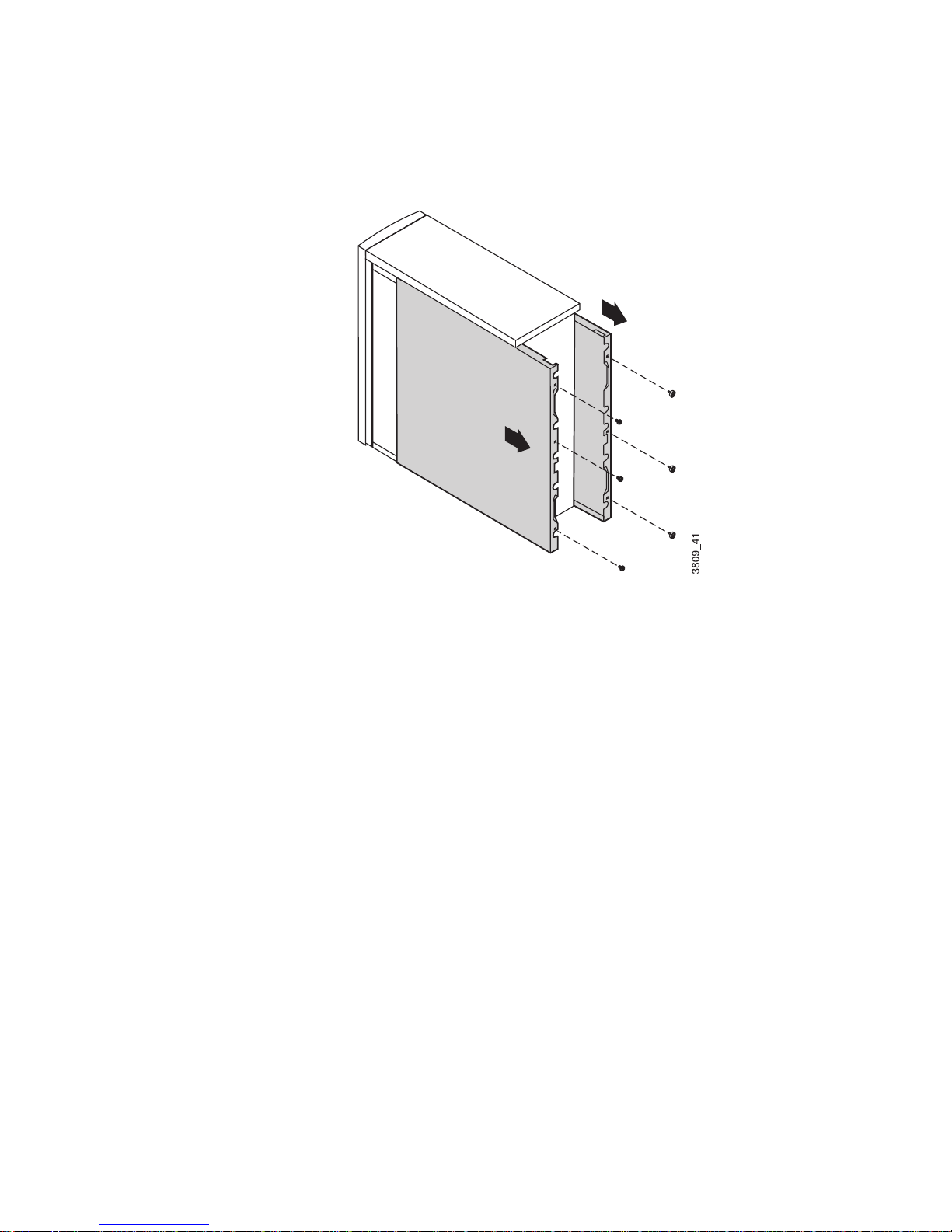
With the back of the computer facing you, remove the three
2.
thumbscrews and the three Phillips screws that attach the side panels
to the chassis.
Right side
panel
Left si de
panel
Grasp the right panel by the handholds on the panel and slide the panel
3.
towards you until the panel comes off the chassis.
Grasp the left panel by the handholds on the panel and slide the panel
4.
towards you until the panel comes off the chassis.
8 Mainta in i ng and Trou bl es hoot in g Y our E-4 200 Sy stem
Page 20
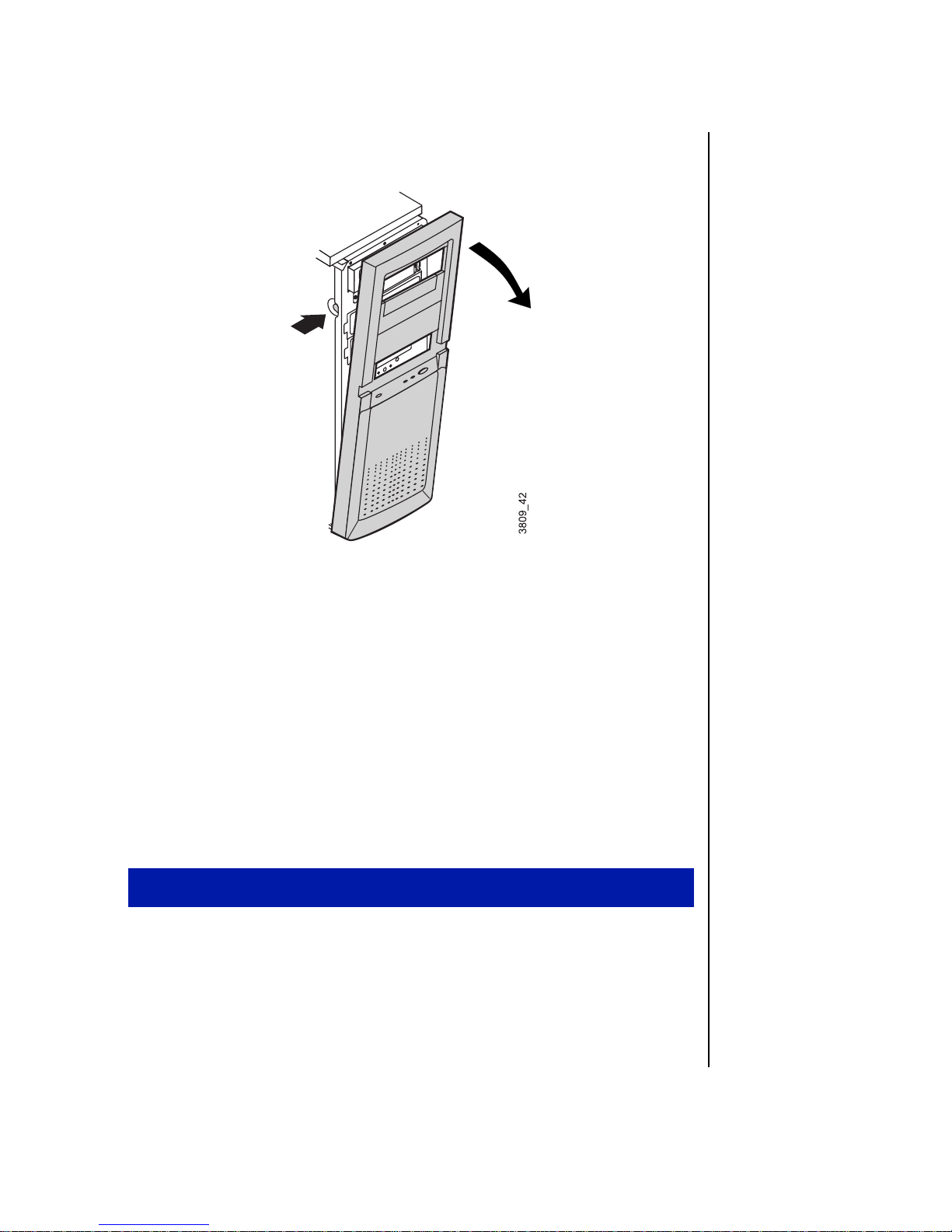
Push in the tabs on each side of the front bezel and pull the bezel off
5.
the chassis.
1. Press i n tab s
on both sides
of chass is
2. Pull off
bezel
Replacing the cover
Replace the cover as soon as you finish installing or removing components
so that dust and dirt (which could damage the computer) do not collect
inside the computer.
Replac ing the desktop c ase cov er
You need a grounding wrist strap and a Phillips screwdriver to close the
case.
To replace the desktop case cover
If you removed the case bezel, replace the bezel by inserting it at the
1.
bottom of the system frame and snapping the top tabs back in place.
Slide the top panel cover back on to the case frame.
2.
Secure the top panel cover with the thumbscrews you removed.
3.
Case Access 9
Page 21
Replacin g the mid-tow er case cov er
You need a grounding wrist strap and a Phillips screwdriver to close the
case.
To replace the mid-tower case cover
If you installed additional external drives, then you must replace the
1.
bezel. Hook the tabs at the bottom of the front bezel into the slots in
the chassis. Then push the bezel into the chassis until the spring clips
snap the bezel in place.
Place the left side panel onto the chassis and slide the panel toward the
2.
front of the chassis. Replace the two screws that attach the panel to the
chassis.
Place the right side panel onto the chassis, making sure the panel fits
3.
into the rails on the chassis. Slide the panel toward the front of the
chassis until the tabs on the panel fit under the rim of the chassis.
Replace the two thumbscrews that attach the panel to the chassis.
4.
10 Maintainin g and Tro ubleshooting Your E-4200 System
Page 22

Replacing the tower case cov er
You need a grounding wrist strap and a Phillips screwdriver to close the
case.
To close the tower case
Hook the tabs at the bottom of the front bezel into the slots in the
1.
chassis. Then push the bezel toward the chassis until the bezel snaps in
place.
1. Hoo k ta bs
on both sid es
into chassis
2. Push be ze l
toward
chassi s
Case Access 11
Page 23
Place the left side panel on to the chassis and slide the panel toward the
2.
front of the chassis. Make sure the tab at the front of the panel fits
under the edge of the chassis.
Tabs
Replace the three screws that attach the left side panel to the chassis.
3.
Place the right side panel on to the chassis, making sure the panel fits
4.
into the rails on the chassis. Slide the panel toward the front of the
chassis until the tabs on the panel fit under the edge of the chassis.
Replace the three thumbscrews that attach the right side panel to the
5.
chassis.
12 Maintainin g and Tro ubleshooting Your E-4200 System
Page 24
Chapter 2:
System
Components
Locating components ............................................ 14
System board ......................................................... 17
I/O connectors........................................................ 19
Setting the jumpers ................................................ 21
Replacing the processor......................................... 23
Installing memory.................................................. 29
Installing and replacing drives .............................. 31
Adding an expansion card..................................... 55
LM81 hardware management............................... 57
Installing LANDesk Client Manager.................... 58
Replacing the battery............................................. 58
Replacing the power supply .................................. 60
2
Page 25
Locating components
The following figures and lists identify the components inside the
computer.
Desktop c omponents
The following components are inside your desktop system (illustration
shown from top view of system).
A
B
System board
A
Power supply
B
5.25-inch drive bay (top)
C
Two 3.25-inch internal drive bays (bottom)
D
5.25-inch external drive bay (top)
E
3.25-inch external drive bay (bottom)
F
C
DEF
14 Maintainin g and Tro ubleshooting Your E-4200 System
Page 26
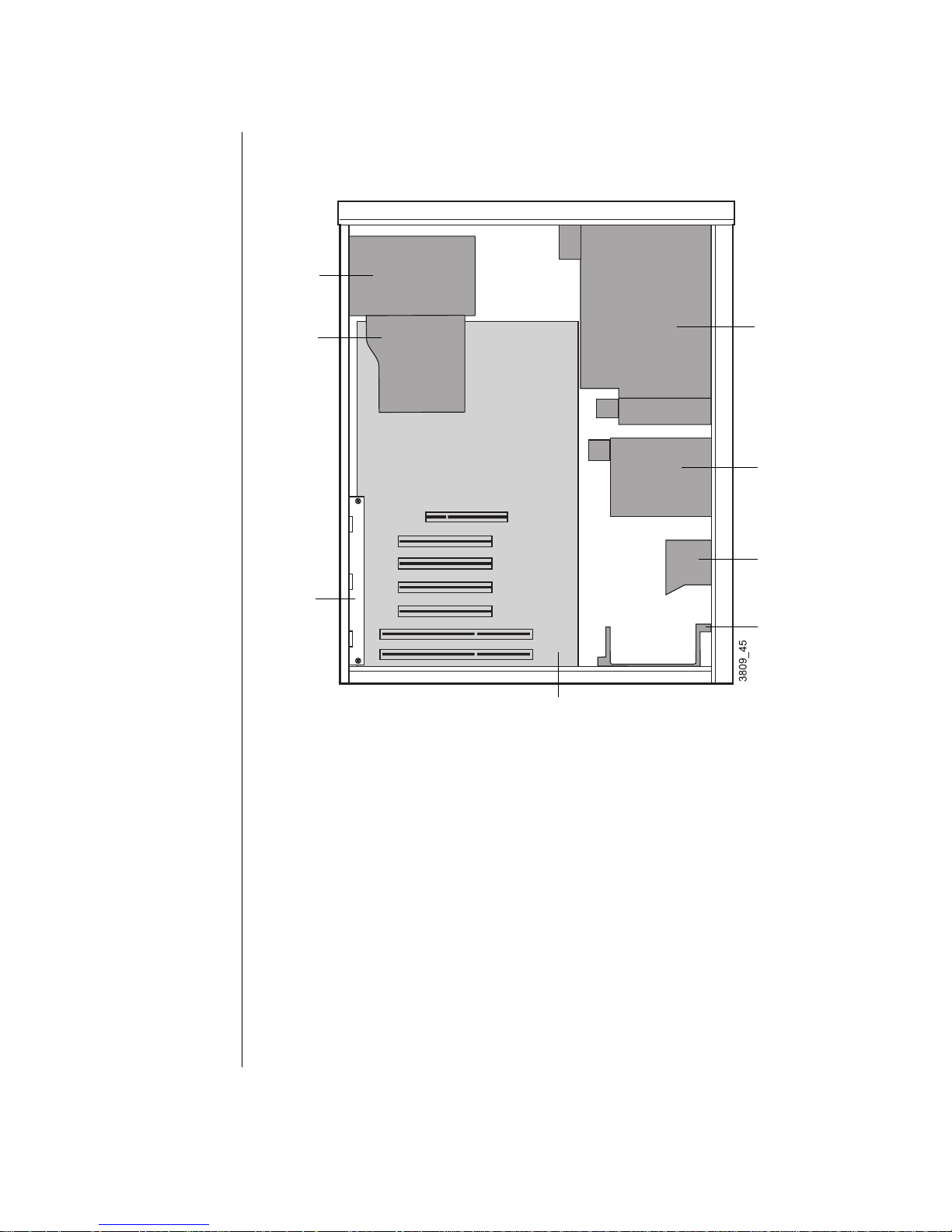
Mid-to wer components
The following components are inside your mid-tower system.
5.25-inch bay
A
3.5-inch bay
F
E
D
Power Supply
A
5.25 -in ch bay
5.25- inc h bay
3.5-i nch bay
B
C
Externally accessible drive bays
B
Internal 3.5-inch hard drive bays
C
Stability bar
D
System board
E
Fan duct
F
System Components 15
Page 27
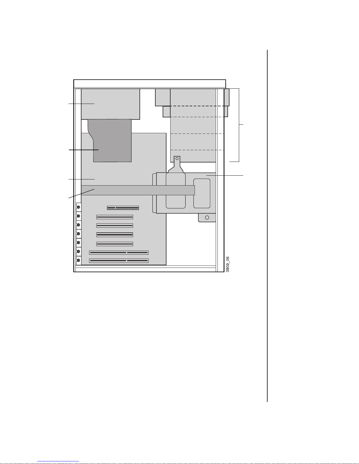
Towe r components
The following components are inside your tower system.
H
G
F
Top drive cage
A
A
B
C
D
E
Middle hard drive cage
B
Add-in card guide (included in some systems)
C
Bottom hard drive cage
D
System board
E
Add-in card bracket
F
Fan duct
G
Power supply
H
16 Maintainin g and Tro ubleshooting Your E-4200 System
Page 28
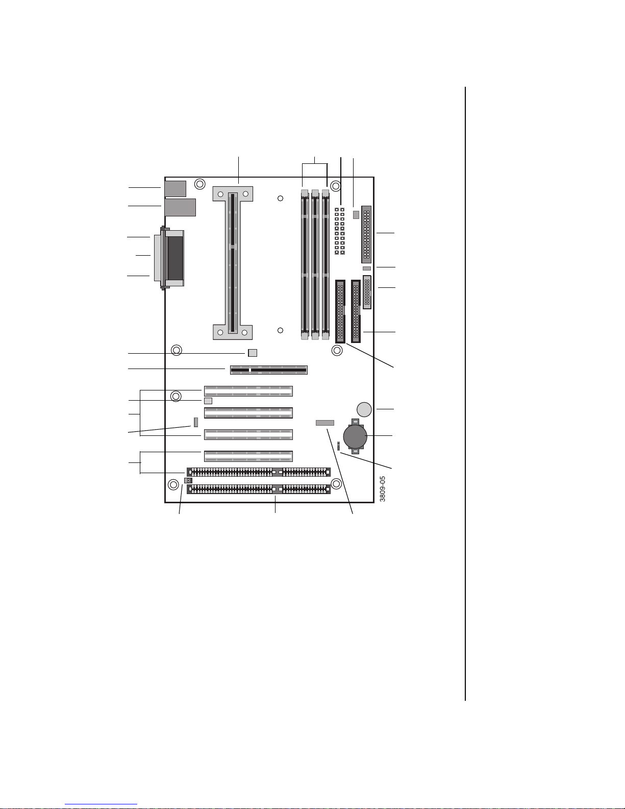
System board
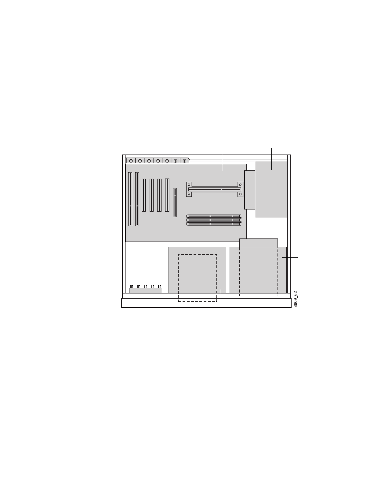
The following figure and list identify system board components.
ABCD
Z
Y
U
R
Q
X
W
V
T
S
P
O
N
M
E
F
G
H
I
J
K
L
Slot 1 connector
A
DIMM sockets (3)
B
Power connector
C
Fan 1 connector (to fan on power supply)
D
Diskette drive connector
E
SCSI LED header
F
System Components 17
Page 29

Front panel connector
G
Primary IDE connector
H
Secondary IDE connector
I
Onboard speaker
J
Battery
K
Configuration jumper (J7B1)
L
Front panel USB header
M
ISA slot
N
Wake-on-Ring (WOR) connector
O
Shared ISA/PCI slot (1)
P
Wake-on-LAN (WOL) connector
Q
PCI slots (3)
R
Chassis intrusion switch connector
S
AGP connector
T
Fan 3 connector
U
Serial port B
V
Parallel port
W
Serial port A
X
USB ports (2)
Y
Mouse and Keyboard ports
Z
18 Maintainin g and Tro ubleshooting Your E-4200 System
Page 30
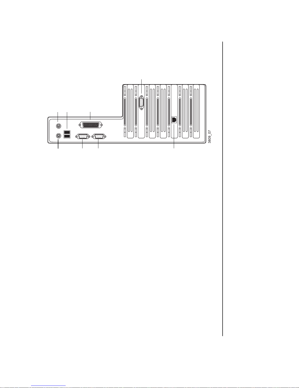
I/O connectors
The following figure and list identify connectors on the back of the
computer.
D
A
BC
GH
PS/2 mouse port
A
USB ports
B
Parallel port
C
Video port
D
RJ-45 LAN connector
E
Serial port B
F
Serial port A
G
Keyboard port
H
EF
System Components 19
Page 31

F ront panel I/O connections
The front panel I/O connector block lets you connect devices such as
speakers and power management accessories. Although these connections
are not covered in this guide, the illustration is provided for your reference.
20 Maintainin g and Tro ubleshooting Your E-4200 System
Page 32

Setting the jumpers
The system board jumper (J7B1) lets you clear passwords, set the
processor/bus speed, and recover the BIOS. The table below shows the
settings required to perform those tasks, and the following text provides
step-by-step instructions for each mode.
J7B1 Mode Jumper Setting Action When Set
Normal 1-2 Normal operation
Configure 2-3 Adds a Maintenance
menu to Setup utility with
options to clear
passwords and set
processor/ bus speeds
Recov ery No jumper Causes system to
attempt BIOS upd ate or
recovery from diskette
The following figure shows the location of the jumper on the system board.
Important!
Some p rocessors are
design ed so th at y our
system ca n aut oma tica lly
detect the pro cessor spee d.
For other processors, you
must manually enable the
system to de te ct th e
proces so r spee d. See
page 27 for more
inf ormation.
3
J7B1
1
System Components 21
Page 33

Recovery mode
The J7B1 jumper lets you recover the BIOS if it has become corrupted.
To recover the BIOS
Log onto the internet.
1.
Download the correct BIOS file from the Technical Support web site.
2.
Extract the contents of the BIOS file you downloaded, and copy the
3.
contents onto a bootable diskette.
Turn off the system and disconnect the power cord.
4.
Open the case, observing the “Static electricity precautions” on
5.
page 2.
Remove the pin on the J7B1 jumper and store it in a safe place. You
6.
will replace the jumper on pins 1-2 in Step 12.
Close the case, as described in Chapter 1.
7.
Place the bootable diskette containing the BIOS files into drive A.
8.
Reconnect the power cord and turn on the system to recover the BIOS.
9.
When you hear two beeps, the BIOS has been successfully recovered.
Turn off the system again, eject the diskette from drive A, and
10.
disconnect the power cord.
Open the case, observing the “Static electricity precautions” on
11.
page 2.
Place the jumper back on pins 1-2 on the J7B1 jumper.
12.
Close the case, as described in Chapter 1, reconnect the power cord,
13.
and turn on the system.
22 Maintainin g and Tro ubleshooting Your E-4200 System
Page 34

Replacing the processor
The system is compatible with the Intel® Pentium® II 66 and 100 MHz
front-side bus (FSB) processors.
The system board will support the following processor/bus configurations:
266/66
•
300/66
•
333/66
•
350/100
•
400/100
•
450/100
•
It is critical that a heat sink be installed on each Pentium processor.
When replacing a processor, order a Pentium processor upgrade kit. The kit
includes the Pentium processor, a heat sink, and a disposable electrostatic
discharge (ESD) wrist strap.
Some of the steps below are specific to your desktop, mid-tower or tower
computer. Please skip the step if it does not apply to your system.
To replace the processor
Turn off the system and disconnect the power cord.
1.
Open the case, observing the “Static electricity precautions” on
2.
page 2.
Remove the stability bar (mid-tower only). Skip to step 4 if your
3.
system does not have a stability bar:
System Components 23
Page 35

Using a Phillips screwdriver, remove the screw that attaches the
A.
stability bar to the chassis.
Stability
bar
Screw
Hard drive
cage
Lift the bar slightly and slide it towards the front of the chassis until
B.
the bar clears the hard drive cage. Lift the bar out of the chassis.
Remove the fan duct (mid-tower and tower only). Skip to step 5 if your
4.
system does not have a fan duct:
Grasp the sides of the fan duct.
A.
24 Maintainin g and Tro ubleshooting Your E-4200 System
Page 36

Gently squeeze the duct until the side tabs unlatch from the power
B.
supply.
Fan
duct
Lift the duct out of the chassis.
C.
Identify your processor bracket type. The processor is attached to the
5.
system board with either a top bracket or a bottom bracket.
Top
bracket
If your processor is attached by a top bracket:
6.
Using a flat-bladed screwdriver, remove the screws from the top
A.
bracket. Lift off the bracket.
Bottom bracket
System Components 25
Page 37

Pull the processor up and out.
B.
Top
brac ket
Push the new processor into the slot until it is fully seated.
C.
Place the top bracket over the processor and replace the two screws.
D.
If your processor is attached by a bottom bracket:
7.
Remove the DIMMs on the system board that block access to the
A.
bottom processor bracket. Gently push out the plastic socket clamps
on each end of the DIMMs. Then carefully lift the DIMMs out of
their sockets. Store the DIMMs in static-free bags.
26 Maintainin g and Tro ubleshooting Your E-4200 System
Page 38

Push in the tabs on the outside edges of the bottom bracket and pull
B.
the bracket away from the processor.
Bottom bracket
Press in the two latches at the top of the processor, and pull the
C.
processor up and out.
Push the new processor into the slot until it snaps into place.
D.
Push the support bracket back into the base of the processor until it
E.
snaps into place.
Replace any DIMMs you removed.
F.
Replace the stability bar and fan duct if applicable.
8.
Close the case, as described in Chapter 1.
9.
Plug in the power cord and turn on the computer and monitor.
10.
Check to see if your system has automatically detected the processor
11.
speed.
When you see the Gateway logo on the screen, press TAB to display
A.
the system messages.
Check the processor speed displayed on the screen. If the correct
B.
speed is shown, your system has automatically detected the
processor speed.
If an incorrect speed is shown, you need to open a special menu in
your system’s Setup program to manually set the correct processor
speed. Setting system board jumper J7B1 opens this menu.
System Components 27
Page 39

If the processor speed is not detected automatically, set the speed
12.
manually:
Turn off your system and unplug all power cords.
A.
Open the system case.
B.
Locate jumper J7B1, as shown in the following figure.
C.
3
J7B1
1
Take the jumper shunt off pins 1 and 2 on jumper J7B1 and place
D.
the shunt over pins 2 and 3.
Close the computer case, reconnect the power cords, and turn on the
E.
system. As your system starts, the Setup program opens and a
Maintenance screen appears.
When the Maintenance screen appears, set the processor speed.
F.
Save the configuration and exit Setup.
Turn off the system, disconnect the power cords, and open the case.
G.
Move the jumper shunt on the J7B1 jumper back to its normal
H.
position over pins 1 and 2.
28 Maintainin g and Tro ubleshooting Your E-4200 System
Page 40

Close the case, reconnect the power cord, and turn on the system.
I.
Your system now detects the speed of the new processor.
Installing memory
The Synchronous Dynamic Random Access Memory (SDRAM) Dual
In-line Memory Modules (DIMMs) supported by your system board
conform to the following standards:
3.3 V, 168-pin unbuffered SDRAM
•
16 MB and 32 MB (16 bit technology)
•
64 MB and 128 MB (64 bit technology)
•
Single- or double-sided configurations
•
384 MB maximum system memory
•
When you are installing DIMMs, keep the following in mind:
You can use 16-MB, 32-MB, 64-MB, and 128-MB DIMMs in any
•
combination, band, or order to expand the SDRAM up to 384 MB.
No jumper settings are required for the memory size or type
•
because this information is automatically detected by the BIOS.
This system board requires 4-clock DIMMs with a clock latency of
•
2 (CL2), otherwise known as CL24-clock DIMMs.
To install DIMMs
Turn off the system and disconnect the power cord.
1.
Open the case, observing the Static Electricity precautions in
2.
Chapter 1.
System Components 29
Page 41

Pull open the socket clamps on each side of the DIMM socket.
3.
Insert the DIMM into the socket and align the two notches in the
4.
DIMM with the two notches in the DIMM socket.
Gently press the DIMM into the socket until it doesn’t move any
5.
farther. (Inserting the DIMM automatically locks each of the socket
clamps on each end of the DIMM.)
Caution!
Never try to remove a
DIMM without releasing the
clamps. You may break the
socket, causing serious
damage.
Close the case, as described in Chapter 1.
6.
Reconnect the power cord and turn on the system.
7.
To remove DIMMs
Gently push out the plastic socket clamps on each end of the DIMM.
1.
The DIMM should pop up slightly from the socket.
30 Maintainin g and Tro ubleshooting Your E-4200 System
Page 42

Carefully lift the DIMM out of the socket.
2.
Store the DIMM in a static-free container.
3.
Installing and replacing drives
The standard configuration for your computer includes a 5.25-inch IDE
CD-ROM drive, a 3.5-inch IDE hard drive, and a 3.5-inch diskette drive.
As you prepare to install drives, keep the following in mind:
Before you install a drive, see the drive’s documentation for
•
information on configuring the drive, setting any jumpers on the
drive, and attaching cables to the drive.
If you are installing a drive that uses an expansion card controller,
•
install the expansion card before you install the drive.
The computer’s integrated IDE connectors can support four IDE
•
drives. The computer’s integrated diskette connector can support a
diskette drive.
Important!
To remove and install
drives, you need a
grounding wrist strap and a
Phillips screwdriver. If you
remove a drive, make sure
to plac e it in an ant is t atic
bag.
IDE hard drives can be configured as single, master, or slave. IDE
•
CD-ROM drives can be configured as master or slave. Use the
drive-select jumpers on the drives to configure IDE drives as
follows: If only one drive is attached to the controller cable,
configure the drive as single if it is a hard drive or master if it is a
CD-ROM drive. If two drives of any type are attached to the cable,
configure one as master and one as slave.
If you want to install SCSI drives, you need to install a SCSI
•
controller card to operate the drives and may need to install
software drivers.
You may need to configure the drives you install through the
•
system’s Setup program. Press F1 at start up to access the Setup
program.
System Components 31
Page 43

Replacin g and installing drive s in your
desktop computer
Your desktop computer contains the following drive bays:
One 3.5-inch drive bay that can be accessed from outside the
•
computer.
Two 5.25-inch drive bay that can be accessed from outside the
•
computer.
Two 3.5-inch drive bays that are not accessible from outside the
•
computer.
Replacing the 3.5-inch diskette drive in your desktop
computer
In your computer, a 3.5-inch diskette drive attaches to a metal mounting
bracket. For the location of the 3.5-inch diskette drive brackets, see the
section “Desktop components” on page 14.
To replace the 3.5-inch diskette drive
Turn off the system and disconnect the power cord.
1.
Open the case, observing the “Static electricity precautions” on
2.
page 2.
Locate the combination 3.5-inch drive/5.25-inch drive cage.
3.
Disconnect the power and data cables from the back of both drives,
4.
noting their locations and orientations. (You will reconnect these
cables after you install the new drive.)
32 Maintainin g and Tro ubleshooting Your E-4200 System
Page 44
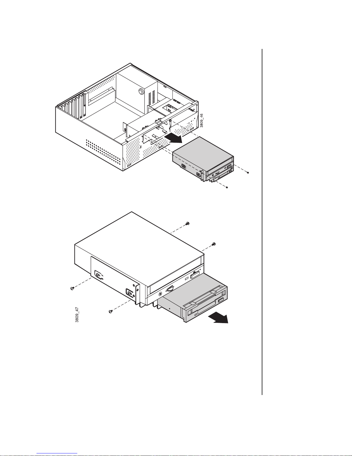
Remove the drive cage from the case.
5.
Remove the drive from the cage.
6.
Secure the new drive in the cage.
7.
Connect the power and data cables to the 3.5-inch and 5.25-inch
8.
drives, making sure the cables match their original positions.
Reinstall the drive cage in the case.
9.
Connect the power and data cables to the drive.
10.
System Components 33
Page 45

Close the computer case as described in Chapter 1.
11.
Reconnect the power cord and turn on the system.
12.
If the system does not recognize the new drive, see
“Peripheral/Adapter problems” on page 76.
Installing a 3.5-inch hard driv e in your desktop computer
The hard disk is secured to a metal mounting cage, which enables the drive
to be easily installed and removed from the case.
To install a hard disk drive
Turn off the system and disconnect the power cord.
1.
Open the case, observing the “Static electricity precautions” on
2.
page 2.
Locate the 5.25-inch drive cage to the right of the case and do one of
3.
the following:
• If the drive bay is empty, remove the metal drive bay cover
from the front of the 5.25-inch drive bay.
• If a drive is installed in the 5.25-inch drive bay, disconnect the
data and power cables from the drive, noting their locations
and orientations. (You will reconnect these cables after you
install the new drive.)
34 Maintainin g and Tro ubleshooting Your E-4200 System
Page 46

Remove the 5.25-inch drive cage from the case. The hard drive cage is
4.
underneath.
Disconnect the hard disk data and power cables from the hard disk,
5.
noting their locations and orientations. (You will reconnect these
cables when you install the new hard disk.)
Remove the hard disk cage from the case.
6.
System Components 35
Page 47

Configure the new drive by following your drive documentation.
7.
Do one of the following:
8.
If you are replacing the hard drive that is installed in the cage,
•
remove the drive from the cage and install the new drive in its
place.
If you are adding an additional hard drive, install the drive in the
•
empty bay of the drive cage.
Reinstall the drive cages into the case.
9.
Close the case as describe in Chapter 1.
10.
Plug in the power cable and peripherals.
11.
Turn on the computer.
12.
If the system does not recognize the new drive, see “Hard disk
problems” on page 73 for troubleshooting information.
Replacing the CD-ROM drive in y our desktop computer
A 5.25-inch drive is secured to the same metal mounting cage as the
3.5-inch drive. A 5.25-inch drive, such as a CD or DVD drive, can be
installed in this location.
To replace the CD-ROM drive in the center bay
Turn off the system and disconnect the power cord.
1.
Remove the cover side panels, observing the “Static electricity
2.
precautions” on page 2.
Locate the combination 3.5-inch drive/5.25-inch drive cage.
3.
Disconnect the power and data cables from the back of both drives,
4.
noting their locations and orientations. (You will reconnect these
cables after you install the new drive.)
36 Maintainin g and Tro ubleshooting Your E-4200 System
Page 48

Remove the drive cage from the case.
5.
Remove the drive from the cage.
6.
Secure the new drive in the cage.
7.
Connect the power and data cables to the drives, making sure the
8.
cables match their original positions. Configure the drive by following
your drive documentation.
Reinstall the drive cage into the case.
9.
System Components 37
Page 49

Close the computer case (see “Replacing the desktop case cover” on
10.
page 9 for further instructions).
Plug in the power cable and peripherals.
11.
Turn on the computer.
12.
Installing or replacing an additional 5.25-inch drive in
your desktop computer
You can install another 5.25-inch drive, such as a CD or DVD drive, in the
drive expansion bay to the right of the case.
To install a 5.25-inch drive in the expansion bay
Turn off the system and disconnect the power cord.
1.
Remove the cover side panels, observing the “Static electricity
2.
precautions” on page 2.
Do one of the following:
3.
If a drive is not yet installed in the drive bay, remove the metal drive
•
bay cover from the front of the bay. Also, remove the plastic drive
bay cover from the front bezel.
If you are replacing a drive, disconnect the power and data cables
•
from the drive, noting their locations and orientations. (You will
reconnect these cables after you install the new drive.)
38 Maintainin g and Tro ubleshooting Your E-4200 System
Page 50

Remove the drive cage from the case.
4.
If you are replacing a drive, remove it from the mounting cage.
5.
Secure the new drive in the cage.
6.
Install the drive cage in the case.
7.
Connect the power and data cables to the drive. Configure the drive by
8.
following your drive documentation.
Close the computer case (see “Replacing the desktop case cover” on
9.
page 9 for further instructions).
System Components 39
Page 51

Plug in the power cable and peripherals.
10.
Turn on the computer.
11.
Replacin g and installing drive s in your
mid-to wer computer
Your mid-tower computer contains the following drive bays:
Three 3.5-inch drive bays that can be accessed from outside the
•
computer.
Two 5.25-inch drive bays that can be accessed from outside the
•
computer.
Three 3.5-inch drive bays that are not accessible from outside the
•
computer.
Replacing a 3.5-inch diskette drive in the mid-tower
computer
In your computer, a 3.5-inch diskette drive attaches to a metal mounting
bracket. For the location of the 3.5-inch diskette drive brackets, see the
section “Mid-tower components” on page 15.
To replace a 3.5-inch diskette drive
Turn off the system and disconnect the power cord.
1.
Open the case, observing the “Static electricity precautions” on
2.
page 2.
If you are replacing a drive, remove the drive:
3.
Disconnect the power and data cables from the back of the drive.
•
Remove the four screws that attach the drive to the drive bracket.
•
The screws can be accessed through the chassis side panels.
Push the drive out of the chassis through the bezel.
•
If you are adding a drive into a bay that is empty:
4.
40 Maintainin g and Tro ubleshooting Your E-4200 System
Page 52

Remove the bezel.
A.
Push out the EMI shield in the bay.
B.
Remove the plastic drive bay cover on the front bezel. For
C.
information on removing the bezel, see the section “Removing the
mid-tower case cover” on page 6.
Place the new drive into the drive bracket through the front bezel.
5.
Secure the drive to the mounting bracket using four screws.
6.
Connect the power and data cables to the drive.
7.
Close the case, as described in Chapter 1.
8.
Reconnect the power cord and turn on the system.
9.
If the system does not recognize the new drive, see
“Peripheral/Adapter problems” on page 76.
System Components 41
Page 53

Installing or replacing a 3.5-inch hard drive in your
mid-tower computer
In your computer, a 3.5-inch hard drive attaches to a metal mounting
bracket. You can easily remove the bracket and install a new drive. For the
location of the 3.5-inch hard drive bracket, see the “Mid-tower
components” on page 15.
To install a 3.5-inch hard drive
Turn off the system and unplug the power cord.
1.
Open the case, observing the “Static electricity precautions” on
2.
page 2.
Disconnect the cables from the back of any drives installed in the hard
3.
drive bracket.
Remove the stability bar (see page 24).
4.
Remove the three screws that attach the hard drive bracket. Support
5.
the bracket with your hand as you remove the screw inside the chassis.
42 Maintainin g and Tro ubleshooting Your E-4200 System
Page 54

Slide the bracket up to unhook the tabs on the bracket from the slots in
6.
the chassis. Lift the bracket out of the chassis.
If you are replacing a hard drive, remove the screws that attach the
7.
drive to the drive cage and remove the drive.
Slide the new hard drive into the bracket and attach the drive to the
8.
drive cage.
Replace the hard drive cage in the chassis, sliding it down until the
9.
tabs on the bracket hook into the slots on the chassis. Attach the
bracket to the chassis with the three screws you removed in step 5.
Replace the stability bar.
10.
Connect the power and controller cables to the drives in the bracket.
11.
Replace the system cover (see “Replacing the cover” on page 9 for
12.
instructions). Plug in the power cord and turn on the computer.
Configure the drive as needed in Setup.
13.
If the system does not recognize the new drive, see “Hard disk
problems” on page 73 for troubleshooting information.
System Components 43
Page 55

Installing a CD-ROM or other 5.25-inch drive in your
mid-tower computer
The 5.25-inch drive bay can be used to install a CD-ROM drive, diskette
drive, or other 5.25-inch device.
To install a CD-ROM or other 5.25-inch drive
Turn off the system and disconnect the power cord.
1.
Remove the cover side panels, observing the “Static electricity
2.
precautions” on page 2.
If you are replacing a drive, remove it from the chassis:
3.
Disconnect the cables from the back of the drive.
•
Remove the four screws that attach the drive to the chassis. The
•
screws can be accessed through the chassis side panels.
Slide the drive out of the chassis through the front of the bezel.
•
If you are installing a drive in an empty drive bay:
4.
Remove the bezel
A.
Push out the EMI shield in the bay.
B.
Remove the plastic drive bay cover on the front bezel. For
C.
information on removing the bezel, see the section “Identifying
your computer case” on page 3.
44 Maintainin g and Tro ubleshooting Your E-4200 System
Page 56

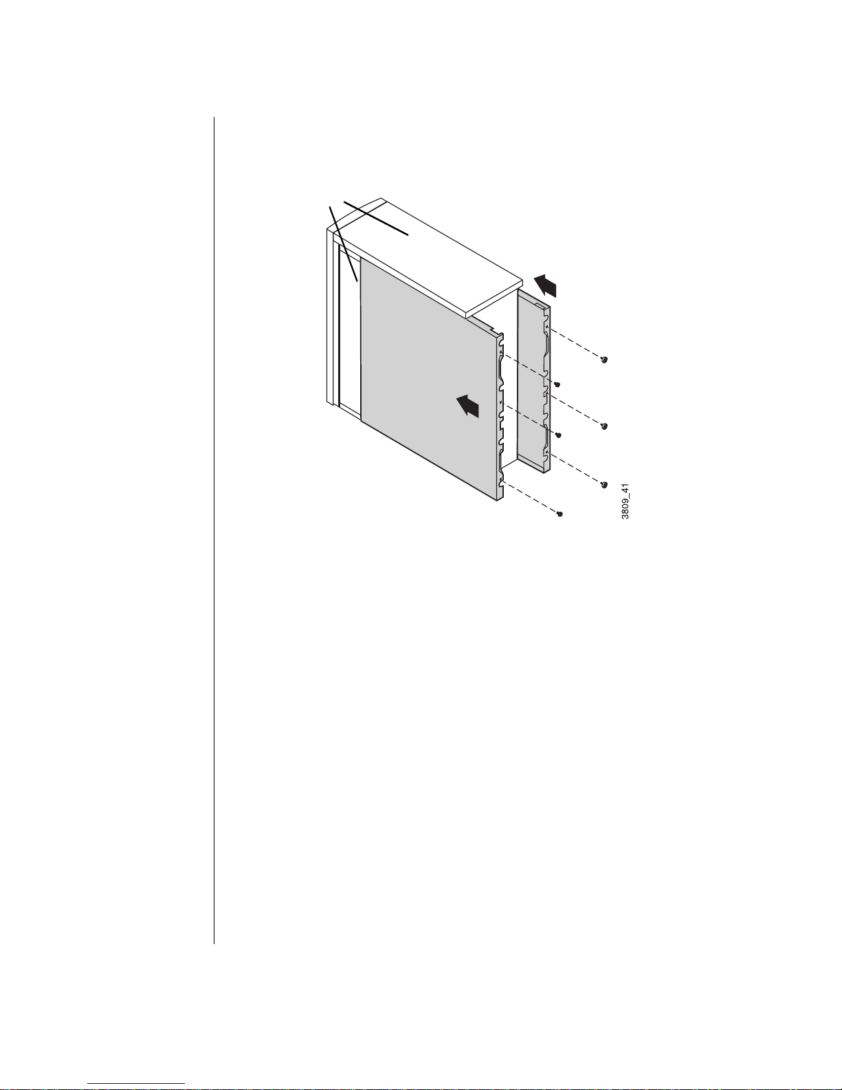
Slide the new 5.25-inch drive into the bay through the front bezel.
5.
Attach the drive to the chassis with the four screws.
6.
Connect the power and data cables to the back of the drive. (See drive
7.
documentation for proper jumper settings and connector orientation.)
Close the case (see “Replacing the mid-tower case cover” on page 10
8.
for further instructions).
Plug in the power cable and peripherals.
9.
Turn on the computer.
10.
Replacing and installing drives in your tower
computer
Your tower computer contains the following drive bays:
Top drive cage: five drives (5.25-inch and 3.5-inch) that can be
•
accessed from outside the system.
Middle drive cage: two full-height or three half-height 3.5-inch
•
hard drives that are not accessible from outside the system.
System Components 45
Page 57

Bottom drive cage: one full-height or two half-height 3.5-inch hard
•
drives that are not accessible from outside the system.
Installing or replacing a CD-R OM drive or diskette driv e
in the top drive cage of your tower computer
You can install a 5.25-inch CD-ROM and 3.5-inch diskette drive the top
drive cage.
To install a drive in the top drive cage
Turn off the system and disconnect the power cord.
1.
Open the case, observing the “Static electricity precautions” on
2.
page 2.
If a drive is installed in the bay you want to use, remove the drive:
3.
Disconnect data cables from the back of the drive.
•
Remove the four screws (two on either side of the drive) that attach
•
the drive to the drive cage.
Push the drive out of the chassis through the bezel.
•
46 Maintainin g and Tro ubleshooting Your E-4200 System
Page 58

If an EMI shield and slot cover are in the bay you want to use, remove
4.
them:
Push the EMI shield out through the front of the chassis.
•
Push the slot cover out through the back of the bezel.
•
System Components 47
Page 59

Slide the new drive into the system through the front of the chassis.
5.
Install the four screws that attach the drive to the drive cage.
6.
Close the case, as described in Chapter 1.
7.
Reconnect the power cord and turn on the system.
8.
If the system does not recognize the new drive, see
“Peripheral/Adapter problems” on page 76.
Installing a 3.5-inch hard driv e in your tow er computer
In your computer, a middle and bottom drive cage together can hold five
3.5-inch hard drives. For the location of the 3.5-inch hard drive cage, see the
“Tower components” on page 16.
48 Maintainin g and Tro ubleshooting Your E-4200 System
Page 60

Installing or replacing hard drives i n the middle drive
cage
You can install up to three 3.5-inch hard drives in the middle drive cage.
To install a drive in the middle drive cage
Turn off the system and unplug the power cord.
1.
Remove the left side panel of the case, observing the “Static electricity
2.
precautions” on page 2.
If any drives are installed in the drive cage, disconnect the cables from
3.
the back of the drives.
If your system includes an add-in card guide, remove it:
4.
Remove any long add-in cards attached to the card guide.
A.
Remove the screw that attaches the add-in card guide to the chassis
B.
and then slide the card guide out of the computer.
Add-in car d gu ide
(in so me
system s)
System Components 49
Page 61

Remove the three screws that attach the middle drive cage to the
5.
chassis. Support the cage with your hand as you remove the last screw.
Then slide the drive cage out of the chassis.
Middl e ha rd
driv e cage
If a drive is in the bay of the cage that you want to use, remove the
6.
screws that attach the drive to the cage and remove the drive.
50 Maintainin g and Tro ubleshooting Your E-4200 System
Page 62

Slide the new drive into the cage and attach the drive to the cage with
7.
four screws.
Slide the drive cage into the chassis, making sure to hook the tabs on
8.
the cage into the slots on the chassis. Replace the three screws that
attach the cage to the chassis.
Important!
When you reinstall the
middle drive cage, make
sure you do not set the
cage on the cables
attached to the control
panel.
Slots
Tab
Connect the cables to the drives in the cage. If a card guide is included
9.
in your system, replace the add-in card guide and any add-in cards you
removed.
System Components 51
Page 63

Close the computer case (see “Replacing the tower case cover” on
10.
page 11 for instructions). Plug in the power cord and turn on the
computer.
If the system does not recognize the new drive, see “Hard disk problems”
on page 73 for troubleshooting information.
Installing hard drives in the bottom drive cage
You can install 3.5-inch hard drives in the bottom drive cage.
To install a drive in the bottom drive cage
Turn off the system and unplug the power cord.
1.
Remove the right side panel of the case (see page 7 for instructions),
2.
observing the “Static electricity precautions” on page 2.
If any drives are installed in the drive cage, disconnect the cables from
3.
the back of the drives.
If your system includes an add-in card guide, remove it:
4.
Remove any long add-in cards attached to the card guide.
A.
Remove the screw that attaches the add-in card guide to the chassis
B.
and then slide the card guide out of the computer.
52 Maintainin g and Tro ubleshooting Your E-4200 System
Page 64

Remove the three screw that attach the drive cage to the chassis. Then
5.
slide the cage forward and lift it out of the chassis.
Bottom hard
driv e cag e
If a drive is in the bay of the cage that you want to use, remove the
6.
screws that attach the drive to the cage and remove the drive.
Slide the new drive into the cage with the bottom of the drive facing
7.
up. Attach the drive to the cage with four screws.
System Components 53
Page 65

Slide the drive cage into the chassis, making sure to hook the tabs on
8.
the cage into the slots on the chassis. Replace the three screws that
attach the cage to the chassis.
Slots
Connect the cables to the drives in the bracket.
9.
If a card guide is included in your system, replace the add-in card
10.
guide and any add-in cards you removed.
Close the case as described in Chapter 1.
11.
Plug in the power cord and turn on the computer.
12.
If the system does not recognize the new drive, see “Hard disk problems”
on page 73 for troubleshooting information.
54 Maintainin g and Tro ubleshooting Your E-4200 System
Page 66

Adding an expansion card
The E-4200 system board has seven expansion slot connectors:
One shared ISA/PCI slot
•
Three PCI local-bus slots
•
One ISA slot
•
One AGP slot
•
The E-4200 system board accepts three types of expansion cards: ISA, PCI,
and AGP.
Some ISA expansion cards have jumpers or switches that set interrupts and
I/O addresses. They come with instructions that explain how to set them to
avoid hardware conflicts. Follow the instructions carefully.
Refer to the appropriate system board illustration earlier in this chapter for
the correct installation location.
Important!
Your desktop sys tem on ly
supports half-lengt h AGP
cards.
To add an expansion card
Set any jumpers and switches on the card, if required in the card
1.
instructions.
Turn off the system and disconnect the power cord.
2.
Open the case, observing the “Static electricity precautions” on
3.
page 2.
System Components 55
Page 67

If applicable, remove the two screws that attach the add-in card bracket
4.
to the case and remove it.
Add-in card bracket
(tower system only)
Locate an available slot.
5.
Remove and retain the screw securing the expansion port cover to the
6.
rear panel. Keep the port cover for reinstallation in case you ever need
to remove the card.
Firmly insert the edge of the expansion card into the slot.
7.
56 Maintainin g and Tro ubleshooting Your E-4200 System
Page 68

After seating the card firmly, secure it to the chassis by installing the
8.
screw you removed in Step 6 through the mounting bracket at the end
of the card.
Replace the add-in card bracket.
9.
Connect cables to the card (see card documentation for proper jumper
10.
settings and cable orientation)
Close the case, as described in Chapter 1.
11.
Reconnect the power cord and turn on the system.
12.
It may be necessary to reconfigure your system after installing some
expansion cards. You may also need to install software that came with the
card. Check the card documentation for additional information.
LM81 hardware management
LM81 is an integrated data acquisition system that lets you monitor the
status of your system hardware. Monitored information includes internal
temperature, fan speed, voltage, and chassis intrusion (to alert you in case of
tampering). The features of the hardware management system can be
®
accessed through LANDesk
system health indicator.
Client Manager, which provides a quick
System Components 57
Page 69

Installing LANDesk Client
Manager
Intel’s LANDesk Client Manager is the Desktop Management Interface
(DMI) solution that is already loaded on your system. LANDesk Client
Manager lets you monitor your system for critical situations that may need
your attention. It also lets your system administrator remotely inventory and
manage systems on your network.
To install LANDesk Client Manager
In the C:\DMI folder, double-click the Setup icon to launch the
1.
®
InstallShield
Follow the instructions that appear on your screen. If you are prompted
2.
for a password during the installation process, enter LOWTCO.
LANDesk Client Manager comes with complete electronic documentation
and on-line help. Refer to these documents and Help for any LANDesk
concerns.
wizard.
Replacing the battery
The battery provides power for the system real-time clock and CMOS
RAM, which holds the system configuration information.
If your battery is failing you may notice your system clock slowing down
and giving you the incorrect time. If so, open the Setup utility and write
Caution!
There is a danger of
explosion if the battery is
incor rect l y repl a ced.
Replace the battery only
with the same or equivalent
type recommended by the
manufacturer. Dispose of
used batteries according to
the man ufacturer’s
instruct io ns .
58 Maintainin g and Tro ubleshooting Your E-4200 System
down all the values in the menus and submenus before replacing the battery.
Replacing the battery resets the Setup utility to its default values.
Restart the computer and start the BIOS Setup program by pressing F1
1.
when you are prompted to do so.
To replace the battery
Page 70

Write down the CMOS values from the Main Setup utility screen so
2.
you can reenter them after you replace the battery. (For more
information about the setup program, see “Using the BIOS setup
utility” on page 66.)
Turn off the system and disconnect the power cord.
3.
Open the case, observing the “Static electricity precautions” on
4.
page 2.
Locate the battery on the system board (see “System board” on
5.
page 17). The battery is circular and has the positive pole mark (+) on
the top.
Using a flat-bladed screwdriver, carefully remove the battery from its
6.
socket on the system board.
Press the new battery in the socket with the positive pole up. Be sure
7.
you have pressed the battery down far enough for it to contact the base
of the socket.
Close the case, as described in Chapter 1.
8.
Reconnect the power cord and turn on the system.
9.
Enter the setup program and verify that the system configuration is
10.
correct using the data you recorded in Step 2.
If the CMOS data is not correct, change the information in the setup
screens as necessary.
System Components 59
Page 71

Troub leshooting the batt ery installat ion
If you have problems after installing the new battery, try each of the items
listed below, replacing the cover and restarting the computer after each try.
Turn off the system and ensure that all exterior cables are attached
•
to the correct connectors and secured.
Check to be sure that all power switches are on. If the system is
•
plugged into a power strip or surge protector, be sure it is turned on
also.
Enter the BIOS Setup program and compare the settings on the
•
screen with your notes or the system hardware manuals. Correct
any discrepancies.
Turn off the system, remove the cover, and verify that all cables
•
inside the case are attached securely. Also, make sure that the
colored cable edges are aligned correctly and that the connectors
didn’t miss any pins. Disconnect and reconnect the cables, and then
replace the cover carefully so as not to disturb any cables.
Turn off the system, remove the cover and, if you have the proper
•
test equipment, verify that the new battery has power. (It is
possible, although highly unlikely, that your new battery is
defective.)
When everything works properly, close the case as described in Chapter 1,
reconnect the power cord, and turn on the system.
Replacing the po wer suppl y
Please observe the following instructions for removing the power supply
and installing a new one
Installing a power supply in your desktop computer
Turn off the system and unplug the power cord.
1.
Open the case, as described in Chapter 1. Observe the “Static
2.
electricity precautions” on page 2.
60 Maintainin g and Tro ubleshooting Your E-4200 System
Page 72

Disconnect all power supply cables from internal devices, including
3.
the main power supply connection to the system board.
Remove the four screws on the back of the chassis that attach the
4.
power supply to the chassis.
Lift the power supply out of the chassis.
5.
Check the red voltage switch on the back of the new power supply. Be
6.
sure it is set to the correct voltage for your area.
Important!
To remove and install the
power supply, you need a
grounding wrist strap and a
Phillips screwdriver.
Line up the holes in the new power supply with the screw holes in the
7.
back of the chassis.
Replace the four screws on the back of the chassis that attach the
8.
power supply to the chassis.
Reconnect the power supply cables.
9.
Replace the system cover (see “Replacing the desktop case cover” on
10.
page 9 for instructions). Plug in the power cord and turn on the
computer.
System Components 61
Page 73

Important!
To remove and install the
power supply, you need a
grounding wrist strap and a
Phillips screwdriver.
If the system does not work correctly, make sure that you installed the
power supply correctly and connected the power supply cable to the
power connector on the system board. Check that the voltage
connector on the back of the power supply is set correctly.
Installing a power supply in your mid-tower computer
Turn off the system and unplug the power cord.
1.
Open the case, as described in Chapter 1. Observe the “Static
2.
electricity precautions” on page 2.
Disconnect all power supply cables from internal devices, including
3.
the main power supply connection to the system board.
Remove the fan duct (see page 24 for more information on removing
4.
the duct).
Remove the four screws on the back of the chassis that attach the
5.
power supply to the chassis.
Support the power supply with your hand and remove the screw inside
6.
the chassis that attaches the power supply.
62 Maintainin g and Tro ubleshooting Your E-4200 System
Page 74

Lift the power supply out of the chassis.
7.
Check the red voltage switch on the back of the new power supply. Be
8.
sure it is set to the correct voltage for your area.
Line up the holes in the new power supply with the screw holes in the
9.
back of the chassis.
Replace the four screws on the back of the chassis and the one screw
10.
inside the chassis that attach the power supply to the chassis.
Replace the fan duct.
11.
Reconnect the power supply cables.
12.
Replace the system cover (see “Replacing the cover” on page 9 for
13.
instructions). Plug in the power cord and turn on the computer.
If the system does not work correctly, make sure that you installed the
power supply correctly and connected the power supply cable to the
power connector on the system board. Check that the voltage
connector on the back of the power supply is set correctly.
Installing a power supply in your tower computer
Turn off the system and unplug the power cord.
1.
Open the case, as described in Chapter 1. Observing the static
2.
electricity precautions on “Static electricity precautions” on page 2.
Disconnect all power supply cables from internal devices, including
3.
the main power supply connection to the system board.
Remove the fan duct (see page 24 for more information on removing
4.
the fan duct).
System Components 63
Page 75

Remove the four screws on the back of the chassis that attach the
5.
power supply to the chassis.
Support the power supply with your hand and remove the two screws
6.
on the side of the chassis that attach the power supply.
Lift the power supply out of the chassis.
7.
Check the red voltage switch on the back of the new power supply. Be
8.
sure it is set to the correct voltage for your area.
Line up the holes in the new power supply with the screw holes in the
9.
back of the chassis.
Replace the four screws on the back of the chassis and the two screws
10.
on the side of the chassis.
Replace the fan duct.
11.
Reconnect the power supply cables.
12.
Replace the system cover (see “Replacing the tower case cover” on
13.
page 11 for instructions). Plug in the power cord and turn on the
computer.
If the system does not work correctly, make sure that you installed the
power supply correctly and connected the power supply cable to the power
connector on the system board. Check that the voltage selector on the back
of the power supply is set correctly.
64 Maintainin g and Tro ubleshooting Your E-4200 System
Page 76

Chapter 3:
BIOS Setup
About the BIOS setup utility................................. 66
Updating the BIOS ................................................ 67
3
Page 77

About the BIOS setup utility
The computer’s BIOS has a built-in program that lets you set many basic
system characteristics. These settings are stored and saved even when the
power is off. This chapter contains information about this setup utility and
is intended to serve as a guide so that you can make changes to your system
BIOS when necessary.
Using the BIO S setup utility
The computer’s BIOS has a built-in setup utility that lets you configure
several basic system characteristics. The settings are stored in
battery-backed RAM and are retained even when the power is off.
To enter the setup utility, restart the system and then press
F1 when
prompted on screen during the startup process. Upon entering setup, the
Main Setup screen opens.
BIOS Setup Utility
Main Advanced Security Power Boot Exit
Item Specific Help
BIOS Version
Processor Type
Processor Speed
Front Side Bus Speed
Cache Ram
System Memory
Memory Bank 0
Memory Bank 1
Memory Bank 2
Cache ECC Support:
F1 Help ↑↓Select Item -/+ Change Values F9 Setup Default
ESC Exits
Language:
System Time:
System Date:
←→
Select Menu Enter Select > Sub-Menu F10 Save and Exit
4M4PBox1.15A.xxx.xxx
Pentium® II
xxx MHz
xxx KB
xxx MB
[Not Installed]
[Not Installed]
64 MB SDRAM
[English (US)]
[Disabled]
[xx:xx:22]
[xx/xx]
Select the current
default language used
by BIOS
As you select items on the main menu and in submenus, you will see
specific information related to the current selection in the Item Specific
Help box. Refer to the Help box for information about the menu options.
The command bar at the bottom of the screen shows the keystrokes
necessary to access help, navigate through the menus, and perform other
functions.
66 Maintainin g and Tro ubleshooting Your E-4200 System
Page 78

The main screen has the following menu selections at the top of the screen:
Main gives you access to basic information and settings related to
•
your system hardware and configuration.
Advanced gives you access to information and settings for system
•
resources, hardware, and system configuration.
Security gives you access to settings related to system access
•
passwords.
Power gives you access to information and settings related to
•
power-saving functions available with your system.
Boot gives you access to settings that determine how your
•
computer starts up.
Exit gives you access to options for exiting the BIOS Setup utility.
•
Refer to the Item-Specific Help box for information about specific menu
options.
Updating the BIOS
Flash memory simplifies distributing BIOS upgrades. If you need a new
version of BIOS, you can download the BIOS update from the Technical
Support web site and install the new version from a diskette.
Important!
You may encounter a
CMOS checksum error or
other problem after the
system restarts. T ry turning
the sy st em off an d th en
restarting. CMOS
checksum errors require
that you enter BIOS Setup,
check your settings, save
your settings, and exit
setup.
To update the BIOS
Log onto the Internet and go the Gateway website:
1.
http://www.gateway.com
Click on the Tech Support link.
2.
3. Under File and Driver Downloads, click the Hardware Drivers link.
4. Under Hardware Support, click the Desktop/Tower link.
5. Under Desktop/Tower, click the BIOS/Firmware Updates link.
6. Download the correct BIOS file.
BIOS Setup 67
Page 79

7. Extract the contents of the BIOS file you downloaded.
8. Follow the instructions in the Readme file.
68 Maintainin g and Tro ubleshooting Your E-4200 System
Page 80

4
Chapter 4:
Troubleshooting
Introduction............................................................ 70
Troubleshooting checklist..................................... 70
CD-ROM problems............................................... 72
Hard disk problems................................................ 73
Memory/Processor problems................................ 74
Modem problems................................................... 75
Peripheral/Adapter problems................................ 76
Printer problems .................................................... 78
System problems ................................................... 79
Video problems...................................................... 80
Error messages....................................................... 83
Page 81

Important!
Do no return any
equipm ent wit h ou t
obtaining a Return Material
Authorization (RMA)
number.
Introduction
If your system does not operate correctly, re-read the instructions for the
procedure(s) you have performed. If an error occurs in an application,
consult the documentation supplied with the software.
This section identifies solutions to common problems. If the suggestions in
this chapter do not resolve your problem, call Technical Support.
Troubleshooting checklist
Before turning on the system, make sure that:
The power cord is connected to the AC power-in connector and an
•
AC outlet.
The AC outlet is supplying power.
•
If a power strip is used, it is turned on, and the circuit breaker is set.
•
The voltage selection switch on the system power supply reflects
•
the proper voltage.
Verifying y our configura tion
If your system is not operating correctly, the BIOS may contain an invalid
configuration parameter. Enter the BIOS program and check your
configuration settings.
Viewing system resources
You can view system resources, such as DMA and IRQ usage, I/O maps
and memory maps, from your operating system. To view these resources:
1. Under Control Panel, double-click the System icon.
2. Select the Device Manager tab.
3. Highlight the hardware type, in this case Computer, then click the
Properties button to view your system properties.
70 Maintainin g and Tro ubleshooting Your E-4200 System
Page 82

Troub leshooting guidel ines
As you troubleshoot your system, follow these guidelines:
Never remove the system cover while the system is turned on.
•
Do not attempt to open the monitor; it is extremely dangerous.
•
Even if the monitor’s power is disconnected, stored energy within
the monitor’s components can cause a painful or harmful
experience.
If a peripheral such as the keyboard, mouse, drive, or printer does
•
not appear to work, verify that all connections are secure.
If an error message displays on the screen, write it down, word for
•
word. You may be asked for it when calling Technical Support.
Only qualified personnel should open the system for maintenance.
•
If you are confident that you are qualified to maintain the system
•
yourself, make certain you are properly grounded before opening
the system chassis. See the section “Static electricity precautions”
on page 2 for more information on preventing electrostatic damage
to the system.
Troubleshooting 71
Page 83

CD-ROM problems
An audio CD produces no sou nd.
Probable Cause Solution
Important!
Some syste ms do not have
sound car ds be ca use
sound cap ab i li tie s ar e b u il t
into the system board.
The CD is loaded
incorrectly.
The speakers are not
connected.
The speake r vol ume is
turned down.
The speaker s m ay be
muted via the Multimedia volum e control.
The sound card may
not be installed correctly.
The speaker s m ay be
faulty.
Make certain the label is facing upward, and
then try again.
Check the speaker cables. Mak e certai n
they ar e connected properly and securely.
Check the volume cont rol.
Fr om the
Accessories
Volume Control
turned up .
Open the sys tem, an d t hen re seat t he soun d
card. Make c ertain the ca bles are conne cte d
properly.
Connect a s et of h eadph ones to t he speak e r
jack to test the output. If they work, replace
the speak ers.
Accessories
), click
menu (
Multimedia
. Make cer tain the volume is
Start| Programs
, and then click
The CD-R OM drive is not re cognized b y the system.
|
Probable Cause Solution
The CD is not i ntended
for PC use.
The CD is loaded
incorrectly.
The CD is scrat ched or
dirty .
The CD-RO M drive
needs to be added as
new hardware.
72 Maintainin g and Tro ubleshooting Your E-4200 System
Make certain the CD is PC-compatible.
Make certain the label is facing upward, and
then try again.
Try cleaning t he CD with a lint-free cloth.
Check t he CD for scratches.
From the Control Panel window (
Settings| Control Panel
Hardware
the driv e . If y ou ar e not experienced with t his
procedur e, call Technical Support.
. Fol low the directions for addi ng
), do ub le -c lic k
Start
Add New
|
Page 84

Probable Cause Solution
The secondary IDE
device may be disabled.
Restart your computer, and then press
enter the s etup pr og ram . From the
Configuration| Advanced
ondary IDE Interface
Secondary IDE Status
the
menu, set the
Auto
to
and make certain
Enabled
is
1
F
to
Peripheral
Sec-
.
The CD cables are not
installed correctly.
Open the system and chec k all cables
between t he CD controlle r and the CD-R OM
drive.
Har d disk problems
The SCSI driv e is not recogniz ed by the system.
Probable Cause Solution
The primary IDE
device may be disabled.
The SCSI bus is not
properly terminated.
The drive i s conf igure d
with a confl icting SCSI
address .
Restart your computer, and then press f1 to
enter the setup pr ogram. F rom the
Configuration| Advanced
mary IDE Interface
Enabled.
Make cer t ain the last device on the SCSI
chain is properly terminated.
Change the device’s SCSI address to one
that is not cur rently being used by the system.
menu, set the
Primary IDE Status
and
Peripheral
Pri-
to
The cable s are not
connected cor rectly.
Open the system and chec k the cable connections.
Troubleshooting 73
Page 85

The IDE drive is not recogniz ed by t he system.
Probable Cause Solution
The primary IDE
device may be configured incorrectly.
Restart your computer, and then press
enter the s etup program. From the
menu, set the
figured
.
Primary IDE Master
Main
Auto Con-
to
1
F
to
The drive may not be
configured properly .
The d rive cables are
not connect ed properly.
The drive controller is
not seated properl y.
Consult the hard disk user’s guide for
instructi ons on how to confi gure the drive.
Open the system and chec k all cables connected to t he controller card.
Open the system and reseat the drive con troller .
Memory/Processor problems
Memory errors were detected during system start up.
Probable Cause Solution
Memory was added or
removed, and the new
configuration was not
saved in BIOS Setup.
The memory was
installe d in correctly.
Enter BIOS Setup and save the new memory configurat ion.
Check the memory for proper seating and
orientati on.
A memory chip is
faulty.
74 Maintainin g and Tro ubleshooting Your E-4200 System
Replace the card on which the faulty chip
resides. Third-party diagnostic program s
can help determine which chip or memory
segment is failing.
Page 86

A new pr ocessor is not re cognized b y the system.
Probable Cause Solution
The processor was
installe d in correctly or
in the wrong socket.
The processor speed
was not selected on
the system boar d.
A pin was bent on the
processor dur ing
installa t ion .
Check th e installati on. The process or should
be recognized autom atically if it was
install ed correctly.
If yo ur system board enables you t o select
the processor speed, make sure you have
selected the speed properly.
Remove the processor and inspect it for
damage. If a pin is bent, very carefully try to
straighten it.
Modem problems
The modem is n ot recognized by the syst em.
Probable Cause Solution
The modem has not
been added as new
hardwar e.
Add the modem as new hardware.
The modem is not connected to a live phone
jack.
The modem is not configured with a valid
interrupt or address.
The phone jac k is
shared by another
modem or telephon e.
Make cer t ain the line connected to the
modem is liv e and plugged into the appropriate port on the modem (line port).
Check the system settings for conflicts. If
one exi sts, correct the prob lem by selecting
an available interrupt and addr ess.
If the modem shar es the jack with another
devic e, m a ke certain t h e o t h er devic e d oes
not have the port open (for instance, someone is on the phone, or anot her modem is in
use).
Troubleshooting 75
Page 87

P eripheral/Adapter problems
A SCSI de vice is not recognized b y the system.
Probable Cause Solution
The device needs to
be added as new hardware.
The SCSI ID may be
invalid.
The SCSI chain is not
terminated.
The device cables are
not installed correctly.
From the Control Panel window (
Settings| Control Panel
Hardware
the device. If you are not experienced with
this procedure, call Technical Support.
Assign an available SCSI ID to the device.
Make cer t ain the last device on the SCSI
chain is terminated.
Open the system and chec k all cables
between th e controller and the device.
. Fol low the directions for addi ng
), do ub le -c lic k
The disk ette drive is n ot recognized b y the system.
Probable Cause Solution
The disk ette drive may
be configured incorrectly.
Restart your computer, and then press
enter the s etup program. From the
Floppy Options
kette drive settings are correct.
menu, ensure that the dis-
Start
Add New
Main
|
1
F
to
|
The d rive cables are
not connect ed properly.
The drive controller is
not seated properl y.
76 Maintainin g and Tro ubleshooting Your E-4200 System
Open the system and chec k all cables connected to t he controller card.
Open the system and reseat the drive con troller .
Page 88

The diskette drive will not read, write, or f ormat.
Probable Cause Solution
The disk ett e is not IBM
formatted.
The disk ette is corrupted.
The disk is write protected.
Make certain the diskette you are trying to
format is IBM-compatible. If it is, try reformattin g it .
Run ScanDisk on the diskette. If errors are
detected and corrected, try accessi ng the
disk ett e again.
Make certain the write- prote ction window on
the upper-righ t corner of the diske tte is
close d (u nprotected ).
The disk ette drive LE D lights cont inuously.
Probable Cause Solution
The disk ette is corrupted.
The ca ble to th e drive
is not connected properly.
Remove the diskette from the drive. If the
light remains on, try restar t ing the system.
Open the system and chec k the cable
between t he diskette drive and its controller.
Make cer t ain the pins are not bent or misaligned.
An adapter car d is not recognize d by the system.
Probable Cause Solution
The interrupt and/or
I/O address is set
incorrectly .
The card has not been
configured t hrough t he
software (e.g., EISA
configuration utility).
The card was not
installed correctly.
Check the address configuration of the
adapter card and ensure that it does not
conflict with another car d in the syst em.
Configure the card with the appropriate soft ware.
Reseat the card and m ake certain that it s
jumpers ar e configured app ropri ately .
Troubleshooting 77
Page 89

Printer problems
The printer will not turn on.
Probable Cause Solution
The printer is not
plugged in.
The printer is not
turned on.
The printer is defective.
Check the power cable. Make certain it is
plugged into a live power source.
Make cer t ain the printer’s power swi tch is
On. If pow er is applied to th e print er, the
green power LED should be lit.
Tr y another printer if one is available.
The printer is turned on b ut will not print.
Probable Cause Solution
The printer is not connected to the system.
The printer is not designated as the default
printer.
Check the data cable between the printer
and the syste m. Make certain it is connec ted
to the proper port. Check the connector and
cabl e for bent or broken pins.
If the printer to whi ch you are trying to print
is not the default printer, make certain y ou
have selected it through the application’s
printer setup function.
The printer has not
been added to the system.
The printer prints g arbl ed text.
Probable Cause Solution
The wrong dr iver is
being used for the
selected printer.
78 Maintainin g and Tro ubleshooting Your E-4200 System
Start
From the Printers window (
Printers
directions for adding the new printer.
From the Printers window (
Printers
menu, click
printer is using the right printer driv er. If not,
install the correct one.
), double-click
), select the printer. From the
Properties
Add Printer
. Make certain the
|
. Follow the
Start
|
Settings
Settings
File
|
|
Page 90

System prob lems
The system will not sta rt up.
Probable Cause Solution
The system is not connected to an A C outlet.
Voltage selection
switch not set cor rectly.
One power supply is
not supplying po wer to
the load share mod ule.
Check the power cable(s) and make certain
it is connected to an AC power source.
Make cer t ain the voltage selection switch is
set for the correct power source.
Verify both power cord s are plugged into
working A C outlets.
Verify that bot h power cords are fully
plugged into their AC-IN connectors on rear
of computer.
Verify that both p ow er suppli es are se t t o the
correct voltage range (115-V AC or 230-V
AC).
Verify that both powe r suppl ies are turned
on. Replace defective power suppl y.
The k eyboard d oesn’t work.
Probable Cause Solution
A key was depressed
while the system was
starting up.
Clear the sti cking key. Then turn off the system, wai t for a few seconds, and then turn
the syste m bac k on.
The keyboard is not
plugged in or connected properly.
Something spilled into
the ke yboard.
The keyboard is defective.
Check the cable. Make certain it is plugged
in correctly .
Turn off the syst em . Turn the keyboard
upside do wn to let it dry befor e turning the
system back on.
Try a ke yboard you know is working.
Troubleshooting 79
Page 91

The mouse doesn’t work.
Probable Cause Solution
Important!
Your system boar d may
have a built-in video
adapter, so there may not
be a video adapter to
remo v e and r ep l ace.
The mouse is not
plugged in or connected properly.
The mouse driver did
not load when the system started.
The mouse is defective.
Check the cable. Make certain it is plugged
in correctly .
Load the app ropriate m ouse driv er manua lly
or contact Technical Support.
Try a mouse you know is working.
Video problems
The system is running b ut there is no display.
Probable Cause Solution
The monitor is not
turned on.
The monitor data cab le
is not connected.
Make certain the monitor is plugged i n and
turned on. If power is applied to the monitor,
the green power LED should light.
Make certain the monit or’s data cable is connected t o the video controller on the back of
the syste m.
The connect or or cable
is damaged.
The monitor is defective.
The monitor bright ness and contr ast controls are turned do wn.
The video card is not
seated correctly.
The video card is not
compatible with the
system.
80 Maintainin g and Tro ubleshooting Your E-4200 System
Check the connector and cable for bent or
damaged pins.
Connect a working mo nitor to the computer.
Adjust the brigh tness and contrast knobs to
the center position.
Open the system and reseat the video card.
PCI video ca rds mus t be co mpati bl e with the
system.
Page 92

The te xt on the d ispla y is dim or difficul t to read.
Probable Cause Solution
The monitor bright ness and contr ast controls are turned do wn.
Sunlight is glaring off
the display.
The CRT may be old. Replace the monitor.
Adjust the brigh tness and contrast knobs
until the text becomes clear.
Position the monitor aw ay from the sun or
window.
The color m onitor displa ys e verything in b lack an d white.
Probable Cause Solution
The system was
turned on before the
monitor.
The display type is set
incorrectly .
Make certain the monitor is turned on, and
then restar t the system.
From the
Settings| Control Panel
set the displ ay to the appropriate monitor
type, a nd then restart the system.
Control Panel
window (
), double-click
Start
|
Display
,
The displa y ed characters are garb led.
Probable Cause Solution
The video cable is
damaged.
The video card has
failed.
The display setup is
incorrect.
Check the cable and connectors for bent
pins or broken wires.
Try another vid eo card.
From the Control Panel window (
Settings| Control Panel
and check the settings. The correct video
type should be selected, along with a supported resolution. Check your monitor and
video controller documentation for details.
Start
), double-click
|
Display
Troubleshooting 81
Page 93

The video is d istorted.
Probable Cause Solution
The monitor ’s controls
are not properly
adjusted.
The connect or or cable
is damaged.
The surge protector or
UPS is damaged.
The monitor is too
close to a source of
electrical interference.
The monitor nee ds to
be degaussed.
Adjust the monitor controls until the text
becomes clear. See your monitor docum entation for more information.
Check the connector and cable for bent or
damaged pins.
Disconnec t th e monitor power cable and
connect it di rectly to the power source.
Move the monitor away from sources of
electrical interference , such as televisions,
unshiel ded speakers, microwaves, f luorescent lights, and metal beams or shelves .
Turn off the compu ter and m onito r and lea ve
them off for at least a half hour, and then
restart the system.
82 Maintainin g and Tro ubleshooting Your E-4200 System
Page 94

Error messages
This section lists common error messages that may be displayed on your
monitor. These messages often indicate procedural errors such as an
incorrect keystroke or a write-protected diskette. Some messages, however,
may indicate a problem that requires you to consult the troubleshooting
section of this manual.
Error Me ssage Solutions
Access deni ed.
Bad command or file
name.
Base memory [xxx]
expansion.
Checki ng RAM on disk
controller.
CD-ROM is not recognized.
Data error. Run ScanDisk on the reported disk.
Decr easi ng avai lable
memory.
•
Try sa ving to a new file or diskette.
•
Move t he write-p rotect ion tab ove r the hole
on the back of the diskette.
•
Make certain y ou entered the right
command.
•
Verify the speci fied drive and try it again.
•
If you are trying to exit MS-DOS to return to
Windows , type
This is an inf ormational message only . No
action is required.
Your BIOS configuration is incorrect. Enter
BIOS Setup and verify the parameter values.
See “The CD- ROM drive is not recognized
by the system .” on page 72.
Your BIOS configuration is incorrect. Enter
BIOS Setup and verify the parameter values.
exit
and press
NTER
E
.
Diskette driv e is not recognize d.
Diskette driv e 0 seek to
trac k 0 failed.
See “The diskette drive is not recognized by
the system.” on page76.
•
Enter BIOS Setup and verify the diskette
drive settings.
•
Check the diskette drive cables. Make
certain Pin 1 on the cable ali gns with Pin 1
on the connector.
Troubleshooting 83
Page 95

Error Message Solutions
Diskette drive rese t
failed.
Diskette read failed -
1
F
strike
Gate A20 fa ilure. You may have an XT keyboard connected to
Hard disk controller failure.
to retry restart.
•
Enter BIOS Setup and verify the diskette
drive se ttin gs.
•
Check the diskette drive cables. Make
certain pin 1 on the cable aligns with pin 1
on the connector.
•
Make certain the boot disk contains the
Command.com fil e.
•
Use the configur ation uti lity (if appli cable) to
verify your drive or controller c onfiguration.
•
an AT system or vice versa. Make certain
the ke yboard is configured to work with the
appropriate system. Some keyboards ha ve
a swit ch to select either AT or XT.
•
•
F
Press
Make certain t he h ard di sk cabl e is prop erly
connected.
Open the BIOS Setup pro gram and v e rify
that the correct drive type is select ed.
to try the restart again.
1
Hard disk controller fail-
1
ure - press
restart.
Insert bootable media
device.
Insufficient disk space.
Inv alid configuration information…
84 Maintainin g and Tro ubleshooting Your E-4200 System
F
to try
•
The drive controller may be defective.
F
Press
•
Try running Fdisk and DOS F ormat. F or
more information, refer to your DOS
documentati on.
•
See “The IDE d riv e is not recogni z ed b y t he
system.” on page 74.
•
See “The SCSI drive is not recogniz ed by
the system.” on page73.
•
Backup yo ur file s as soon as possi b le .
•
Check the free space on t he disk v olume . If
the volume is full or almost full, remove
unnecessary fil es.
•
Enter BIOS Setup and verify the parameter
values.
to retry the restart.
1
Page 96

Error Me ssage Solutions
Inv alid password.
Keyboard clock line fai lure.
Keyboard controller failure.
•
Enter y our password again, making certain
to enter it cor rectly.
•
If you do not kno w the passw ord , you m ay
need to reinsta ll the softwa re you ar e trying
to access .
•
Startup passwords are stored in BIOS. I f
this pass wor d has bee n set and is
unknown, you may be able to reset the
password via syst em board jumper
settings . See “Ins tall ing memory” on
page 29 for more inf ormation.
•
Try a working ke yb oard .
•
Make certain the keyboard is compatible
with the system. You may hav e t o chang e
the s w itch setting t o AT.
•
Replace the keyboard chip.
•
Try a working ke yb oard .
•
Make certain the keyboard is compatible
with the system. You may hav e t o chang e
the s w itch setting t o AT.
Keyboard controller failure.
Keyboard not detected.
Keyboar d stuck key failure.
•
Replace the keyboard chip.
•
Try a working ke yb oard .
•
Make certain the keyboard is compatible
with the system. You may hav e t o chang e
the s w itch setting t o AT.
•
Replace the keyboard chip.
•
See “The ke ybo ard doesn’ t work.” on
page 79.
•
Turn off t he syst em and chec k th e k ey boar d
cable.
•
Remove any objects that may be r esting on
the ke yboard, and then res tart the system.
•
Check f or s tic ky ke ys . Clean t he k ey boar d if
necessary.
Troubleshooting 85
Page 97

Error Message Solutions
Memory errors were
detected while the system powered up.
Memo ry si ze err or. Ente r B IO S S etup an d save the memo ry
Non-system disk or disk
error.
Not enough memory. Close all programs that are not currently in
Print queue is full.
Printer is out of paper.
Required param eter
missing.
See “M e mory err o rs were detec t ed during
system start up.” on page 74.
configuration.
•
Eject the disk e tte and press
•
If the disk ette i s bootab le, chec k it for
erro rs .
use.
•
Wait until the cu rrent print job has
completed before sendin g another print job.
•
If you receive t his error often, you need to
add memory to the printer.
•
Add paper to the printer.
•
Make certain the printer is online.
•
Make certain y ou entered the right
command.
E
NTER
.
Syntax error.
Time and date not set. Enter BIOS Setup to set the system’s date
Write protect er ror. Move the write-protection tab over the hol e
86 Maintainin g and Tro ubleshooting Your E-4200 System
•
If you are trying to exit MS-DOS to return to
Windows , type
•
Make certain y ou entered the right
command.
•
If you are trying to exit MS-DOS to return to
Windows , type
and time.
on the back of the diskette.
exit
and pres s
exit
and press
E
NTER
E
NTER
.
.
Page 98

Appendix
Specifications......................................................... 88
Regulatory Compliance Statements ..................... 90
A
Page 99

Specifications
The following specifications are for the standard configuration; your
system may contain optional equipment. All specifications are subject to
change.
Summary Supports Intel Pentium II microprocessors
operating at 266 to 450 MHz. Processors
running from 266 to 333 MHz have a 66 MHz
FSB. Processors running from 350 to 450 have
a 100 MHz FSB. Features ATX form factor.
Desktop case 17.93 in. x 17.03 in. x 5.28 in. (WxDxH),
including base.
Mid-tower case 9.87 in. x 18.64 in. x 22.8 in. (WxDxH),
including base.
Tower case 8.5 in. x 18.2 in. x 20.9 in. (WxD xH),
including base.
Processor Intel Pentium II with MMX™ technology
Processor speed 266 MHz, 300 MHz, 333 MHz, 350 MHz,
400 MHz, and 450 MHz.
Cache subsystem Primary, 32K write back cache; 16K
code/16K data. L2 cache is integrated into the
Pentium II processor cartridge with 512KB of
4-way set associative cache.
RAM capacity 168-pin Sync DRAM (SDRAM) memory.
Three DIMM slots. Expandable to 384 MB
SDRAM (using 64 Mbit-based DRAM).
BIOS Pheonix BIOS: Flash BIOS for easy updates
from diskette.
IDE interfaces Supports up to four IDE devices (hard drives,
CD-ROMs, LS-120s) using two onboard PCI
IDE adapters. Automatic drive type selection
for easy setup.
88 Maintainin g and Tro ubleshooting Your E-4200 System
Page 100

Summary Supports Intel Pentium II microprocessors
operating at 266 to 450 MHz. Processors
running from 266 to 333 MHz have a 66 MHz
FSB. Processors running from 350 to 450 have
a 100 MHz FSB. Features ATX form factor.
Diskette drive A diskette controller is integrated on the
system board. Support available for primary
and secondary diskette drives and a tape
backup unit (TBU).
I/O ports One parallel and two serial ports on the system
board. LPT and COM configurable from
system setup program. No jumper settings
required.
USB Universal Serial Bus (2 ports)
Mouse/Keyboard Microsoft PS/2 mouse and keyboard
connectors.
AGP Expansion Slot One slot (dedicated graphics/video)
ISA/PCI Expansion
Four PCIand one shared (ISA/PCI)
Slots
Power Supply 200 watts. ATX power connector for easy
power cable changeover.
System environment Internal temperature: 10°C to 35°C
Humidity: 20% to 80%
Altitude: -200 ft. to 10,000 ft.
Shock/vibration: 12g, 11ms half-sine; 2 to
200Hz, 0.25g sinusoidal
CPU clearance: >0.4 inch after installation,
top and sides
Certification FCC Class B, UL, CUL, CE Mark, VCCI, CB
Scheme
Appendix 89
 Loading...