

Page 1

Gatew ay ALR
8300 User’ s
Guide
Part #8504080 A MAN SYS US 8300 US R GDE R1 12/98
Page 2

Notices
Copyright © 1998 Gateway 2000, Inc.
All Rights Reserved
610 Gateway Drive
N. Sioux City, SD 57049 USA
%PP 6MKLXW 6IWIVZIH
This publication is protected by copyright and all rights are reserved. No part of it may be reproduced
or transmitted by any means or in any form, without prior consent in writing from Gateway 2000.
The information in this manual has been carefully checked and is believed to be accurate. However,
changes are made periodically. These changes are incorporated in newer publication editions.
Gateway 2000 may improve and/or change products described in this publication at any time. Due to
continuing system improvements, Gateway 2000 is not responsible for inaccurate information which
may appear in this manual. For the latest product updates, consult the Gateway 2000 web site at
www.gatewa y.com. In no event will Gateway 2000 be liab le for direct, indirect, special, exemplary,
incidental, or consequential damages resulting from any defect or omission in this manual, even if
advised of the possibility of such damages.
In the interest of continued product development, Gateway 2000 reserves the right to make
improvements in this manual and the products it describes at any time, without notices or obligation.
8 VEHIQEVO%GORS[PIHKQIRXW
AnyKey, black-and-white spot design, CrystalScan, Destination, EZ Pad, EZ Point, Field Mouse, Solo,
TelePath, Vivitron, stylized “G” design, and “You’ve got a friend in the business” slogan are registered
trademarks and GATEWAY , Gatewa y Solo, green stylized GATEWAY, green stylized Gateway logo, and
the black-and-white spotted box logo are trademarks of Gateway 2000, Inc. Intel, Intel Inside logo, and
Pentium are registered trademarks and MMX is a trademark of Intel Corporation. Microsoft, MS, MSDOS, and Windows are trademarks or registered trademarks of Microsoft Corporation. All other
product names mentioned herein are used for identification purposes only, and may be the trademarks
or registered trademarks of their respective companies.
Copyright © 1998 Advanced Logic Research, Inc. (ALR)
All Rights Reserved
9401 Jeronimo
Irvine, CA 92618 USA
%PP 6MKLXW 6IWIVZIH
This publication is protected by copyright and all rights are reserved. No part of it may be reproduced
or transmitted by any means or in any form, without prior consent in writing from ALR.
The information in this manual has been carefully checked and is believed to be accurate. However,
changes are made periodically. These changes are incorporated in newer publication editions. ALR
may improve and/or change products described in this publication at any time. Due to continuing
system improvements, ALR is not responsible for inaccurate information which may appear in this
manual. For the latest product updates, consult the ALR web site at www.alr.com. In no event will ALR
be liable for direct, indirect, special, exemplary, incidental, or consequential damages resulting from
any defect or omission in this manual, even if advised of the possibility of such damages.
In the interest of continued product development, ALR reserves the right to make improvements in this
manual and the products it describes at any time, without notices or obligation.
8 VEHIQEVO%GORS[PIHKQIRXW
ALR is a registered trademark of Advanced Logic Research, Inc. All other product names mentioned
herein are used for identification purposes only, and may be the trademarks or registered trademarks
of their respective companies.
Page 3

Contents
Preface ................ .............. .............. .......... .............. .............. ...iii
Conventions used in this guide.............................................................. iv
Safety instructions.................................................................................. iv
Additional information sources............................................................. vi
The Gateway Support Center.......................................................... vi
Getting Started ....................... ........................ .................. ........ 1
Before You begin .................................................................................... 2
Setting up the system............................................................................... 2
Inspecting the contents..................................................................... 3
Setting up the server......................................................................... 3
Starting the system .................................................................................. 4
Quick check...................................................................................... 5
Troubleshooting guidelines............................................................. 6
System Features ................................. ........................ ............ 7
Basic features........................................................................................... 8
Front panel............................................................................................... 9
Buttons............................................................................................ 10
Internal 3.5-inch drive bay............................................................. 10
LED indicators ............................................................................... 10
5.25-inch drive bays....................................................................... 11
Bezel doors and keylock................................................................ 11
RAID bay backplane...................................................................... 11
3.5-Inch LVD SCA drive bays...................................................... 11
3.5-inch diskette drive.................................................................... 11
Rear panel.............................................................................................. 12
Power supplies................................................................................ 13
Fans................................................................................................. 14
Chassis keylock.............................................................................. 14
Expansion slot cover plates............................................................ 14
I/O ports.......................................................................................... 14
Operating systems................................................................................. 15
Maintaining and Cleaning Your System ............ ....................17
Maintaining the system......................................................................... 18
Contents i
Page 4

Maintaining the hard drive............................................................ 18
Computer Virus notice................................................................... 20
Cleaning the system.............................................................................. 22
Cleaning the mouse........................................................................ 22
Cleaning the keyboard................................................................... 22
Cleaning the monitor screen.......................................................... 23
Cleaning the computer and monitor cases.................................... 23
Appendix .............. .............. .............. ......... .............. .............. ..25
Acronyms and abbreviations................................................................ 26
Terms and definitions........................................................................... 30
Regulatory compliance statements....................................................... 34
FCC notice ..................................................................................... 34
Industry Canada notice.................................................................. 35
CE notice........................................................................................ 35
VCCI notice................................................................................... 36
Australia/New Zealand notice....................................................... 36
Index ....................................................................................... 37
ii Gateway ALR 8300 User’s Guide
Page 5

Pref ace
Conventions used in this guide.............................. iv
Safety instructions..................................................iv
Additional information sources..............................vi
Page 6
Warning!
Do not attempt to service
the system yourself except
as explained elsewhere in
the system documentation.
Adjust only those controls
covered in the instructions.
Opening or removing
covers marked “Do Not
Remove” may expose y ou
to dangerous electrical
voltages or other risks.
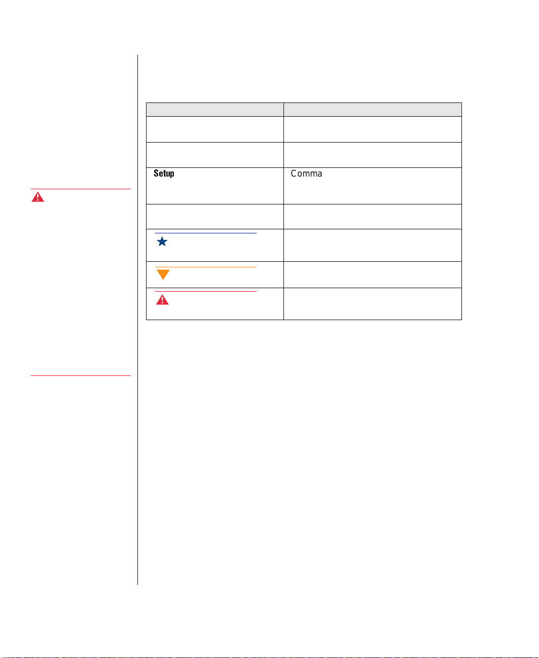
Con ventions used in this guide
Throughout this guide, you will see the follo wing con v entions:
Convention Description
NTER
E
TRL+ALT+DEL
C
Setup
User’s Guide
Important!
Caution!
Warning!
Keyboard key names are prin ted in small
capitals.
A plus sign indicates tha t the ke ys must be
pressed simultaneously.
Commands to be entered, options to
select, and messages that appear on your
monitor are printed in bold.
Names of publications and files are printed
in italic.
An important informs you of special circumstances.
A caution warns you of possible damage
to equipment or loss of data.
A warning indicates the possibility of personal injury.
Refer all servicing of those
compartments to qualified
service personnel.
Safety instructions
Observe the follo wing safety instructions w hen using y our system:
iv Gateway ALR 8300 User’s Guide
Foll ow all instructions marked on t he system and in the
•
documentation.
When the computer is turned off, a sma ll amount of electric al
•
current still runs through the computer . Al wa ys unplug the
computer from the electrical outl et before cleaning t he system or
opening the computer co ver. (Foll ow t he cleaning instructions in
your user’s guide.)
Do not use this product near wat er or a heat source, such a s a
•
radiator or heat registe r .
Do not spill anything on or into the system. The best wa y to a v oid
•
spills is to av oid eating and dr inking near y our system.
Make sure you set up the system on a stab le w ork surface.
•
Page 7

Openings in the computer cabinet are pro vided for ventilat ion. Do
•
not block or co ver these openings. Mak e sure you pro v ide adequate
space (at least 12 inches) ar ound the system for v entilation w hen
you set up y our w ork area. Ne ver insert object s of any kind into the
computer ventilation sl ots.
Use the voltage set ting for y our area. The v oltage sel ector swit ch is
•
set at the factory to the correct voltage.
As a safety feature, this syste m is equipped with a 3-wir e po w er
•
cord to ensure that the product i s properl y grounded when in use.
The plug will only fit into a grounding-type outlet. If you are
unable to insert the plug into a n outlet, contact an ele ctrician to
install the appropriate out let.
Do not walk on the po w er cord or allow anything to rest on it.
•
If you use an extensi on cord with this system, mak e sure the total
•
ampere ratings on the products plugged into the extens ion cord do
not exceed the extension cord ampere r ating. Also, the total ampere
requirements for all products pl ugged into the w all outlet must not
exceed 15 amperes.
There is a danger of explosion if the CMOS (complementary
•
metal-oxide semiconductor ) battery is replaced incorrectl y.
Replace the battery with the same or equiv alent type recommended
by the manufacturer . Dis pose of used batteries according to the
manufacturer’s instructions.
Unplug the system from the w all outlet and ref er servicing to
•
qualified personnel if:
• The pow er cord or plug i s damaged.
• Liquid has been spilled into the s ystem.
• The system does not operate properl y w hen the operating
instructions are follo w ed.
• The system was dropped or the cabinet is damaged.
• The system’s performance changes.
Preface v
Page 8

Additional inf ormation sources
Along with this manual and your us er’s guide, you can find additional
information by using the following sources.
The Gatewa y Support Center
Log on to the Gate wa y Support Center at www.gateway.com/support to
access information about your system or other Gate wa y products. Some
types of information you can access a re:
Hardware dri ver (including BIOS) a nd softw are
•
application updates
An expanded glossary
•
T ec hnical tips
•
Service Agreement information
•
T ec hnical documents and component info rmation
•
Frequentl y Asked Questions (FAQ)
•
Online access to Tech Support
•
vi Gateway ALR 8300 User’s Guide
Page 9

Chapter 1:
Getting Started
Before You begin..................................................... 2
Setting up the system............................................... 2
Starting the system................................................... 4
1
Page 10

Before You begin
Congratulations on your purchase. With the arriv al of your ne w system, you
are probabl y eager to assemb le the computer and ha ve it operat ing. This
section helps you:
Assemble the system
•
Connect the monitor and keybo ard
•
Start up the system
•
Carefully read and f ollo w these instructions to e nsure that yo ur system
operates correctly.
Setting up the system
Before you begin, y ou need to find and prepare the space the server wi ll
occupy.
Prepare a clean, flat, and firm surface for the server . Allo w at least
•
three inches at the rear of t he chassis for cab ling and air cir culation.
Protect the server from extreme temperatur e and humidity. Do not
•
expose the computer to direct sunl ight, heater ducts, and other
heat-generating objects.
2 Gateway ALR 8300 User’s Guide
Keep the system a w a y from equipment that generates magnetic
•
fields. Even a telephone placed too closely to the sys tem may
cause interference.
Protect the system against A C po w er s pikes b y using a 3-prong,
•
115-V or 230-V (depending on the voltage supplied in you r
locality) pow er cord, and an AC surge control po w er strip. The
system includes a TAC400 po w er suppl y. The pow er suppl y ships
with a single module and can support up to tw o modules. The
system requires a separate w all outlet f or each po w er suppl y
module. If both modules are instal led , the pow er supply provides
N+1 redundancy and hot-sw ap capabilit y.
Page 11
Inspecting the contents
Unpack the carton and inspect the contents. Standar d systems include th e
following items:
Server unit
•
Po w er cab les
•
User’s guide
•
Maintaining and troubleshooti ng guide
•
Utilities
•
Enhanced keyboard
•
Check the packing list to ensure t hat all equipment and associ ated manuals
are included in your sh ipment. Inspect e verything carefull y.
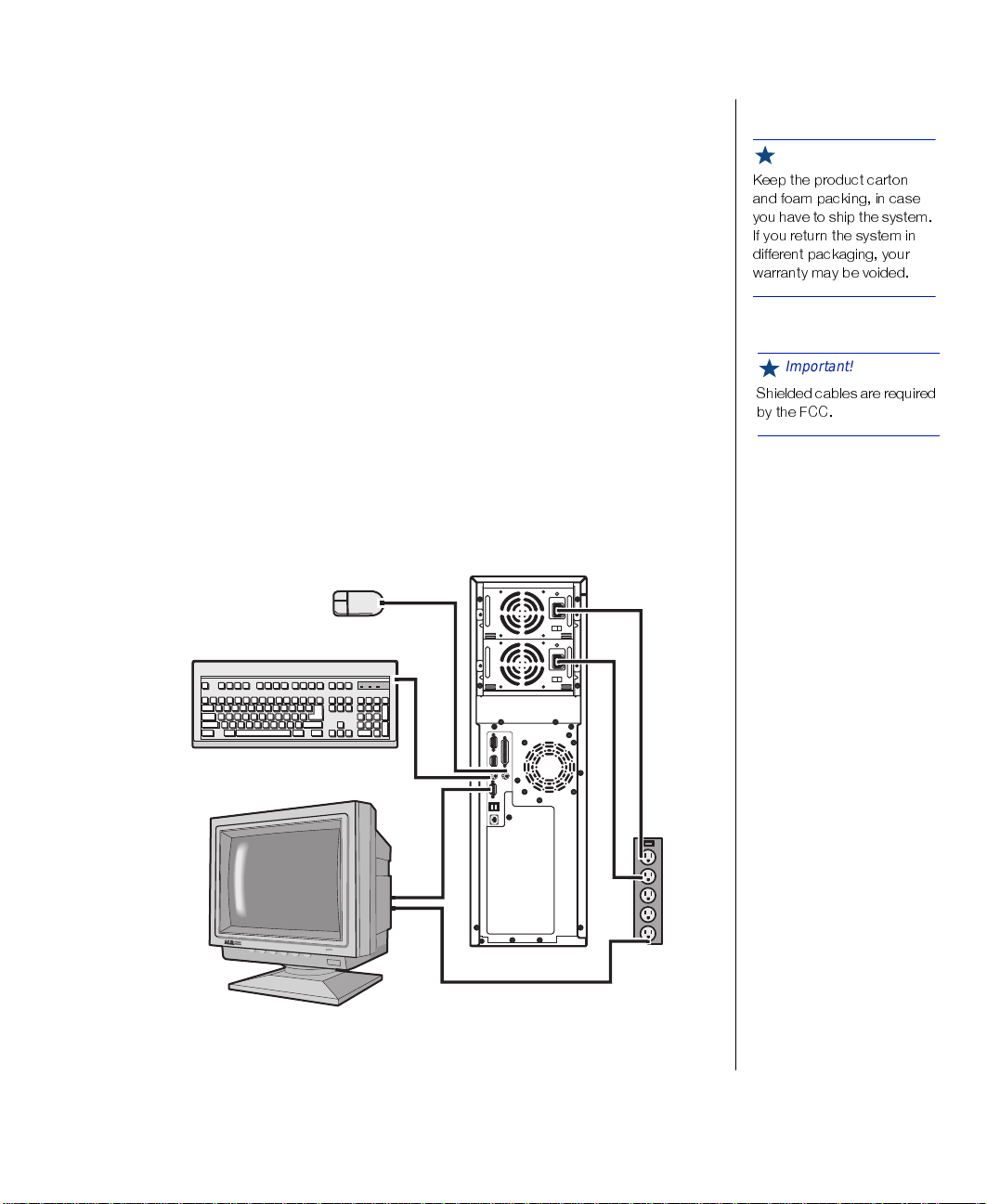
Setting up the server
Refer to Figure 1 and the following procedures w hen connecting optional
peripherals to your system.
Important!
/IIT XLI TVSHYGX GEVXSR
ERH JSEQ TEGOMRK MR GEWI
]SY LEZI XS WLMT XLI W]WXIQ
-J ]SY VIXYVR XLI W]WXIQ MR
HMJJIVIRX TEGOEKMRK ]SYV
[EVVERX] QE] FI ZSMHIH
Important!
7LMIPHIH GEFPIW EVI VIUYMVIH
F] XLI *''
Figur e 1: Connecti ng P er ipher als
Getting Started 3
Page 12

Caution!
When hot-swapping power
supply modules, always
unplug the module from the
wall outlet before
attempting to remove the
module.
To Connect Peripherals
Connect the keyboard (or ange) and mouse (purple) to their resp ectiv e
1.
ports using the pictures and color coding on t he back panel as a guide.
Connect the monitor video cab le (blue connec tor) to the matching b lue
2.
video port. The location of the port may v ary depending on whether
you use the inte grated video or a video card.
Connect the monitor po w er cable to an A C outlet or , pr eferabl y, a
3.
surge control outlet station.
Verify that the voltage s elector s witch on the po w er suppl y module is
4.
set for the proper vol tage (115V or 230V). If t he system includes tw o
pow er suppl y modules, each mod ule has a volt age selector s witch and
connects independentl y to the building po w er.
Connect the pow er cab le to t he AC -in po w er socket on t he po w er
5.
supply module. If the sys tem includes both modules, there is an A C-in
pow er socket on each module.
Connect the other end of the po w er cab le(s) to an A C out let.
6.
Starting the system
Warning!
For safety reasons, both
upper and lower bezel
doors must be closed and
locked while the system is
running.
4 Gateway ALR 8300 User’s Guide
Press the on/off s witch on the front pan el to start the system (see “Front
panel” on page 9 for the location of the po w er button). The green LED on
the front panel lights.
If you turn off th e system, you must w ait at l east ten seconds before you
turn the system back on.
The system self-checks the memory even i f the monitor is not connec ted. If
the monitor is connected and on, the scr een displa ys the start-up sequence,
including:
If more than one processor is inst alled , th e system displa ys whic h
•
processor it is currently testing .
Page 13
If any errors are encountered , t he system displa ys them on the
•
monitor.
If a monitor is not connected or th e system is unab le to displa y an
•
error, an error beep code sounds.
If the system encounters an error , it is most likel y a nonfatal one, meaning
the system will function until t he error is corrected (usually through t he
BIOS Setup). In the rare case of a fatal error, see “Quick check” on page5
below. If the information in this guide does not solve the prob lem, check
your
Maintaining and T r oubleshooting t he Gateway ALR 8300 Server
for
additional trouble shooting information.
Quick chec k
Important!
-J XLI '137 LEW FIIR
GSVVYTXIH F] E TS[IV
SYXEKI SV ER MRXIVVYTXIH
JPEWL YTHEXI ERH ]SY TPYK
XLI W]WXIQ MRXS E TS[IV
SYXPIX MX [MPP TS[IV YT
MQQIHMEXIP] 8LMW MW RSVQEP
Sometimes, the simplest things can cause troub le. To avoid unnecessary
service calls, be sure you check o v er the basi cs before you call for support.
If the system does not operate correctl y, re-read the instructions for the
procedure(s) you ha v e performed. If an error occurs within an application,
consult the documentation supplied with the software.
This section identifies solutions to common problems.
Looking things over
In any complex sy stem, there is potential for a forgotten c onnection, a
forgotten s witch, or a loose conne ctor . If y ou try to start up the server and it
does not start up, perform the follo wing checks:
Is each pow er cord connected to the server unit and an A C outlet?
•
Is the AC outlet suppl ying po w er?
•
If you use a po w er strip, i s it turned on? Is the circuit breaker set?
•
Does the voltage select ion switch on t he system po w er suppl y
•
module(s) reflect the proper v oltage?
Important!
% HIPE] MR ZMHIS QE] FI
GEYWIH F] PEVKI QIQSV]
GSRJMKYVEXMSR 3RGI XLI
FSSXYT WIUYIRGI LEW
GSQTPIXIH ]SYV HMWTPE] [MPP
VIXYVR
Getting Started 5
Page 14

V erifying your configuration
If your system is not operati ng correctly, the BIOS may contain an in valid
configuration parameter. Enter the BIOS pro gram and check your
configuration settings. The BIOS Setup utility , configuration fields, and the
options for those fields are described in the
the Gateway ALR 8300 Server
.
Maintaining and T r oublesho oting
Troubleshooting guidelines
As you troubleshoot t he system, keep the fol lo wing guidelines in mind:
Never remo v e the system co ve rs while the system is on.
•
Do not attempt to open the monitor . I t is extremel y dangerous.
•
Even if the monitor po w er is di sconnected , stored energ y in the
monitor components can cause a painful or h armful shock.
If a peripheral such as the k eyboard, mouse, drive, or pri nter does
•
not work, ensure that all connections are secure.
If the screen displa ys an error message, write it do wn
•
word-for -w ord. You may be asked about it wh en calling technical
support.
Only qualified personnel should open the system for maintenanc e.
•
6 Gateway ALR 8300 User’s Guide
If you are qualified to maintain the system your self, make certain
•
you are properl y grounded before opening the syste m chassis.
Page 15

2
Chapter 2:
System Features
Basic features........................................................... 8
Front panel............................................................... 9
Rear panel.............................................................. 12
Operating systems ................................................. 15
Page 16

Basic features
Intel Pentium® II Xeon™ processor (speed depends on the model)
•
SMP design supporting up to two proc essor modules
•
Intel MP Specification V1.1 and 1.4 compliant
•
32-bit PCI and 16-bit ISA bus master
•
64-bit processor and memory data path
•
Extended PCI-to-PCI bridge support
•
64-MB error checking and correcting (ECC) memory, e xpandabl e
•
to 2-GB using ECC PC100-compliant 100MHz 72-bit SDRAM
DIMMs
Integrated 2-MB DRAM PCI Graphics (Cirrus Logic GD54M30)
•
Seven e xpansion slots: five PCI, one shared PCI/RAIDport, and
•
one shared PCI/ISA
Integrated PCI Ultra2 SCSI (Adaptec 7890) with tw o 68-pin
•
connectors, dual-channel ultra-DMA PCI IDE interface, and
diskette controller supporting 1.44 MB and 2.88 MB formats.
RAIDport III ready: the shared PCI/RAIDport slot supports the
•
addition of a RAIDport card to pro vide RAID capabil ity.
8 Gateway ALR 8300 User’s Guide
Low vo ltage dif ferential (LVD) support for SCSI devices. LVD
•
SCSI allows faster disk access and greater data inte grity
Po w er suppl y unit that suppo rts dual 400 W redundant po w er
•
supply modules with hot s wap c apability. The system ships with a
single module. If you i nstall the optiona l second module, the po w er
supply supports load sharing and N+1 fault tol erance.
Phoenix upgradable Flash BIOS, Year 2000 Ready
•
The system is equipped with InforManager™ (IFM), a special
•
feature consisting of both hardw are and soft ware d esigned to
monitor and report the operating status of the syst em and its
devices: processors, power supplies, RAM, ambient temperature s,
voltages, and fan operation. For further information about the
InforManager
™
, refer to the InforManager
™
User’s Guide.
Page 17

Front panel
The front panel of the system is equipped wit h switches, LEDs, and dri ve
bays. See F igure 2 below.
Power button
Reset button
Keyboard lock b utton/ECC clear
Internal 3.5-inch drive bay
Power LED
Hard disk activity LED
3.5-inch
diskette
drive
Processor 1 activity LED
Processor 2 activity LED
ECC fault LED
Power supply f aul t LED
5.25-inch drive bays
Bezel doors
(open)
3.5-inch
LVD SCA
drive bays
Bezel key loc k
SCSI disk
activity LEDs
RAID bay backplane
(behind drive bays)
Figur e 2: Front Panel
System Features 9
Page 18

Buttons
The table belo w sho ws the f ront panel buttons and their functions. See
Figure 2 on page 9 for the locations of the buttons.
Switch Function
Power Turns the system on or off.
Reset Allows you to reset the system without powering
it off and then on again
Keyboard lock Enables or disables the keyboard functions and
clears the error flag after an ECC error. Pressing
this button does not corre ct the e rror c ond ition. If
you have not corrected the error condition, the
ECC fault LED will light again.
Internal 3.5-inch drive bay
The system includes an internal 3.5-inch dri ve ba y to acco mmodate a
3.5-inch IDE hard driv e or other 3.5-inch de vice that does not need to be
accessed from outside the system.
LED indicators
The table belo w sho ws the front pa nel indicator LEDs and their functions.
See Figure 2 on page 9 for the locations of the indicator LEDs.
LED Meaning When Lit
Power The system is on.
Hard disk controller
activity
P1 activity The first processor is active.
P2 activity The second processor is active.
ECC fault A memory error has been detected.
Power supply fault One of the power supplies has failed.
Hard disk activity (6) The corresponding LVD SCA drive is being
10 Gateway ALR 8300 User’s Guide
The hard disk is being accessed.
accessed.
Page 19

5.25-inch drive bays
The 5.25-inch driv e ba ys pro vide space f or up to five 5.25-inch de vices
such as CD-ROM dri ves, 5.25-inc h diskette dri ves, or tape dri ves.
Bezel doors and ke ylock
The top bezel door pro vides access t o the po w er , reset, and ke yboard inhibi t
switches, as w ell as t he 3.5-inch diskett e driv e and the 5.25-inc h driv e ba ys.
The low er bezel door pro vides access to the 3 .5-inch LVD SCA drive ba ys.
Both doors can be locked to pre vent una uthorized access.
RAID bay bac kplane
The RAID bay backplane supports connection of up to six 3.5-inch
hot-swappa ble, LVD SCA SCSI hard drives. The backpla ne automaticall y
sets SCSI ID numbers and pro vides termination. Settings allo w you to
divide the backplane into one or tw o channels .
3.5-Inch LVD SCA drive ba ys
The 3.5-inch LVD SCA drive bays all ow y ou to install up to six 1- or
1.6-inch hot-sw appable SCSI hard driv es. The drives use a guide rai l system
that allo ws easy installati on and remo v al. Cooling for the dri ve bays is
provided by internal fans.
Warning!
Both upper and lower bezel
doors must be closed and
locked while the system is
running.
3.5-inch diskette drive
The standard system is equipped with one half-height 1.44-MB 3.5-inch
diskette dri ve.
System Features 11
Page 20

Rear panel
l)
r
The rear panel of the system is equipped with I /O P orts, connectors, and
switches. See Fi gure 3 below.
Status light, power
supply 1 (PS1)
AC plug, PS1
Voltage selection
Power supply
module 2
(optional)
Parallel port
Serial port 1
switch, PS1
Status light, PS2
(optional)
AC plug, PS2
(optional)
Voltage selection
switch, PS2 (optiona
Serial port 2
Keyboard port
Dual USB ports
Ethernet port
Important!
8LI WIGSRHEV] 4'- WPSX
GSRRIGXSV QE] FI WLEVIH
[MXL XLI -
GSRRIGXSV
12 Gateway ALR 8300 User’s Guide
3 JIEXYVI
Secondary PCI
Video port
slots 1 & 2
covers
Chassis fan vent
Mouse port
Chassis key lock
Primary PCI sl ot
covers
Secondary PCI slot
4/ISA slot 1 cover
Secondary PCI slot
3/RAIDport slot cove
Figur e 3: Rea r Panel
Page 21

P ower supplies
The system supports two 400-Watt, redundant power suppl y modules
capable of load shari ng. The standard configuration includes a single
module. The second module can be purchased as an opti on and pro vides
redundancy (N+1 fault tolerance ) and hot-sw ap capabilit ies.
P ower supply status lights
Each pow er suppl y module has a multi-col or status light.
Green indicates normal operating mode
•
Amber indicates standby mode
•
No light indicates the po w er suppl y module is not re ceiving po w er
•
or has failed
V oltage selector switches
Located on the back of each po w er suppl y module, this s witch must be set
to the proper AC line voltage used in y our locality (115VAC or 230VAC). If
the optional second module is instal led , the re are tw o v oltage selector
switches.
Important!
8LI ZSPXEKI WIPIGXSV
W[MXGLIW EVI WIX EX XLI
JEGXSV] 'LERKMRK XLIQ QE]
VIWYPX MR WIZIVI HEQEKI XS
XLI WIVZIV
AC power-in connectors
This is a connector into the po we r supply t hat pro vides t he electrical current
to the system and peripherals. Using the po w er ca ble supplied with th e
system, connect the pow e r supply in to a wall out let. If the optional second
module is installed , there are tw o A C po w er -in connectors. If you use both
modules, plug each po wer ca ble into a se parate wal l outlet, preferab ly on
separate circuits.
System Features 13
Page 22

Fans
The exhaust fans pro vide airfl ow through the system to k eep the interior
temperature to acceptab le lev els. Do not b lock the v ents for these fans. I f a
fan stops working, r eplace it immediate ly. Excessive heat within the chassis
can damage other system components.
Important!
-J ]SYV QSYWI LEW E
QMRM(-2 GSRRIGXSV ]SY
QYWX GSRRIGX MX XS XLI
QSYWI TSVX
Chassis ke ylock
The chassis keylo ck allo ws you to s ecure the panels to t he chassis to pre vent
unauthorized access to the syste m and its peripherals.
Expansion slot cover plates
These are co ver plates f or their corresponding expansion s lots on the
system board. F or more information, see “Basic features” o n page 8 or
Maintaining and Tr oub leshooting the Gate way ALR 8300 Server
.
I/O ports
The following table sho ws the r ear panel I/O ports and their descript ions.
For t he locations of the ports refer to Figure3 on page 12.
Port Definition
Serial ports
1 and 2
These are high speed serial ports that use the
first-in-first-out (FIFO) protocol. If you have a serial
mouse, connect it to serial port 1 (COM1). Other serial
devices such as se rial printers or modems are also connected to these ports.
Parallel port Parallel devices such as parallel printers and scanners
Mouse port This port supports any mouse with a miniature circular
Keyboard
port
Video port Connects the monitor to the integrated video controller.
14 Gateway ALR 8300 User’s Guide
can be connected to this port.
DIN (mini-DIN) connector.
This port supports any keyboard with a miniature cir cular
DIN (mini-DIN) connector.
Page 23

Port Definition
Stacked
dual USB
ports
Integrated
LAN port
These ports support any USB compliant devices. USB
keyboards and mice may not be compatible with power
management functions.
This port supports an RJ45 connector to your LAN. The
LAN port has two small LEDs. These LEDs provide the
following information:
The green LED lights when the integrated
•
ethernet circuit detects a v alid link to the
network
The amber LED lights when the inte grated
•
ethernet circuit communicates at 100Mbps.
Otherwise it communicates at 10Mbps.
Operating systems
The system is 100% Intel MP Specification V1.1 or V1.4, BIOS-selectable
compliant. The follo wing operating syste ms support symmetrical
multi-processing (SMP):
Nov ell NetWare SMP 4.1 and 4.11
•
SCO UNIX 3.2.4.2
•
Important!
8LI 4IRXMYQ -- <ISR
TVSGIWWSV MR XLMW W]WXIQ MW
HIWMKRIH XS WYTTSVX FMX
STIVEXMRK W]WXIQW ERH
ETTPMGEXMSRW 8S IRWYVI
STXMQYQ W]WXIQ
TIVJSVQERGI YWI SRP]
FMX TVSKVEQW SR XLI
W]WXIQ
SCO UNIX ODT 3.0
•
SCO UNIX Open Server 5.X
•
UnixW are 2.01 and 2.1
•
Solaris® 2.1
•
IBM OS/2 SMP 3.0 Warp
•
Microsoft Windo ws NT™ Server 3.51 and 4.0
•
Microsoft Windo ws NT Workstation 3.51 and 4.0
•
Microsoft Windo ws NT Server 4.0 Ent erprise
•
Microsoft Small Business Server (SBS)
•
Important!
7'3 92-< ZIVWMSRW
ERH 3(8 VIUYMVI FSXL
14< < ERH %4-' (VMZIV
< XS WYTTSVX QSVI XLER
SRI TVSGIWWSV
System Features 15
Page 24

Because each operating system operates differ ently, it is best to reference
your operating system document ation for specific instructions on what to
do after the system boots.
The following operating systems run on the system but do not support the
system’s multiprocessing capabilities:
Microsoft Windo ws® 95
•
NeXTStep OS 3.3
•
Nov ell NetWare 3.1x and 4.x
•
If you are unsure w hether or not y our application or operating system
supports SMP, contact the product manufacturer .
16 Gateway ALR 8300 User’s Guide
Page 25

3
Chapter 3:
Maintaining and Cleaning Your System
Maintaining the system......................................... 18
Cleaning the system............................................... 22
Page 26

Maintaining the system
K
K
T
T
K
Maintaining the hard drive
Hard drives need r egular maintenance because running the sof tware di vides
files, creates spaces between data, and otherwise decreases the hard dri ve
performance. Windo ws 95 and W indo ws NT pro vide mainte nance tools
that help prevent hard dri ve prob lems. The tw o most important tools for
hard driv e maintenance are the pro grams ScanDisk and Disk Defragmenter .
(Windo ws NT does not incl ude Disk Defragmenter .)
Using ScanDisk
ScanDisk is a program that lets y ou check the hard disk for damaged areas
and then repair them. We suggest that you scan the hard dri ve at least once a
week to once a month, depend ing on ho w often and ho w much y ou use the
computer .
To Start ScanDisk
1.
In Windo ws 95, Click on the
then
%GGI
%GGIW
WWSVM
WSVMI
IW
W
, then
7
7]
]WX
WXIQ
button. Then click on
7X
7XE
EVX
VX
8SSPW
SSPW
, and then
IQ 8
7G
7GE
ER
R(
(MW
MWO
4
4V
O
,
V
VS
S
VE
EQW
QW
.
2.
3.
18 Gateway ALR 8300 User’s Guide
The ScanDisk window opens.
In Windo ws NT, Scandisk is accessed through the
drive
4
4V
VS
S
IV
IVX
XMI
MIW
sheet.
W
8
8SSPW
SSPW
tab of the
In the ScanDisk windo w, click on the driv e you w ant to scan.
If you onl y want to chec k the files and folders for errors, select the
7
7X
XE
ER
errors, select the
option button. If you want to do a more thorough scan for
RH
HE
EV
VH
H
VS
SY
YKL
option.
L
8
8L
LS
SV
Because the thorough option takes more t ime than the standard option,
we recommend y ou normally use the standar d option and do a
thorough check at least once a month.
Page 27

If you selected
K
K
]
4.
7
7X
XER
ERH
ScanDisk uses when i t checks files and folders, click on the
and you w ant to change the setti ngs
HEVH
EVH
%
%H
button, select the options in the ScanDisk Adv anced Options windo w,
then click on the
button to close the windo w.
3/
3/
or
HZE
ZER
RGI
GIH
H
If you selected
8
8L
LS
SV
uses when it checks the di sk surface, click on the
and want to change the sett ings ScanDisk
VS
SY
Y
L
L
3
3TX
TXMSR
MSRW
button,
W
select the options from the Surface Scan Options wi ndow, then click
on the
If you wa nt ScanDisk to automatic ally fix any errors it finds, select the
5.
%
%YX
YXSQE
Click on the
6.
button to close the windo w.
3/
3/
SQEX
XMGEPP
MGEPP]J
JM
M\ I
\IV
VV
VS
SV
VW
W
button in the ScanDisk window.
7
7X
XEV
EVX
X
option in the ScanDi sk windo w.
When the scan is complete, the ScanDisk Results wi ndo w opens
giving you details of the scanni ng operation.
If you want t o scan another dri ve, click on the
7.
button to return to
'PSWI
'PSWI
the ScanDisk windo w, select another driv e, then go to Step 6.
When you are finished using ScanDisk, click on the
8.
'
'PS
PSW
button.
WI
I
Using Disk Defragmenter
Windo ws NT does not include Disk Defragmenter.
The Disk Defragmenter pro gram helps maintain the i ntegrity of the hard
drive b y rearranging files so that unused space on the dri ve is not scat tered
around the driv e, but is contained in one c ontiguous area on the disk.
You may notice, after running Disk Defragmenter , that t he programs run a
little faster and more ef ficiently . Tha t is because the ha rd driv e head can go
directly to t he data it needs inst ead of skipping around t o differ ent places on
the disk to find pieces of data.
Maintaining and Cleaning Your System 19
Page 28

We suggest that you run Disk Defragmenter at least once a w eek to once a
K
K
K
month, depending on how much y ou use the system.
To Run Disk Defragmenter
Click on the
1.
and then
7]W
7]WX
button, then select
7
7X
XEV
EVX
X
XIQ
IQ 8
. Then select
8 SSP
SSPW
W
4
4VSKVE
VS
(
(MW
MWO
O (IJVE
VEQ
QW
(IJVE
, then
W
QIR
QIRX
%GGIW
%GGIWW
.
XI
IV
V
WSVMI
SVMIW
,
W
A dialog box opens asking y ou to select a dri ve t o defragment.
Select the driv e that you w ant to defragment from the pull-do wn
2.
menu, then click
3/
3/
.
A dialog box o pens sho wing the pro gress of the defragmentation.
When defragmentation is complete, a dia log bo x opens and asks you i f
you want to qu it the Disk Defragmenter pro gram.
If you are finished defragmenting the drives i n your system, cl ick
3.
If you hav e more dri ves to defr agment, click
and return to Step 2.
2S
2S
=
=I
IW
Computer Virus notice
A virus is a program written with maliciou s intent for the sole purpose of
creating hav oc in a comput er system. It attaches i tself to ex ecutab le files or
boot sectors, so it can replicate an d spread. Some viruses may onl y cause
the system to beep or displa y messages o r images on the screen. Other
viruses are highly destructi ve and corrupt or erase the contents of files or
disks. T o be safe , nev er assume an y virus is harmless.
.
W
Viruses are identified by ho w they infect the computer .
•
•
•
20 Gateway ALR 8300 User’s Guide
Program Viruses
infect ex ecutable pro gram files such as.COM,
.EXE, .O VL, .DRV, .SYS, and .BIN.
Macro Viruses
infect the data files of specific programs. These
viruses are written in the macro languages certain appl ications use
to enhance their functionalit y. These viruses do not infect other
programs or the boot sector.
Boot Viruses
attach themselves to a Boo t Record , Master Boot,
FAT , or P artition Table.
Page 29

•
Multipartite Viruses
Viruses are inacti ve u ntil the infec ted program is e xe cuted , or a boot r ecord
is read. Thereafter , the virus loads itsel f into system memory and begins to
copy and spread it self. Disket tes used in a contaminated s ystem can get
infected and , in turn, transfer the virus w hen used in another syste m. A
virus can also spread via programs do wnloaded f rom bulletin boards or the
Internet.
are both program and boot infectors.
To Prevent Virus Infection
Obtain an anti-virus program and make i t a habit to scan the
•
system regularl y.
Make backup copies of all files and write-protect the disks.
•
Obtain all softwar e from reputab le sources and al w a ys scan ne w
•
software for an y viruses prior to inst alling files.
If you suspect the system has bee n infected , find and remov e the viruses
immediately using an ant i-virus program. Then turn off th e system for a
minimum of 15 seconds to clear the virus from system RAM. You may
want to rerun the anti-virus softw are w hen you turn the sy stem back on the
verify that the syst em is clean.
Maintaining and Cleaning Your System 21
Page 30

Cleaning the system
Your system and its components need to be cleaned occasionall y. Some
programs that help maintain the inte grity of the hard dri ves in the syst em
come as part of the Windo ws 95 and W indo ws NT opera ting systems. The
following s ections contain information about cl eaning the v arious e xternal
parts of the system.
Cleaning the mouse
If the mouse pointer on the screen mo ve s erratically w hen you mo v e the
mouse, dirt is probably on the r ollers inside the mouse .
To Clean the Mouse
1.
Shut down the system.
2.
T urn the mouse upside do wn and remove the mouse ball cov er .
3.
Cup your hand under the mouse, then tu rn the mouse right-side up.
The gray mouse-ball should drop into y our hand. If it doesn’ t, gentl y
shake the mouse until the ball drops out of the soc ket.
4.
5.
Cleaning the keyboard
Occasionally y ou should clean the k eyboard to free it of dust and l int
particles trapped under the ke ys. The easiest w a y to do this is to blo w
trapped dirt from under the keys using an aerosol can of ai r with a narrow,
straw-li ke extensi on.
22 Gateway ALR 8300 User’s Guide
Once the mouse ball is free, use adhesi ve tape to pick up any dus t or
lint on its surface and wipe a w a y dirt or lint inside the mouse- ball
socket. You can also blow into the socket t o remo ve dirt and lint . If
foreign matter is trapped insi de the socket or on t he rollers, use a
cotton swa b dipped in isoprop yl alcohol to loosen i t. Allo w surfaces to
dry completely after cleanin g.
Return the mouse ball to the socket and repl ace the co v er , then restart
the system.
Page 31

If you spill liquid on the keyboard, shut down the computer an d disconnect
the keyboard. Turn the keyboard upside do wn to allo w the liquid to drain
out ov ernight before trying to use it agai n. If it fails to w ork a fter draining,
contact technical support.
Cleaning the monitor screen
Use a soft cloth and windo w cleaner to clean the monitor screen. Squirt a
little cleaner on the cloth (ne v er directl y on the screen), an d wipe the screen
with the cloth.
Cleaning the computer and monitor cases
Alw ays sh ut do wn the system and other periphe rals before cleaning any
components.
Use a damp, lint-free cloth to clean the computer case, monit or case,
keyboard , spea kers, and other parts of you r system. Avoid abrasive or
solvent cleaners becaus e they can damage the finish on your components.
Maintaining and Cleaning Your System 23
Page 32

24 Gateway ALR 8300 User’s Guide
Page 33

Appendix
Acronyms and abbreviations................................. 26
Terms and definitions............................................ 30
Regulatory compliance statements....................... 35
A
Page 34

Acron yms and abbreviations
AC - Alternating current
ACPI - Advanced Configuration & Po w er Interface
APIC - Advanced programmab le interrupt controller
ASCII - American standard code for information interchange
ASIC - Application specific integrated circuit
ATAPI - AT advanced peripheral interface
BIOS - Basic input/output system
BIST - Basic integrity self-test
CD - Compact disc
CD-ROM - Compact disc, re ad-only memory
CHS - Cylinder, head, sector
CMOS - Complementary metal-oxide semiconductor
CPU - Central processing unit
DBE - Double bit errors
DIMM - Dual inline memory module
DMA - Direct memory access
DMI - Desktop management interface
DRAM - Dynamic random access memory
ECC - Error correcting code
ECP - Enhanced capabilities port
EDO - Extended data output
EMC - Electro-magnetic compatibility
EMI - Electro-magnetic interference
26 Gateway ALR 8300 User’s Guide
Page 35

EPP - Expanded parallel port
ESD - Electro-static dischar ge
FAT - File allocation table
GB - Gigabyte
IDE - Integrated driv e electronics
I/O - Input/output
IRQ - Interrupt request line
ISA - Industry standard architecture
KB - Kilobyte
LAN - Local area network
LBA - Logic al block addressing
LED - Light-emitting diode
LVD - Low volt age diff erential
MB - Megabyte
MBE - Multiple bit error
Mbps - Megabits per second
MIDI - Musical instrument digital interface
MHz - Megahertz
MS-DOS - Microsoft disk operating system
NMI - Non-maskable interrupt
NTFS - NT file system
NVRAM - Non-volatile random-access memory
OS - Operating system
PCI - Peripheral component int erconnect
Appendix 27
Page 36

PIC - Programmable interrupt controller
PIO - Paged input/output
PnP - Plug and play
POST - Po wer -on self-t est
PS/2 - Personal System/2
RAID - Redundant array of inexpensi ve dri ves
RAM - Random-access memory
RMA - Return material authorization
ROM - Read-only memory
rpm - Revolutions per minute
RTC - Real-time clock
SBE - Single bit error
SCA - Single connector attachment
SCI - Signal control interrupt
SCSI - Small computer system interface
SDRAM - Synchronous dynamic random access memory
SE - Single-ended
SEC - Single edge contact
SMI - System management interrupt
SMM - Server management module
SMP - Symmetrical multiple proces sor
SV GA - Super video graphics array
TCP/IP - Transmission control protocol/Internet protocol
UPS - Uninterruptable pow er suppl y
28 Gateway ALR 8300 User’s Guide
Page 37

USB - Universal seria l bus
V - Volt
VAC - V olts al ternating current
VGA - Video graphics array
VRM - Voltage regulator module
W - W att
Appendix 29
Page 38

T erms and definitions
This list of terms should help you get acquainted with t erms used in your
computer’s documentation and in your system softw are.
Applications - Softw are installed on y our system. Sometimes cal led
pro gr ams.
BIOS - Basic input/output system. The BIOS is softw are that is
independent of any operati ng system. It enabl es the computer to
communicate with the monitor , keyb oard , and other per ipheral de vices
without using programs on the ha rd disk.
The BIOS on your computer is flash BIOS, w hich means that is has been
recorded on a memory chip that can be updated if needed.
Boot - T o load the first software program (usuall y the operat ing system)
that starts your computer . To perform a cold (or hard) boot, you turn the
computer on when it is of f. To perform a warm (or soft) boot, you reset the
computer when it is a lready turned on.
Boot disk - A disk containing operating s ystem programs requi red to start
your computer . A boot disk can be a diskette, ha rd driv e, or CD .
Byte - The basic unit of measure for computer memory. A character, s uch
as a letter of the alphabet, uses one b yte of memory. Each byte is made up
of eight bits. Computer memory is often measured in kilob ytes (1,024
bytes) or meg abytes (1,048,576 b ytes).
Cache memory - Cache is very fast memory that can be located in the
processor . Cache reduces the average time required for the proce ssor to get
the data it needs from the main memory by storing r ecently accessed dat a in
the cache.
CMOS memory - Complementary metal oxide semiconductor memory.
CMOS memory is memory that is retained even when the compute r is
turned off. The Setup pro gram settings and other parameters are maintained
in CMOS memory.
Default - The option that the soft ware or syst em uses when y ou ha ve not
made a choice yourself.
Disc - A compact disc (CD).
30 Gateway ALR 8300 User’s Guide
Page 39

Disk - The device used by t he computer to store and re triev e information.
Disk can refer to a diskett e or a hard disk.
Diskette - A removab le disk, also called a flopp y.
Hard drive - The dri ve instal led inside y our computer that stores a ll your
system and data files. Depending on its configuration, the computer ma y
have more than one hard driv e. Each dri ve is assigned its o wn dri ve lett er . If
you ha ve onl y one dri ve, its dr iv e letter is C, an d it is often called “the C
drive.”
I/O - Input/output. Refers to de vices, such as printers, w hose purpose is to
enter data into a computer or e xtract data from a computer. An I/O device is
accessed through an I/O address: a l ocation in memory reserved for the
device to e xchange information betw een itself a nd the rest of the com puter .
IRQ - Interrupt request line. The IRQ is a hardware line that a de vice uses
to signal the processor w hen the de vice needs the proce ssor’s services. The
number of IRQs is limited b y industry standards.
Operating system - A program that supervises the computer’s operation,
including handling I/O , netw orking and connectivi ty, and device dri vers.
Path - A sequence of information that directs the syst em to the file it needs.
For e xample, c:\windows\bubbles.bmp is the path to a graphics file on
your system. The c: tells the system it is on the C hard dri ve, the \windo ws
tells the system it is in th e windo ws folder , and bubbles.bmp is the file.
Pixel - A pix el is an indi vidual dot in a graphic displa y ed on y our computer .
Pixels are so cl ose toget her that they l ook as though they are connected.
POST - Pow er -on self-test . POST tests you r computer’s components
whenev er you turn on the computer .
Programs - Softw are installed on y our system. Pro grams are sometimes
called applications.
RAM - Random access memory . RAM is the computer’s system memory .
You can write to and read from RAM. Information stored in RAM is
temporary and is erased when the c omputer is turned off.
Appendix 31
Page 40

Refresh rate - The refresh rate is the rate at w hich the image on the monit or
screen is rewrit ten to the screen. A fast ref resh rate helps ke ep the image
from flickering.
Resolution - The resolution is the sharpness or clarity of the image on the
monitor screen. Resolution is measured b y the number of pixe ls the screen
can display. For example, a resolution of 800x600 means that t he screen can
display 800 pix els in a ro w and can displa y 600 ro ws. The more pix els
display ed , t he higher the resoluti on and the clearer the i mages.
ROM - Read-only memory. P ermanent computer memory dedicated to a
particular function. F or example, t he instructions for starting the compu ter
when you first turn on pow er are contai ned in R OM. You cannot write to
ROM.
32 Gateway ALR 8300 User’s Guide
Page 41

Appendix 33
Page 42

American Users
Caution!
The Federal
Communications
Commission warns users
that changes or
modifications to the unit not
expressly approved b y the
party responsible for
compliance could void the
user’s authority to operate
the equipment.
Regulatory compliance statements
FCC notice
This device has been tested and found to comply with the limits for a Class A
digital device, pursuant to Part 15 of the FCC rules. These limits are designed to
provide reasonable protection against harmful interference in a residential
installation. This equipment generates, uses, and can radiate radio frequency
energy and , if not installed and used in accordance with the instructions, may cause
harmful interference to radio or television reception. How eve r, there is no
guarantee that interference will not occur in a particular installation. If this
equipment does cause interference to radio and televi sion reception, w hich can be
determined by turning the equipment off and on, the user is encouraged to try to
correct the interference by one or more of the following measures:
Reorient or relocate the receiving antenna
•
Increase the separation between the equipment and receiver
•
Connect the equipment into an outlet on a circuit different from that to
•
which the receiver is connected
Consult the dealer or an experienced radio/TV technician for help
•
This equipment has been tested and found to comply with the limits of a Class A
digital device. The accessories associated with this equipment are as follows:
Shielded video cable
•
Shielded pow er co rd
•
These accessories are required to be used in order to ensure compliance with FCC
rule s .
34 Gateway ALR 8300 User’s Guide
Page 43

Industry Canada notice
This digital apparatus does not exceed the Class A limits for radio noise emissions
from digital apparatus as set out in the radio interference regulations of Industry
Canada.
Le présent appareil numérique n’émet pas de bruits radioélectriques dépassant les
limites applicables aux appareils numériques de Classe A prescrites dans le
règlement sur le brouillage radioélectrique édicté par Industrie Canada.
Attention!
Couper le courant avant l’entretien.
CE notice
Canadian Users:
This Information T echnolo gy Equipment has been tested and found to compl y with
the following European directi ves:
[i]EMC Directive 89/336/EEC amending directi ve 92/31/EEC & 93/68/EEC as per
-EN 50081-1:1992 according to
EN 55022:1995 Class A
EN 61000-3-2:1995 or EN 60555-2:1986
EN 61000-3-3: 1995
-EN50082-1:1992 according to
EN 61000-4-2:1995 or IEC 801-2:1984
ENV 50140:1994 or IEC 801-3:1984
EN 61000-4-4:1988 or IEC 801-4:1998
[ii]Low Voltage Directive (Safety) 73/23/EEC as per EN 60950: 1992
European Users:
Appendix 35
Page 44

Japanese Users:
Australian and New
Zealand Users:
VCCI notice
This is a Class A product based on the standard of the V olunt ary Control Council
for Interference by Information T echnolog y Equipment (VCCI). If this equipment
is used in a domestic environment, radio disturbance may arise. When such trouble
occurs, the user may be required to take corrective action.
Australia/Ne w Zealand notice
This device has been tested and found to comply with the limits for a Class A
digital device, pursuant to the Australian/New Zealand standard AS/NZS 3548 set
out by the Spectrum Management Agency.
Caution!
Disconnect power before servicing.
36 Gateway ALR 8300 User’s Guide
Page 45

Index
Numerics
3.5-inch
diskette drive 11
internal drive bay 10
LVD SCA drives 11
5.25-inch devices 11
A
abbreviations 26
AC power, power supply 2
AC-in connector
connecting 4
power supply 13
activity indicators 10
CPU 10
LVD SCA SCSI 10
power supply modules 13
processor 10
Adaptec 7895 8
Australia/New Zealand Notice 36
B
backplane, RAID 11
BIOS
correctable errors 5
MP version selection 15
year 2000 ready 8
button
ECC clear 10
keyboard lock 10
on/off 10
power 10
reset 10
C
case, cleaning 23
CE Notice 35
chassis fan 14
chassis keylock 14
Cirrus Logic video chip 8
cleaning
computer case 23
hard drive 18
keyboard 22
monitor case 23
monitor screen 23
mouse 22
configuration, verifying 6
connecting
AC power 4
keyboard 4
monitor 4
mouse 4, 14
peripherals 3
serial mouse 14
video 4
controller
diskette 8
IDE 8
ultraSCSI 8
correcting BIOS configuration
errors 5
CPU
activity indicators 10
InforManager 8
operating systems supported 15
testing 4
D
definitions of terms 30
DIMM, supported 8
Disk Defragmenter, using 19
disk drive
3.5-inch diskette 11
5.25-inch 11
Index 37
Page 46

diskette controller 8
IDE controller 8
LVD SCA activity indicators 10
LVD SCA, 3.5-inch 11
ultraSCSI controller 8
diskette
3.5-inch 11
controller 8
DRAM, video 8
drive bay, SCSI SCA LVD 11
E
ECC
clear button 10
memory 8
error checking and correcting
see ECC
error messages 5
errors, troubleshooting 6
expansion slots
ISA 8
PCI 8
PCI/ISA 8
PCI/RAIDport 8
shared 8
F
fans, chassis 14
FAQ, accessing vi
FCC Notice 34
features
front panel 9
rear panel 12
system 8
flash BIOS 8
front panel
features 9
illustration 9
G
glossary, accessing on Internet vi
graphics
DRAM 8
memory 8
PCI 8
guidelines for troubleshooting 6
H
hard drive
internal 3.5-inch bay 10
maintaining 18
RAID bay 11
SCA LVD SCSI bay 11
hot-swap
power supply modules 8, 13
SCSI drives 8, 11
I
IDE controller, ultra DMA 8
indicators
CPU activity 10
LVD SCA SCSI drive
activity 10
power supply module failure 10
power supply modules 13
processor activity 10
Industry Canada Notice 35
InforManager™ 8
CPU 8
power supply 8
processor 8
Intel MP specification, sele cting 15
ISA, expansion slots 8
K
keyboard
cleaning 22
connecting 4
lock button 10
keylock, chassis 14
38 Gateway ALR 8300 User’s Guide
Page 47

L
LED indicators 10
lights, indicator 10
low voltage differential
activity indicators 10
drives 11
SCSI 8
LVD
see low voltage differential
M
maintaining, hard drive 18
manual conventions iv
memory
ECC 8
standard 8
supported 8
monitor
cleaning 23
connecting 4
mouse
cleaning 22
connecting 4, 14
serial, connecting 14
MP specification, selecting 15
multiprocessing
supported OSs 15
when not supported 16
N
NeXTStep, versions supported 16
Novell NetWare, versions
supported 15
O
on/off button 10
operating systems
multiprocessing 15
NeXTStep 16
non-multiprocessing 16
Novell NetWare 15
OS/2 15
SCO UNIX 15
small business server 15
Solaris 15
supported 15
UnixWare 15
Windows 95 16
Windows NT 15
OS/2, versions supported 15
P
PCI
expansion slots 8
graphics 8
PCI/ISA, expansion slot 8
PCI/RAIDport, expansion slot 8
peripherals, connecting 3
power supply
AC-in connector 4, 13
characteristics 2
hot-swap modules 8, 13
InforManager 8
module failure indicator 10
status lights 13
voltage selector switch 4, 13
power switch 10
powering up the system 4
power-on self-test 4
processor
activity indicators 10
InforManager 8
operating systems supported 15
supported 8
testing 4
R
RAID, backplane 11
RAM
ECC 8
Index 39
Page 48

supported 8
rear panel
features 12
illustration 12
regulatory compliance statements 34
reset button 10
S
safety guidelines iv
safety, closing the bezel doors 4
SCA
see single connector attachment
ScanDisk, using 18
SCO UNIX, versions supported 15
SCSI
activity indicators 10
controller 8
self-checks on power up 4
shared expansion slots 8
single connector attachment
drives 11
hot-swap drives 8
Small Business Server, versions
supported 15
Solaris, versions supported 15
status lights
front panel 10
power supply modules 13
system 10
support options 5
supported
DIMMs 8
memory 8
RAM 8
switch
ECC clear 10
keyboard lock 10
on/off 10
power 10
reset 10
system
errors 5
features 8
management 8
monitoring 8
power 4
self-checks 4
status lights 10
T
testing
CPU 4
processor 4
troubleshooting guidelines 6
turning on the power 4
U
ultraSCSI, controller 8
UnixWare, versions supported 15
using
Disk Defragmenter 19
ScanDisk 18
V
VCCI Notice 36
verifying your configuration 6
video
chip manufacturer 8
connecting 4
DRAM 8
voltage requirements, power
supply 2
voltage selector switch
location 13
setting 4
W
warning, closing the bezel doors 4
Windows 95, supported versions 16
Windows NT, supported versions 15
40 Gateway ALR 8300 User’s Guide
 Loading...