


 Loading...
2008®T
HEMODIALYSIS SYSTEM
TECHNICIAN’S
MANUAL
Part Number 490130 Rev. H
Fresenius Medical Care North America
920 Winter St.
Waltham, MA 02451
Manufactured by: Fresenius USA, Inc. 4040 Nelson Avenue Concord, CA 94520
http://www.fmcna.com
Copyright 2008 – 2017 Fresenius Medical Care, All Rights Reserved
2008T Technician’s Manual
© Copyright 2008 – 2017 Fresenius Medical Care, All Rights Reserved
This document contains proprietary and confidential information of Fresenius USA, Inc. d/b/a Fresenius Medical Care North America and its affiliates (“Fresenius Medical Care”). The contents of this document may not be disclosed to third parties, copied, or duplicated in any form, in whole or in part, without the prior written permission of Fresenius Medical Care.
Fresenius Medical Care, the triangle logo, 2008, Diasafe and bibag are trademarks of Fresenius Medical Care Holdings, Inc., or its affiliated companies. All other trademarks are the property of their respective owners.
Any questions, contact Technical Support at 800-227-2572

TABLE OF CONTENTS
I SPECIFICATIONS
II HYDRAULIC DESCRIPTION
III ELECTRONIC CIRCUIT DESCRIPTION
IV MODULE DESCRIPTION
ADDITIONAL DOCUMENTATION*:
2008T OPERATOR’S MANUAL (P/N 490122)
2008T CALIBRATION PROCEDURES (P/N 508032)
2008T PREVENTIVE MAINTENANCE PROCEDURES BOOKLET (P/N 508033)
2008T HYDRAULIC FLOW DIAGRAMS (P/N 700078)
2008T ELECTRONIC BLOCK DIAGRAMS (P/N 290443)
2008T DEBUG SCREENS BOOKLET (P/N 490139)
2008T OPTIONS CONFIGURATOR INSTRUCTIONS (P/N 508635) bibag® V2.0 TECHNICIAN’S MANUAL (P/N 490188)
* The latest revision of the additional documentation can be found at the following web location:
https://fmcna.com/product-support-documentation/
2008T Technician’s Manual – 490130 Rev. H |
i |
Section I – Specifications
SECTION I - SPECIFICATIONS
2008T HEMODIALYSIS MACHINE
Refer to the “Machine Specifications” section of the 2008T Operator’s Manual (P/N 490122)* for the complete list of machine specifications for the 2008T Hemodialysis machine.
Conventions
Symbol |
Description |
|
Warning! A statement that identifies conditions or actions that could |
and |
result in personal injury or loss of life. Warnings found in this manual |
outside of this section are designated with the warning symbol. |
|
|
Note: Notes are advisory comments or recommendations regarding |
|
practices or procedures. |
|
|
* The latest revision of documentation can be found at the following web location:
https://fmcna.com/product-support-documentation/
2008T Technician’s Manual – 490130 Rev. H |
I-1 |

Section I – Specifications
PRODUCT IMPROVEMENT POLICY
The 2008T Hemodialysis machine was designed and built to comply with the product specifications outlined in the 2008T Operator’s Manual (P/N 490122). It is the intention of Fresenius Medical Care North America to improve products continuously, a process which may result in modifications to specifications or equipment produced in the future. Such product improvements shall not incur any obligation to make similar changes or improvements to equipment previously produced. These changes or improvements may or may not be applicable or usable with previously produced equipment. Where possible, improvements will be made available at reasonable prices. Any such improvements shall not be construed as corrections of any perceived deficiency.
In order to properly calibrate and maintain the 2008T Hemodialysis machine, the documentation being used must be up to date. The current revision of a document can be obtained from the Fresenius Medical Care Website at:
https://fmcna.com/product-support-documentation/
2008T Technician’s Manual – 490130 Rev. H |
I-2 |

Section II – Hydraulic Description
SECTION II – HYDRAULIC DESCRIPTION
DESCRIPTION OF THE HYDRAULIC COMPONENTS
All valves and motors are supplied with 24V DC; the heater is supplied with 120V AC 60Hz; thermistors, float switch, blood leak detector, pressure sensors and reed switches with 12V DC; conductivity cell and level sensor with 12V AC at high frequencies;
Inlet filter screen
Prevents the 2008T Hemodialysis machine components from being obstructed (mounted in the inlet water line).
Water inlet regulator
Limits the inlet water pressure.
Balancing chamber
The most important component for volumetric dialysate balancing; two spherical chambers (30m1 each); 8 solenoid valves; two membranes reliable and proven hydraulic component from A2008C/D/E/H series; guarantees accurate fluid balancing.
Hydrochamber
Consists of a heater including valve “39” and an orifice to provide sufficient volume to deaerate the water; separates the air from the water and provides mounting for the loading pressure valve; control NTC 2 (temperature sensor for temperature control circuit);
Function: warming water; provides air gap and a level sensor to maintain the water level.
Monitoring NTC 3
Function: independent temperature sensor for temperature monitoring.
Flow indicator
Optical flow indication and gross flow measurement.
Dialyzer valves V24, V25, and bypass valve V26
Bypasses (V24 closed, V25 and V26 open) the dialyzer and prevents exposure of the patient to improper dialyzing fluid (temperature or conductivity alarm); the dialyzer can be isolated (V24 and V25 closed, V26 open; i.e. for online pressure holding test or resetting a hardware TMP alarm (i.e. adjusting TMP). For adjusting TMP, V24 closed, V25 and V26 open to serve as bypass.
Dialysate line safety interlock 2 switches for dialysate lines;
1 switch for bypass when shunt cover is open;
provides additional safety against inadvertently rinsing or disinfection; defines dialyzer emptying program.
Dialyzer filter
Prevents hydraulic components from being obstructed; mounted outside 2008T Hemodialysis machine; easy to service.
2008T Technician’s Manual – 490130 Rev. H |
II-1 |

Section II – Hydraulic Description
Dialysate pressure transducer
Pressure transducer for dialysate pressure measurement; used as a sensor for the pressure holding test. It is also used to switch the balancing chamber in rinse mode.
Blood leak detector
Color sensitive blood leak detector (temperature compensated), is able to distinguish between opaque layers in the cell and real presence of blood in the dialyzing fluid.
Secondary air separation
Prevents air from entering the balancing chamber assuring precise weight removal; device contains fluid level detector, air separation volume and valve V43.
Mixing chamber(s)
A cylindrical chamber that swirls the proportioned dialysate solution which provides for a complete mixing prior to entering the balancing chamber.
Chamber Full Switch
Pressure transducer that senses pressure peak to switch the balance chamber.
Flow pump
DC motor driven gear pump;
Function: filling of the balancing chamber, spent side.
Deaeration pump
Provides deaeration and loading pressure.
Heat exchanger
Preheats inlet water by using the thermal energy in the spent dialysate.
Conductivity cells
Measures conductivity pre dialyzer. There are two conductivity cells, one pre dialyzer and one post dialyzer.
UF pump
Responsible for fluid removal
Acid pump
Delivers acid proportioned by the microprocessor according to settings in the Dialysate Composition Screen.
Bicarbonate pump
Delivers bicarbonate proportioned by the microprocessor according to settings in the Dialysate Composition Screen.
Recirculation valve V29
Allows fluid to the drain to be diverted into the hydrochamber; used in heat disinfect to heat up faster and to conserve energy.
2008T Technician’s Manual – 490130 Rev. H |
II-2 |

Section II – Hydraulic Description
HYDRAULIC CONNECTION PANEL
TO DIALYZER - tubing to dialyzer (blue dialyzer quick connector)
FROM DIALYZER - tubing from dialyzer (red dialyzer quick connector)
WATER INLET - hose for water inlet
TO DRAIN - outlet hose to drain
GROUND - fixing screw for potential equalization
2008T Technician’s Manual – 490130 Rev. H |
II-3 |
Section II – Hydraulic Description
HYDRAULIC OPERATION
1. Time constants
The overlap time (delay time) of the balancing chamber valves is always 50 ms. This time is included in the switching time of the balance chamber (i.e., switching time is 6.00 seconds means a 5.95 second fill time plus a 50 ms delay time).
Time constants of the balance chamber.
Flow rate 100 ml/min t = 18.0 s ± 10%
Flow rate 200 ml/min t = 9.0 s ± 10%
Flow rate 300 ml/min t = 6.0 s ± 10%
Flow rate 400 ml/min t = 4.5 s ± 10%
Flow rate 500 ml/min t = 3.6 s ± 10%
Flow rate 600 ml/min t = 3.0 s ± 10%
Flow rate 700 ml/min t = 2.57 s ± 10%
Flow rate 800 ml/min t = 2.25 s ± 10%
2. Rinse
Rinse can only be started if the acid and bicarbonate connectors are in their rinse ports, the dialyzer couplings are connected to the shunt, the shunt door is closed and there is no blood sensed.
During rinse the following occurs:
The UF pump runs at 4000 ml/h
V24 and V25 alternately open and close with the opening of V26 every balancing chamber cycle.
V43 opens 6 out of 31 balancing chamber cycles.
V29 opens 3 out of 31 balancing chamber cycles.
The acid and bicarbonate pump stroke every balancing chamber cycle.
This pattern assures that all of the various parts of the hydraulics get adequately rinsed.
The rinse program lasts until it is stopped by the timer counting to 0 or by the operator. The remaining time on rinse is displayed on the screen. If the remaining time is zero, the machine stops the flow pump and displays a message “Press CONFIRM to exit” in the status box.
Note: The rinse time is selectable by the user in the Default Settings of Service Mode.
2008T Technician’s Manual – 490130 Rev. H |
II-4 |

Section II – Hydraulic Description
3. Mandatory Rinse
A Mandatory Rinse has to always be performed after or interrupted Chemical Disinfection/Dwell and/or Acid Clean. The user is informed by a message in the status box. The only difference between Mandatory Rinse and a regular Rinse program is that the Mandatory Rinse has to run for a predefined time and cannot be terminated.
If the machine is turned off or the acid or bicarbonate connectors are pulled during Mandatory Rinse before the needed time is over, the machine comes up with Mandatory Rinse again after power on.
Mandatory Rinse can only be started if the acid and bicarbonate connectors are in their rinse ports, the dialyzer couplings are connected to the shunt, the shunt door is closed and there is no blood sensed.
During a Mandatory Rinse, the remaining time is displayed. If the remaining time is zero, the machine stops and displays a message “Press CONFIRM to exit” in the status box.
Note: The Rinse time, selectable by the user in the Default Settings of Service Mode, is used to time the Mandatory Rinse. For Diasafe, if the Rinse time is greater than 15 minutes, otherwise it displays 15 minutes.
4. Chemical Disinfection/Rinse
Chemical Disinfection/Rinse can only be started if the acid and bicarbonate connectors are in their rinse ports, the dialyzer couplings are connected to the shunt, the shunt door is closed and there is no blood sensed. When Acid Cleaning is started, the lines are rinsed and then prompts to attach the acid and bicarbonate connectors to jug(s) containing an acid cleaner. The Chemical Disinfection/Rinse procedure is followed immediately by a Post Rinse.
If the machine is turned off or the acid or bicarbonate connectors are pulled during Chemical Disinfection/Rinse before the needed time was over, the machine comes up with Mandatory Rinse after power on. During pulling acid, returning acid to its rinse port.
If the machine has performed any program other than rinse or heat disinfect before, the Chemical Disinfection/Rinse program always starts with a pre-rinse for 7 minutes (or 10 minutes if Diasafe Filter is selected in Hardware Options of Service Mode) to rinse out concentrate or any disinfectant. The pre-rinse time is displayed on the screen.
After pre-rinse, the machine pulls in 120ml of disinfectant, the timer starts decrementing until it reaches 0 and the cycle is finished. The pre-rinse, the time remaining, and the post-rinse times are displayed on the screen. If the remaining time is zero, the machine prompts to connect the acid connector into its rinse port and a Post Rinse will begin.
During the Post Rinse the remaining time is displayed. If the remaining time is zero, the machine stops and displays a message “Press CONFIRM to exit” in the status box.
Note: The Chemical Disinfection/Rinse time is selectable by the user in the Default Settings of Service Mode.
2008T Technician’s Manual – 490130 Rev. H |
II-5 |
Section II – Hydraulic Description
5. Chemical Disinfection/Dwell
Chemical Disinfection/Dwell can only be started if the acid and bicarbonate connectors are in their rinse ports, the dialyzer couplings are connected to the shunt, the shunt door is closed and there is no blood sensed. When Acid Cleaning is started, the lines are rinsed and then prompts to attach the acid and bicarbonate connectors to jug(s) containing an acid cleaner.
When the program is complete, if the machine is turned off or the acid or bicarbonate connectors are pulled during Chemical Disinfection/Dwell before the needed time was over, the machine comes up with Mandatory Rinse after power on. During pulling acid, returning acid to its rinse port.
If the machine has performed any program other than rinse or heat disinfect before, the Chemical Disinfection/Dwell program always starts with a Pre-Rinse for 7 minutes (or 10 minutes if Diasafe Filter is selected in Hardware Options of Service Mode) to rinse out concentrate or any disinfectant. The Pre-Rinse time is displayed on the screen.
After Pre-Rinse, the machine pulls in 120ml of disinfectant, the timer starts decrementing until it reaches 0 and the cycle is finished. The Chemical Dwell follows after a short delay. The Pre-Rinse and time remaining times are displayed on the screen.
If the remaining time is zero the machine stops. Then the machine prompts to connect the acid connector into its rinse port. The machine will run for about a minute to draw up disinfectant left in the acid line and then will display the message “Press CONFIRM to exit” in the status box. A Mandatory Rinse must be performed prior to using the machine.
Note: The Chemical Disinfection/Dwell time is selectable by the user in the Default Settings of Service Mode.
6. Acid Clean
Acid Cleaning can only be started if the acid and bicarbonate connectors are in their respective rinse ports, the dialyzer couplings are connected to the shunt, the shunt door is closed and there is no blood sensed. When Acid Cleaning is started, the lines are rinsed and then prompts to attach the acid and bicarbonate connectors to jug(s) containing an acid cleaner.
When the program is complete, if the machine is turned off or the acid or bicarbonate connectors are inserted into their rinse ports during an Acid Cleaning before the needed time was over, the machine comes up with Mandatory Rinse after power on.
If the remaining time is zero the machine stops and prompts to connect the acid and bicarbonate connectors into their respective rinse ports. The machine will display the message “Press CONFIRM to exit” in the status box. A Mandatory Rinse must be performed prior to using the machine.
Note: The Acid Cleaning time is selectable by the user in the Default Settings of Service Mode.
2008T Technician’s Manual – 490130 Rev. H |
II-6 |

Section II – Hydraulic Description
7. Heat disinfect
Heat disinfect can only be started if the acid and bicarbonate connectors are in their rinse ports, the dialyzer couplings are connected to the shunt and the shunt door is closed and blood is not sensed.
If the machine has performed any program other than rinse or heat disinfect before, the heat disinfect program always starts with a Pre-Rinse for 7 minutes (or 20 minutes if Ext. Pre-Rinse is selected in Default Settings of Service Mode or 10 minutes if Diasafe Filter is selected in Hardware Options of Service Mode) to rinse out concentrate or any disinfectant. The Pre-Rinse time is displayed on the screen.
After Pre-Rinse, the machine starts running in recirculation mode (V29 open and V30 closed). When the water temperature reaches 80°C, the timer starts decrementing until it reaches 0 and the cycle is finished. The Pre-Rinse time and time remaining are displayed on the screen. If the predefined time has elapsed, the machine turns off all pumps and valves and displays the message “Press CONFIRM to exit” in the status box or, if set, the machine will power off when heat disinfection finishes.
Note: The Heat Disinfection time is selectable by the user in the Default Settings of Service Mode.
8. Flow off
After the flow has been turned off, the heater is turned off and the deaeration pump will turn off after one minute.
9. No program mode (Select Program screen)
In “no program state” everything is off except for the deaeration pump and V25, V26, V30, V31, V32, V33 and V34 are on. All alarms are not active or displayed except for blood pressure alarms. If blood is sensed there will be an audible alarm and a message in the display. The heater is disabled.
2008T Technician’s Manual – 490130 Rev. H |
II-7 |

Section II – Hydraulic Description
10. Filling Program
The filling program is a special hydraulic program that runs when air is detected at level sensor #6. The flow rate is reduced and valve 43 is open depending on dialysate pressure so that when the pressure is high enough, air in the air separation chamber is sent down the drain. Unlike normal balance chamber operation, the spent side of the balance chamber is not opened to the drain. Instead, all dialysate put into the fresh side of the balance chamber is used to push air and any additional dialysate down the drain through valve 43. The level sensor #6 (Air Sensor in Air Separation Chamber) is only checked at the end of the cycle. If there is still air in the air separation chamber, the next cycle is performed. If not, the machine will go on with dialysis. If the filling program occurs and there are no water alarms, valves 24 and 25 are open and valve 26 is closed during the filling program. UF is stopped during the filling program. If the filling program runs for more than 60 seconds with blood sensed, a permanent fill alarm will occur and the message “Fill Program Alarm” is displayed in the status box.
11. Flow alarm
Flow alarm will occur if:
a.The float switch opens valve 41, and the water level is not up within the approximately 6 seconds, all balance chamber valves shut off, heater is off until the sensor detects water (“No Water” message is displayed).
b.If the float switch does not detect a low level within 2.5 seconds after the balance chamber did cycle (“Flow Inlet Error” message is displayed). Exception is recirculation. Heater off
c.The CFS (chamber full switch) does not switch the balance chamber for 10 seconds. Exception is flow off and no program state. Heater off (“Flow Error” is displayed).
d.The CFS switches the chamber faster than 1.8 seconds. Heater off (“High Flow Error” is displayed).
2008T Technician’s Manual – 490130 Rev. H |
II-8 |

Section II – Hydraulic Description
DIALYSATE CIRCUIT
In the dialysate compartment, water and concentrate are mixed at the set ratio and then deaerated and heated to desired temperature (range 35-39°C).
1. Water Inlet
Allowable incoming water pressure: 20 to 105 PSI. Water temperature must be a minimum of 10°C, and a maximum of 25°C. The water must meet AAMI (Association for the Advancement of Medical Instrumentation) standards for water for dialysis. Periodic maintenance and disinfection procedures are required to maintain the water quality. Refer to the “Machine Specifications” section of the 2008T Operator’s Manual (P/N 490122) for the water quality specifications.
2. Deaeration
The dialysate is deaerated by negative pressure created by the deaeration pump.
3. Heating
The 1300 watt heater adjusts the dialysate to the desired temperature. There is a control which allows adjustment of the dialysate temperature between 35 and 39 °C. A heat exchanger is used to recover the heat from the drain fluid.
4. Dialysate Balancing Chamber
The balance chambers assure that equal amounts of dialysate enter and exit the dialyzer. The UF membrane pump withdraws extra fluid at a set rate. This causes a UF pressure or transmembrane pressure (TMP), dependent on the dialyzer and the UF rate. The fluid withdrawn by the membrane pump flows from the blood as ultrafiltrate. The function is described on the following pages.
2008T Technician’s Manual – 490130 Rev. H |
II-9 |
Section II – Hydraulic Description
5. Proportional Mixing System
The balance chamber is also part of the mixing system. After each filling of a balance chamber, the acid pump makes one stroke supplying the correct amount of acid into the hydraulic mixing chambers. If bicarbonate is employed, the bicarbonate pump will make one or two strokes depending on the bicarbonate level selected and the type of acid used.
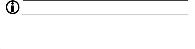
Fig III-1a: Diagram of Dialysate Chamber System
Va |
First phase of cycle: |
|
|
|
The liquid entering the left hand |
|
compartment expels an equal quantity |
|
from the right hand compartment via the |
|
diaphragm. At maximum deflection of |
|
the diaphragm, the expelled volume Va is |
|
equal to the volume of the chamber. |
Vf
Vf
|
|
|
|
Second phase of cycle: |
|
|
|
|
|
||
|
|
|
|
After the diaphragm cavity flow |
|
|
|
|
|
directions have been reversed, the liquid |
|
|
|
|
|
entering the right hand compartment |
|
|
|
|
|
expels the same quantity from the left |
|
|
|
|
|
hand compartment via the diaphragm. At |
|
|
|
|
|
maximum deflection of the diaphragm, |
|
|
|
|
|
the expelled volume Vf is equal to the |
|
Va |
|||||
volume in the chamber. |
|||||
In the two described cases the volume expelled from either compartment equals exactly the total volume of the chamber:
Vf = volume of chamber = Va
Vf = Va
The use of only one chamber would produce an irregular flow. In order to obtain a continuous flow of dialysate, a further chamber is switched parallel to the first chamber and operated at an inverse sequence.
2008T Technician’s Manual – 490130 Rev. H |
II-10 |

Section II – Hydraulic Description
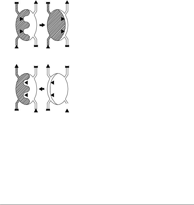
Figure III-1b: Dialysate Balancing Chamber (Phases of One Chamber)
It is insured that the same amount of dialysate is always fed to the dialyzer and discharged by the dialyzer.
|
S |
F |
|
|
1 |
|
DIALYZER |
|
S |
F |
|
|
2 |
|
|
PUMP |
|
Phase 1:
The right-hand side of the balance chamber fills with fresh dialysate. The resulting pressure on the membrane forces the spent dialysate solution out.
Phase 2:
The left hand compartment fills with used dialysate. The fresh dialysate is pressed to the dialyzer.
With just one balance chamber, dialysate would be unable to flow constantly through the dialyzer, as the two phases have to succeed one another. Therefore, the system has two balance chambers that work alternately.
2008T Technician’s Manual – 490130 Rev. H |
II-11 |
Loading...