


 Loading...
4008 HDF
Technical Manual
Fresenius Medical Care
4008 HDF
Technical Manual
4008 HDF Technical Manual
The Technical Manual contains all information necessary for performing maintenance and repair work.
The 4008 HDF option reflects the latest state of technology and complies with the requirements of EN 60601-1
Assembly, extension, adjustment, modification or repair may only be carried out by the manufacturer or persons authorized by him.
Any inquiries should be addressed to: |
|
Head office: |
Manufacturer: |
Fresenius Medical Care |
Fresenius Medical Care |
Deutschland GmbH |
Deutschland GmbH |
Borkenberg 14 |
Plant Schweinfurt |
D-61440 Oberursel/Ts., Germany |
Hafenstraße 9 |
Tel.: 06171-60-0 |
D-97424 Schweinfurt, Germany |
Telex: 410805 fres d |
Tel.: 09721-678-0 |
Fax: 06171-251-58 |
Fax: 09721-678-200 |
Local Service: |
|
|
|
|
|
Part No. 674 398 1 |
Fresenius Medical Care 4008 HDF 3/11.97 (TM) |
0-1 |
0-2 Fresenius Medical Care 4008 HDF 3/11.97 (TM)
How to use the Technical Manual
Search and find |
What? |
Where? |
|
|
Tables Contents |
Pages 0-5 and at the beginning of each chapter |
|
Purpose |
This manual is intended for: |
||
|
– first studies (to acquire basic knowledge) |
||
|
– reference purposes (for start-up, maintenance and repair) |
||
Organization |
The manual is divided into 6 chapters: |
||
|
0 |
General Notes |
|
|
1 |
Description of machine functions |
|
|
2 |
Technical safety checks |
|
|
3 |
Calibration instructions |
|
|
4 |
Circuit descriptions and circuit diagrams |
|
|
5 |
Spare parts |
|
Numbering system |
Page number 1-3 is to be interpreted as: Chapter 1, Page 3 |
||
Qualification |
This manual is intended for service technicians |
||
|
– who are familiar with the current Operating Instructions (Operating Instruc- |
||
|
|
tionseratining to this Technical Manual are available under part no. 674 406 1) |
|
|
– who have the necessary background experience in mechanics, electrical and |
||
|
|
medical engineering |
|
|
– who have been authorized by the manufacturer to perform maintenance and |
||
|
|
repair work |
|
|
– who have access to the necessary auxiliary and measuring equipment |
||
Restrictions |
The study of this manual does not represent an alternative to the training courses |
||
|
offered by the manufacturer. |
||
Manual changes |
Manual changes will be released as new editions, supplement sheets or product |
||
|
information. |
|
|
Note:
Modifications relating to circuit diagrams and component layouts (SP/BP) do not necessarily involve a change of the footer (edition).
Refer to the index field of the respective circuit diagram or component layout for the respective state of these diagrams. The identification on the P.C.B. permits the user/technician to verify if the circuit diagram / component layout matches the P.C.B. actually installed.
In general, this manual is subject to modification.
Fresenius Medical Care 4008 HDF 3/11.97 (TM) |
0-3 |
Representation |
New circuit symbols are used in the circuit diagrams. Potential data given in the |
||||||
|
circuit diagrams and setting instructions refer to the respective earth. |
||||||
Component marking |
For example: |
|
|
24 means ground for 24 V voltage. |
|||
|
|
||||||
Example: |
75 |
|
|
||||
in circuit diagrams |
|
|
|
|
|
|
|
|
|
|
|
|
|
|
|
|
|
|
|
|
|
|
|
|
|
|
|
|
|
|
|
1R5
This refers to a resistor with a position number 75 with a resistance of 1.5 Ohm.
The decimal point is replaced by a unit symbol (to reduce the possibility of errors).
|
Resistors: |
Capacitors: |
|
||
|
R1: |
0.1 Ω |
µ 1: |
0.1 µ |
F |
|
1R5: |
1.5 Ω |
1µ 5: |
1.5 µ |
F |
|
1K5: |
1.5 kΩ |
1000µ : |
1000 µ F |
|
Note: |
When repairing or exchanging replacement parts make sure to take the applica- |
||||
|
ble ESD precautions (e.g. EN 100 015-1). |
||||
|
During repair/troubleshooting in the hydraulic unit, protect the components from |
||||
|
dialysate. |
|
|
|
|
Technical data: The technical data for the 4008 HDF option is to be found in Chapter 1 of the Operating Instructions.
0-4 Fresenius Medical Care 4008 HDF 3/11.97 (TM)
Table of contents
Section |
|
Page |
1 |
Description of machine functions ............................................................................... |
1- |
1.1 |
Description ...................................................................................................................... |
1-3 |
1.2 |
Description of extended T1 test ...................................................................................... |
1-8 |
1.3 |
Error messages ............................................................................................................... |
1-10 |
2 |
Technical safety checks ............................................................................................... |
2- |
3 |
Calibration instructions ............................................................................................... |
3- |
3.0 |
General information on the calibration instructions ....................................................... |
3-3 |
3.1 |
Calibrating the UF2 pump ............................................................................................... |
3-5 |
3.2 |
VDE inspections.............................................................................................................. |
3-7 |
3.3 |
Calibrating the 4008 HDF scale ...................................................................................... |
3-8 |
3.4 |
Calibrating the substituate sensor .................................................................................. |
3-13 |
3.5 |
Calibrating the HDF blood pump .................................................................................... |
3-15 |
3.6 |
Repair instructions .......................................................................................................... |
3-17 |
4 |
Circuit descriptions and circuit diagrams .................................................................. |
4- |
4.1 |
LP 625 display board ...................................................................................................... |
4-3 |
4.2 |
LP 754 control board HDF .............................................................................................. |
4-9 |
4.3 |
LP 760 HDF motor control .............................................................................................. |
4-19 |
4.4 |
LP 761 HDF drive keyboard ........................................................................................... |
4-27 |
4.5 |
LP 762 scale comm ........................................................................................................ |
4-33 |
4.6 |
LP 763 SSE serial interface extender ............................................................................. |
4-39 |
5 |
Spare parts .................................................................................................................... |
5- |
5.0 |
How to use the spare parts catalog ................................................................................ |
5-3 |
5.1 |
P.C.B.s ............................................................................................................................ |
5-4 |
5.2 |
Scales ............................................................................................................................. |
5-6 |
5.3 |
Substituate lift ................................................................................................................. |
5-8 |
5.4 |
UF2 pump / blood pump (HDF) / valve V 126 ................................................................. |
5-10 |
Fresenius Medical Care 4008 HDF 3/11.97 (TM) |
0-5 |
0-6 Fresenius Medical Care 4008 HDF 3/11.97 (TM)
Table of contents
1 Description of machine functions
Section |
|
Page |
1.1 |
Description .................................................................................................................... |
1-3 |
1.1.1 |
Components .................................................................................................................... |
1-3 |
1.1.2 |
Description ...................................................................................................................... |
1-3 |
1.1.3 |
Component tests ............................................................................................................. |
1-3 |
|
Fig.: Block diagram ......................................................................................................... |
1-4 |
|
Fig.: Flow diagram .......................................................................................................... |
1-5 |
|
Fig.: Flow diagram .......................................................................................................... |
1-6 |
1.2 |
Description of extended T1 test / error messages in T1 test ................................... |
1-8 |
1.2.1 |
Test UF-Function ............................................................................................................ |
1-8 |
1.3 |
Error messages during treatment and the HDF test ................................................ |
1-10 |
1.4 |
Error messages, substituate pump ............................................................................. |
1-13 |
Fresenius Medical Care 4008 HDF 3/11.97 (TM) |
1-1 |
1-2 Fresenius Medical Care 4008 HDF 3/11.97 (TM)
1.1Description
1.1.1Components
The components of the 4008 HDF option are permanently connected to the hemodialysis machine. The 4008 HDF option comprises the following components:
–Substituate lift
–Scales (weighing range < 20 kg) with data interface and taring facility
–Substituate pump with bidirectional data interface
–UF2 pump
1.1.2Description
The scales determine the actual weight of the substituate reserve and signals this to the hemodialysis machine. This calculates the substituate rate depending on the set treatment time.
A substituate sensor mounted on the substituate lift recognises whether:
–Line set is fitted without substituate or
–Line set is fitted with substituate.
The substituate pump delivers the substituate solution to the venous bubble catcher. The filtrate from the dialysis fluid circuit is removed by the UF2 pump.
1.1.3Component tests
The scales are checked by the operator by means of a plausibility test before treatment. The substituate sensor is tested while the 4008 HDF is filling.
The 4008 HDF test tests:
–The substituate pump
–The UF2 pump (electrically and hydraulically)
(If the 4008 HDF test is not carried out then the connections are to be tested but once). The UF2 pump is tested cyclically during treatment.
The electric control system of the UF2 pump is checked continuously.
Fresenius Medical Care 4008 HDF 3/11.97 (TM) |
1-3 |
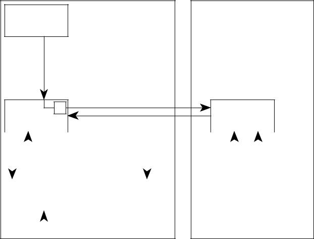
Fig.: Block diagram
Scales
 Serial communication
W
CPU 1
Operating system |
Safety system |
Serial communication |
CPU 2 |
|
|
|
|
|
|
|
|
|
|
|
|
|
|
|
|
|
|
|
|
|
|
|
|
|
|
|
|
|
|
|
|
|
|
|
|
|
Serial communication |
|
|
|
|
|
|
|
|
|||
|
|
|
|
|
|
|
|
|
|
|
|
|
|
|
|
|
|
|
|
|
|
|
|
|
|
|
|
|
|
|
|
|
|
|
|
|
|
|
|
|
|
|
|
|
|
|
|
|
UF2 pump |
|
|
Substituate |
|
|
|
|
|
TMP |
|||||
|
|
|
pump |
|
|
|
|
|
|||||||
|
|
|
|
|
|
|
|
|
|
|
|
|
|||
|
|
|
|
|
|
|
|
|
|
|
|
|
|
|
|
|
|
|
|
|
|
|
|
|
|
|
|
|
|
|
|
|
|
|
|
|
|
|
|
|
|
|
|
|
|
|
|
|
|
|
|
|
|
|
|
|
|
|
|
|
|
|
|
1-4 Fresenius Medical Care 4008 HDF 3/11.97 (TM)
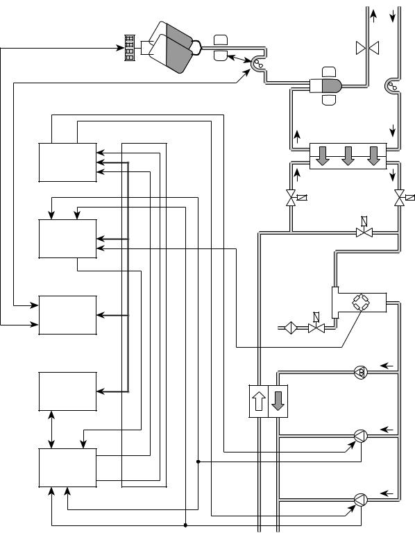
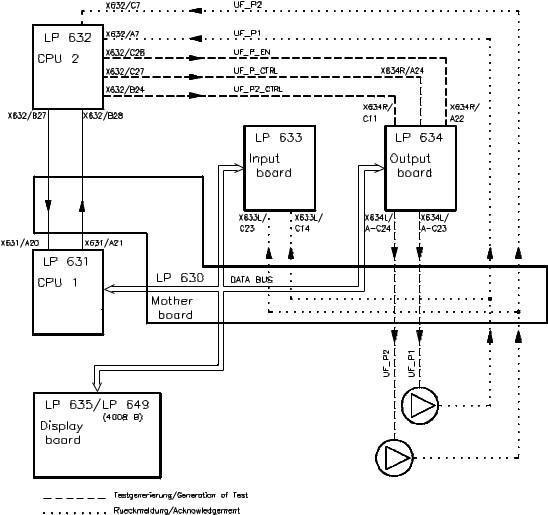
Fig.: Flow diagram
XHDF2–4 |
Scales |
Substituate bag |
Substituate sensor |
|
|
|
|
|
|
|
|
|
|
|
|
|
|
|
|
|
X348v/4–5 |
andtaringline |
|
X634L/ |
A–C23 |
|
|
X634L/ |
A–C24 |
X634R/ |
C11 |
|
|
|
|
|
|
|
|
serialinterface |
serialinterface |
LP634 |
Output |
board |
|
|
X634R/ |
A24 |
|
|
|
|
|
|
|
|
|
|
X633L/ |
C14 |
X633L/ |
C23 |
|
|
|
|
|
|
|
|
|
|
|
|
|
|
|
LP633 |
Input |
board |
interface |
extender |
X633R/ |
C28–30 |
pressuredialy.Acknowledgem., |
pumpUFControl, |
pumpUF2Control, |
UF2Acknowledgement,pump |
UFAcknowledgement,pump |
pumpUF2Control, |
pumpUFControl, |
dialysateAcknowledgement,pressure |
|
|
|
763LP |
SSE |
Serial |
|||||||||||||
|
|
|
X633L/ |
B6 |
|
|
|
|
|
|
|
|
|
|
|
|
|
|
|
serial LP631 |
interface |
X632/ |
A29 |
|
|
X632/ |
C27 |
|
|
|
|
|
|
|
Balancingchamber |
|
|
|
CPU1 |
|
|
|
|
|
|
|
|
|
|
|
|
|
|
|
|
LP632 |
CPU2 |
|
|
|
X632/ |
B24 |
|
|
|
|
|
|
|
|
|
|
X632/ |
C7 |
|
|
X632/ |
A7 |
|
|
|
|
|
|
|
|
|
|
|
Substituate pump |
Venousbubblecatcher |
Airdetector |
Venousline clamp |
Patient |
Arterial bloodpump |
|
|
|
Dialyzer |
|
|
V24 |
V26 |
V24b |
Dialysate |
pressure |
transducer |
V126
Flow pump
UF pump
UF2 pump
Fresenius Medical Care 4008 HDF 3/11.97 (TM) |
1-5 |

Fig.: Flow diagram
1-6 Fresenius Medical Care 4008 HDF 3/11.97 (TM)
Legend |
|
|
|
2 |
Temperature sensor |
77 |
Heat exchanger |
3 |
Temperature sensor |
78 |
Relief valve |
5 |
Float switch |
84 |
Disinfection valve |
6 |
Level sensor |
85 |
Disinfectant conncector |
7 |
Conductivity measuring cell |
86 |
Recirculation valve |
8 |
Blood leak detector |
87 |
Discharge valve |
9 |
Pressure transducer |
88 |
Multifunction block |
10 |
Reed contact for concentrate |
88a |
Degassing chamber |
12 |
Reed contact for bicarbonate |
88b |
Secondary air separator |
20 |
UF2 pump |
88c |
Primary air separator |
21 |
Flow pump |
89 |
Degassing orifice |
22 |
UF pump |
90a |
Rinse chamber concentrate |
23 |
Concentrate pump |
90b |
Rinse chamber bicarbonate |
24 |
Dialyzer valve 1 |
91 |
Rinse valve |
24b |
Dialyzer valve 2 |
92 |
Vent valve |
25 |
Bicarbonate pump |
94 |
Concentrate suction tube |
26 |
Bypass valve |
95 |
Bicarbonate suction tube |
29 |
Degassing pump |
97 |
Ventilation pump |
30 |
Drain valve |
99 |
Rinse valve |
31 |
Balancing chamber valve 1 |
100 |
Rinse valve |
32 |
Balancing chamber valve 2 |
102 |
Concentrate valve in central delivery system |
33 |
Balancing chamber valve 3 |
104 |
Bicarbonate valve in central delivery system |
34 |
Balancing chamber valve 4 |
109 |
Temperature sensor |
35 |
Balancing chamber valve 5 |
111 |
Hydrophobic filter |
36 |
Balancing chamber valve 6 |
112 |
Vent valve |
37 |
Balancing chamber valve 7 |
114 |
Dialysate filter |
38 |
Balancing chamber valve 8 |
115 |
Disinfection valve sensor |
41 |
Water inlet valve |
116 |
Sampleing valve |
43 |
Fill valve |
117 |
Check valve (concentrate) |
54 |
Heater rod |
118 |
Check valve (bicarbonate) |
61 |
Pressure reducing valve |
119 |
Filter (concentrate) |
63 |
Filter/water inlet |
120 |
Filter (bicarbonate) |
65 |
Loading pressure valve |
121 |
Concentrate connector in central delivery system |
66 |
Heater block |
122 |
Bicarbonate connector in central delivery system |
66a |
Water inflow chamber |
123 |
Pressure switch for V 102 |
66b |
Heater rod chamber |
124 |
Pressure switch for V 104 |
66c |
Float chamber |
125 |
Adapter plate |
68 |
Balancing chamber |
126 |
4008 HDF vent valve |
71 |
Filter/concentrate |
148 |
Filter/rinse valve |
72 |
Filter/bicarbonate |
149 |
Filter/rinse valve |
73 |
Filter/external dialysate |
150 |
Filter |
74 |
Filter/UF |
151 |
Orifice |
75 |
External flow indicator |
152 |
4008 HDF hydrophobic filter |
76 |
Filter/fill valve |
|
|
Hydraulic measurement points
AReduced water inlet pressure
BBalancing chamber loading pressure
CFlow pump pressure
DDegassing pump pressure
Fresenius Medical Care 4008 HDF 3/11.97 (TM) |
1-7 |
1.2Description of extended T1 test / error messages in the T1 test
Possible error messages displayed in the T1 test are listed in the Technical Manual for the hemodialysis machine. If the HDF option is installed and activated the following error codes can also appear:
1.2.1Test UF-Function Test description:
CPU 1 starts up the UF2 pump at a defined rate.
CPU 2 controls the hydraulic and electrical function of the UF2 pump. CPU 2 blocks the control line of the UF2 pump and checks for standstill. UF2 counter check.
Figure:
1-8 Fresenius Medical Care 4008 HDF 3/11.97 (TM)
Error description: |
|
|
|
|
Error message |
Description |
|
|
|
F11 UF-Function |
The interval between the strokes of the UF2 pump was less than |
|||
|
220 ms. Correct delivery of the required volume is not safeguard- |
|||
|
ed because the stroke return travel is too short. |
|||
|
– A pump rate which was too high was signalled by the CPU 1. |
|||
F12 UF-Function |
The pulse time for the UF2 pump is less than 180 ms. Correct |
|||
|
delivery of the required volume is not safeguarded because the |
|||
|
discharge time is too short. |
|
|
|
|
– Monoflop on LP 634 defect (IC 42/R65/C45). |
|||
F 13 UF-Function |
The pulse for the UF2 pump is longer than 500 ms. A maximum |
|||
|
rate of 5000 ml/h is not possible. |
|
|
|
|
– Monoflop on LP 634 defect (IC 42/R65/C45). |
|||
F14 UF-Function |
UF2 pump not active during the test (4 s). |
|
|
|
|
– |
Acknowledgement (UF_P2, X637/B26) → |
X632/C7 no LOW |
|
|
|
pulse |
|
|
|
– |
Control line (UF_P2, X634L/A–C24) → |
X637/B26 no LOW |
|
|
|
pulse |
|
|
F15 UF-Function |
The UF2 pump cannot be stopped by the CPU2. |
|||
|
– |
Control line (UF_P_EN, X632/C28) → |
X634R/A22 no 5 V. |
|
|
– Reset input to IC 42/pin 13 on LP 634 defect. |
|||
F16 UF-Function |
The UF pump acknowledgement from CPU1 is faulty. |
|||
|
– |
Acknowledgement (UF_P2, X637/B26) → |
X633/C23 no LOW |
|
|
|
pulse |
|
|
F17 UF-Function |
The change in pressure after a UF2 pump stroke less than |
|||
|
20 mmHg. |
|
|
|
|
– UF2 pump mechanically defect. |
|
|
|
|
– |
Control line (UF_P2_CRTL, X632/B24) → X634R/C11 no |
||
|
|
HIGH pulse. |
|
|
F20 UF-Function |
Difference in pressure between UF pump stroke and UF2 pump |
|||
|
stroke more than 20 %. |
|
|
|
|
– Stroke rate for UF pump or UF2 pump not set correctly. |
|||
Fresenius Medical Care 4008 HDF 3/11.97 (TM) |
1-9 |
1.3Error messages during treatment and the HDF test
Message on the |
Cause |
Possible error elimination |
display |
|
|
|
|
|
F321 HDF-failure |
The UF pump or UF2 pump |
Check level sensor (6) (de- |
|
test will not be started as long |
fect). |
|
as the level sensor (6) detects |
|
|
air. The level sensor (6) will |
|
|
detect air one minute after the |
|
|
4008 HDF test has been se- |
|
|
lected |
|
|
|
|
F322 HDF-failure |
The UF pump or UF2 pump |
Check V126 (does not open, |
|
has carried out more than 50 |
venous bubble catcher col- |
|
strokes and still no air has |
lapses), check V43 (whether |
|
been detected. |
leaking or open). |
|
|
Check UF pump or UF2 pump, |
|
|
respectively (mech. defect). |
|
|
|
F323 HDF-failure |
The substituate pump runs at a |
Check substituate tubing |
|
rate of 10 ml/min. to raise the |
(clamped off, not connected to |
|
fluid level by a defined amount |
the venous bubble catcher). |
|
in the secondary air separator |
|
|
(the fluid will just be detected). |
|
|
Air will still be detected after 2 |
|
|
minutes. |
|
|
|
|
F324 HDF-failure |
Since fluid has been recog- |
Check substituate tubing |
|
nized in the secondary air sep- |
(clamped off). |
|
arator the substituate pump |
|
|
starts at a rate of 10 ml/min. |
|
|
until a change in weight follows |
|
|
on the scales (i.e. a jump in |
|
|
grammes). There was no dif- |
|
|
ference in weight established |
|
|
after one minute. |
|
|
|
|
F325 HDF-failure |
If the expected change in |
Check bag (fluctuations in air |
|
weight (i.e. a jump in |
draft) |
|
grammes) is higher or lower |
Check scales (for drifting). |
|
than –1 g, the respective UF |
|
|
pump test will be repeated. |
|
|
The UF pump test was repeat- |
|
|
ed more than 5 times. |
|
|
|
|
1-10 Fresenius Medical Care 4008 HDF 3/11.97 (TM)
Message on the |
Cause |
Possible error elimination |
display |
|
|
|
|
|
F326 UF-failure |
The fluid level in the second- |
Check substituate hose |
|
ary air separator is raised |
(clamped off, not connected |
|
again by the substituate pump |
with the venous bubble |
|
after 100 strokes of the UF |
catcher). |
|
pump or UF2 pump, respec- |
|
|
tively, until fluid is detected. |
|
|
Plus run-on time at a rate of 10 |
|
|
ml/min. for the gramme jump. |
|
|
Air will still be detected after a |
|
|
specific period of time (de- |
|
|
pending on the delivery rate of |
|
|
the substituate pump). |
|
|
|
|
UF1 volume-Error |
One UF pump did not pass the |
Check UF pump or UF2 pump, |
or |
test. The filling volume for the |
respectively (not calibrated, |
UF2 volume-Error |
secondary air separator is not |
mechanical defect). |
|
within the given tolerance of |
|
|
100 ml; ± 5 ml. Should the test |
|
|
give a reading of over 105 ml |
|
|
the cause could also be air |
|
|
taken in the flow from a badly |
|
|
vented dialysator. |
|
|
|
|
F327 UF-failure |
Interval between two strokes |
Check CPU 1 (defect). |
|
of the UF pump less than |
|
|
220 ms. |
|
|
|
|
F328 UF-failure |
Pulse time of a stroke of UF |
Check LP 634 (regulating |
|
pump less than 180 ml. |
monoflop defect). |
|
|
|
F329 UF-failure |
Pulse time of a stroke of UF |
Check LP 634 (regulating |
|
pump more than 500 ms. |
monoflop defect). |
|
|
|
F330 UF-failure |
Starting time for the UF pump |
Check LP 634 (regulating end |
|
more than 10 seconds. |
stage defect). |
|
|
|
F331 UF-failure |
Difference between desired or |
Check CPU 1 / CPU 2 |
|
actual delivery rate of the UF |
(communication problems). |
|
pump greater than + 10%. |
|
|
|
|
F332 UF-failure |
UF pump stops longer than the |
Check LP 634 (regulating end |
|
maximum period time. |
stage defect). |
|
|
Check UF pump |
|
|
(interruption, control). |
|
|
Check CPU 1 / CPU 2 |
|
|
(communication problems) |
|
|
|
F333 UF-failure |
Despite switched off ultrafiltra- |
Check CPU 1 / CPU 2 |
|
tion the change in delivery rate |
(communication problems) |
|
of the UF pump is greater than |
|
|
10 ml. |
|
|
|
|
F334 UF-failure |
Interval between two strokes |
Check CPU 1 (defect). |
|
of the UF2 pump less than |
|
|
220ms. |
|
|
|
|
Fresenius Medical Care 4008 HDF 3/11.97 (TM) |
1-11 |
Message on the |
Cause |
Possible error elimination |
|
display |
|
|
|
|
|
|
|
F335 |
UF-failure |
Pulse time of a stroke of the |
Check LP 634 (regulating |
|
|
UF2 pump less than 180 ms. |
monoflop defect). |
|
|
|
|
F336 |
UF-failure |
Pulse time of a stroke of the |
Check LP 634 (regulating |
|
|
UF2 pump more than 500 ms. |
monoflop defect). |
|
|
|
|
F337 |
UF-failure |
Reaction time of the UF2 |
Check LP 634 (regulating end |
|
|
pump more than 10 seconds. |
stage defect). |
|
|
|
|
F338 |
UF-failure |
Difference in desired or actual |
Check CPU 1 / CPU 2 |
|
|
delivery rate of UF2 pump |
(communication problems). |
|
|
greater than ± 10 %. |
|
|
|
|
|
F339 |
UF-failure |
UF2 pump stops longer than |
Check LP 634 (regulating end |
|
|
the maximum period time. |
stage defect). |
|
|
|
Check UF pump (interruption, |
|
|
|
control). |
|
|
|
Check CPU 1 / CPU 2 |
|
|
|
(communication problems). |
|
|
|
|
F340 |
UF-failure |
Despite switched off 4008HDF |
Check CPU 1 / CPU 2 |
|
|
change in delivery rate of the |
(communication problems). |
|
|
UF2 pump greater than 10 ml. |
|
|
|
|
|
F341 |
UF-failure |
Failure of UF pump. |
Check UF pump |
|
|
|
(spring, screen) |
|
|
|
|
F342 |
UF-failure |
Failure of UF2 pump. |
Check UF2 pump |
|
|
|
(spring, screen) |
|
|
|
|
F343 |
UF-failure |
Volume difference between UF |
Check UF pump and UF2 |
|
|
pump and UF2 pump. |
pump (delivery volume) |
|
|
|
|
F344 |
HDF-failure |
Balance failure recognized by |
Check monitor / scales |
|
|
CPU2 greater than ± 500 ml. |
(communication problems). |
|
|
|
|
F345 |
HDF-failure |
Bolus exceeded by more than |
Check monitor / scales |
|
|
+ 20 ml, detected by CPU2. |
(communication problems). |
|
|
|
|
F346 |
HDF-failure |
CPU2 failed to perform the cy- |
Check V24B and V43 feed- |
|
|
clic UF pump test within 5 min- |
back lines. |
|
|
utes. |
Check sense of rotation of as- |
|
|
|
piration pump. |
|
|
|
Check hydraulics unit for |
|
|
|
leaks. |
|
|
|
|
F348 |
HDF-failure |
Weight change on the scales |
Check scales |
|
|
during the weighing test great- |
Check substituate bag |
|
|
er than 2g. |
|
|
|
|
|
F349 |
HDF-failure |
The delivery rate correction |
Check substituate bag |
|
|
factor could still not be deter- |
(weight fluctuations) |
|
|
mined after 20 minutes treat- |
Check HDF control system |
|
|
ment time. |
(greater fluctuations) |
|
|
|
|
1-12 Fresenius Medical Care 4008 HDF 3/11.97 (TM)
1.4Error messages, substituate pump
Code |
Description of failure |
|
|
E.01 |
Line diameter outside the permitted range |
|
|
E.02 |
Non-defined hexaswitch position |
|
|
E.03 |
Venous pressure transducer not balanced |
|
|
E.04 |
Failure, running time monitoring system, SN operation |
|
|
E.05 |
SN stroke volume outside the permitted range |
|
|
E.06 |
The SN pressure thresholds outside the value range of the AD converter |
|
|
E.07 |
Not defined |
|
|
E.08 |
Failure in the AD conversion |
|
|
E.09 |
Not defined |
|
|
E.10 |
Not defined |
|
|
E.11 |
Not defined |
|
|
E.12 |
Failure, speed monitoring (hall sensor) |
|
|
E.13 |
Failure, monitoring system, current sensing resistors |
|
|
E.14 |
Failure, monitoring system, current sensing resistors |
|
|
E.15 |
Failure, speed monitoring system |
|
|
Fresenius Medical Care 4008 HDF 3/11.97 (TM) |
1-13 |
1-14 Fresenius Medical Care 4008 HDF 3/11.97 (TM)
2 Technical safety checks
General Notes
This chapter includes all necessary technical safety checks (TSC).
These inspections must be carried out every 12 months.
The technical safety inspections stipulated for the hemodialysis machine must be carried out in addition to these technical saftey checks.
The technical safety checks are to be recorded in the equipment log.
A technical safety checks report is to be found at the page 2-3.
Fresenius Medical Care 4008 HDF 3/11.97 (TM) |
2-1 |
2-2 Fresenius Medical Care 4008 HDF 3/11.97 (TM)

|
|
|
Technical safety checks report |
Seite 1/1 |
|
|
|
|
|
|
|
Manufacturer: ............................. |
Date: ............................. |
Machine: ............................. |
Technician: ............................. |
Operating hours: ............................. |
|
Extent of checks and time limits for technical safety checks.
TIME LIMIT: every 12 months
The following checks and inspections have to be carried out on the machine at least every 12 months by persons who are capable of carrying out such technical safety checks efficiently as a result of their training, knowledge and experience gained in practice and are not subject to instructions as to their checking activity.
(See also BMA Bulletin dated 02.04.1987)
TSC |
WA |
No. |
Description |
Desired value/function |
OK |
|
|
|
|
|
|
|
|
1 |
UF2 pump |
|
|
|
|
|
|
|
|
TSC |
|
1.1 |
Delivery volume (1 ml/stroke) |
60 strokes = 60 ml ± 1 % |
|
|
|
|
|
|
|
|
|
2 |
VDE inspections (values according to EN 60601-1) |
|
|
|
|
|
|
|
|
TSC |
|
2.1 |
Protective ground resistance |
max. 0.3 Ω |
|
|
|
|
|
|
|
TSC |
|
2.2 |
Summarized leakage current |
Must fulfill both conditions: |
|
|
|
|
|
1. No more than 1.5 times the “summari- |
|
|
|
|
|
zed value first measured” |
|
|
|
|
|
(“Summarized value first measured”: |
|
|
|
|
|
Refer to the machine card enclosed with |
|
|
|
|
|
the machine.) |
|
|
|
|
|
2. No more than 1 mA |
|
|
|
|
|
|
|
The technical safety checks are to be recorded in the equipment log and the results of the checks documented.
If the machines are not safe in function and/or operation they are to be repaired or the operator is to be informed as to the dangers involved when using the machine in its given state.
The correct completion of the listed work and the correctness of statements made are hereby certified.
Signature, technician: |
Signature, customer: |
........................... , date ............................. |
................................ , date ............................. |
.................................................................... |
......................................................................... |
Fresenius Medical Care 4008 HDF 3/11.97 (TM) |
2-3 |
2-4 Fresenius Medical Care 4008 HDF 3/11.97 (TM)
Table of contents
3 Calibration instructions
Section |
|
Page |
3.0 |
General information on the calibration instructions ................................................ |
3-3 |
3.1 |
Calibrating the UF2 pump ............................................................................................ |
3-5 |
3.2 |
VDE inspections ............................................................................................................ |
3-7 |
3.3 |
Calibrating the 4008 HDF scales ................................................................................. |
3-8 |
3.4 |
Calibrating the substituate sensor .............................................................................. |
3-13 |
3.5 |
Calibrating the HDF blood pump ................................................................................. |
3-15 |
3.5.1 |
Pressure transducer ....................................................................................................... |
3-15 |
3.5.2 |
Checking SN switchover points ...................................................................................... |
3-16 |
3.6 |
Repair instructions ....................................................................................................... |
3-17 |
Fresenius Medical Care 4008 HDF 3/11.97 (TM) |
3-1 |
3-2 Fresenius Medical Care 4008 HDF 3/11.97 (TM)
3.0General information on the calibration instructions
Measuring instruments:
The same measuring instruments as used for the hemodialysis machines are to be employed. Required in addition is a calibration weight PT6 – 5000 g.
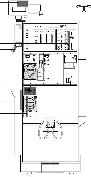
Fig.: P.C.B. overview 4008 HDF
LP 762
LP 763 LP 761
Fresenius Medical Care
Fresenius Medical Care 4008
|
|
|
|
|
|
|
|
Best. |
Auswahl |
|
|
|
I/O |
|
Arterieller |
|
Venöser |
|
|
|
|
|
|
|
|
Luftdetektor |
|
|
|
TMP |
Ultrafiltration |
Leitfähigkeit |
|
Fluß |
||||
|
Druck |
|
Druck |
|
|
|||||||
|
|
|
|
|
|
|
UF Menge |
ml |
|
|
|
ml/min |
Spülen |
|
|
|
|
|
|
|
Reset |
|
|
|
900 |
|
|
|
|
|
|
|
|
|
|
mS/cm |
|
700 |
|
kPa |
mmHg |
kPa |
mmHg |
kPa |
mmHg |
|
|
|
(25° C) |
|
500 |
Heiß reinigen |
|
280 |
|
500 |
|
500 |
|
|
|
15.5 |
|
300 |
Blutleck |
30 |
200 |
60 |
|
60 |
|
UF Rate |
ml/h |
|
|
|
|
|
|
|
400 |
|
400 |
|
|
|
15 |
|
|
|
Desinfektion |
20 |
100 |
50 |
50 |
|
|
|
|
|
|||
|
10 |
40 |
300 |
40 |
300 |
|
|
|
14.5 |
I/O |
Set |
|
|
0 |
0 |
|
|
|
|
|
|||||
Single |
30 |
200 |
30 |
200 |
|
|
|
14 |
|
|
||
–10 |
–100 |
|
|
|
|
|
|
|
||||
Needle |
|
20 |
100 |
20 |
100 |
UF Ziel |
ml |
|
13.5 |
|
|
|
Ü berbrücken |
–20 |
–200 |
10 |
10 |
|
|
|
|
|
|||
Test |
–30 |
|
0 |
0 |
0 |
0 |
|
|
|
13 |
Temperatur |
|
|
–40 |
–300 |
|
|
|
|
|
|
|
|
|
° C |
Vorbereiten |
|
|
|
|
|
|
UF Restzeit h:min |
Konz. |
Bic. |
|
39 |
|
|
|
|
|
|
|
|
|
|
|
37 |
||
Dialyse Start |
|
|
|
|
|
|
|
|
|
|
|
35 |
|
|
|
|
|
|
|
UF |
|
Variation |
|
|
|
Alarm |
|
|
|
|
|
|
I/O |
Prog. |
I/O |
Prog. |
|
Set |
Ton Aus |
|
|
|
|
|
|
|
|
|
|
|
|
|
|
|
|
|
|
|
|
|
Pven. |
|
|
|
|
|
|
Bolus |
|
|
|
|
|
|
|
|
|
Start |
|
|
Rate |
|
|
|
|
|
|
|
|
|
Stop |
|
|
|
|
|
|
|
|
|
|
|
|
Start
Stop
LP 625
Start
Stop
LP 760
LP 754
Fresenius Medical Care 4008 HDF 3/11.97 (TM) |
3-3 |

Fig.: DIP switch 4008 HDF
SW1
ON
1 2 3 4 5 6 7 8
OFF
LP 632 CPU 2
SW 1, DIP switch 8:
ON: 4008 HDF test selectable (required/not required) OFF: 4008 HDF test carried out automatically
3-4 Fresenius Medical Care 4008 HDF 3/11.97 (TM)
Loading...