


 Loading...
TECHNICAL MANUAL
TECHNICAL
MANUAL
PILOT A2, CE2 RS232 Events log
From serial n° 17730124 till ...
Revision table
TM Pilot A2 CE2 RS 232 Events Log_en : ref NT 1734
Date |
Revision |
Chapter |
Description |
|
|
|
|
03/04/03 |
0 |
All index "a" |
Creation |
|
|
|
|
08/01/07 |
1 |
index "b" |
New EMC standard, spare parts up date |
|
|
|
|
|
|
|
|
|
|
|
|
|
|
|
|
|
|
|
|

1 Overview ........................................................................................................... |
|
7 |
1.1 |
General .................................................................................................... |
7 |
1.2 |
Overview diagram ................................................................................. |
8 |
1.3 |
Precautions to be taken before use...................................................... |
9 |
1.4 |
Internal safety features .......................................................................... |
9 |
1.5 |
Technical characteristics ...................................................................... |
9 |
1.5.1 |
Electrical specifications .............................................................................................. |
9 |
1.5.2 |
Electronic specifications............................................................................................. |
9 |
1.5.3 |
Mechanical specifications .......................................................................................... |
9 |
1.5.4 |
Conformity and norms.............................................................................................. |
10 |
2 Description and operation ............................................................................. |
11 |
|
2.1 Physical description ............................................................................ |
11 |
|
2.1.1 The display board and the front panel...................................................................... |
12 |
|
2.1.2 |
CPU board ............................................................................................................... |
14 |
2.1.3 The power supply board and the battery.................................................................. |
17 |
|
2.1.4 Mechanical gear box unit ......................................................................................... |
20 |
|
2.1.5 |
Mechanical plunger unit ........................................................................................... |
20 |
2.2 Functional description ......................................................................... |
21 |
|
2.2.1 Syringe control and maintenance assembly ............................................................ |
21 |
|
2.2.2 |
Motorisation assembly ............................................................................................. |
21 |
2.2.3 |
External connection sub-assembly .......................................................................... |
21 |
3 Description of the menus .............................................................................. |
23 |
|
3.1 Configuration menu of the current operation parameters ............... |
23 |
|
3.1.1 |
Menu access ............................................................................................................ |
24 |
3.1.2 |
PAr1, configuration of the memorisation type ...................................................... |
25 |
3.1.3 |
PAr2, configuration of the syringe selection type ................................................. |
25 |
3.1.4 |
PAr3, |
|
|
configuration of the maximum flow rate that may be selected on the keyboard ...... |
26 |
3.1.5 |
PAr4, configuration of the list of syringes that may be selected........................... |
26 |
3.1.6 |
PAr5, configuration of the compulsory priming .................................................... |
27 |
3.1.7 |
PAr7, configuration of the KVO flow rate ............................................................. |
27 |
3.1.8 |
PAr9, configuration of the RS232 communication speed..................................... |
28 |
3.1.9 |
PArA, configuration of the empty syringe mode ................................................... |
28 |
3.1.10 |
PArb, configuration of the frequency of preventive checks .................................. |
29 |
3.1.11 |
PArC, configuration of the drug display mode ...................................................... |
29 |
3.1.12 |
PArd, configuration of the Flanges detection mode ............................................. |
30 |
3.1.13 |
PArF, configuration of the bolus flow memorisation mode ................................... |
30 |
3.1.14 |
PArG, configuration of the drugs list ..................................................................... |
31 |
3.1.15 |
PArJ, configuration of the mains disconnection signal......................................... |
32 |
3.1.16 |
PAr0, configuration of the date and time.............................................................. |
32 |
3.1.17 Typical syringe/details correspondence table .......................................................... |
33 |
|
PiloteCE2_A2_RS232horodaté_enTDM.fm |
3 |
|
|

3.2 Calibration menu.................................................................................. |
35 |
|
3.3 Service test menu ................................................................................ |
37 |
|
4 Preventive maintenance................................................................................. |
39 |
|
4.1 Recommendations ............................................................................... |
39 |
|
4.2 Maintenance schedule......................................................................... |
39 |
|
4.2.1 |
Preventive maintenance........................................................................................... |
39 |
4.2.2 |
Quality control .......................................................................................................... |
39 |
4.3 Checks .................................................................................................. |
41 |
|
4.3.1 |
Test access .............................................................................................................. |
41 |
4.3.2 |
Visual check ............................................................................................................. |
41 |
4.3.3 |
Running time and last servicing inspection date ...................................................... |
42 |
4.3.4 |
Indicator lights check................................................................................................ |
42 |
4.3.5 |
Keyboard check ....................................................................................................... |
43 |
4.3.6 |
Checking the battery voltage.................................................................................... |
44 |
4.3.7 |
Display of the last 10 alarms .................................................................................... |
44 |
4.3.8 |
Total operation time check ....................................................................................... |
46 |
4.3.9 |
TTL serial link test .................................................................................................... |
46 |
4.3.10 |
RS 232 serial link check........................................................................................... |
47 |
4.3.11 |
Checking the software version. ................................................................................ |
47 |
4.3.12 |
Checking the ADC.................................................................................................... |
48 |
4.3.13 |
Checking the position sensor ................................................................................... |
48 |
4.3.14 |
Buzzer test ............................................................................................................... |
49 |
4.3.15 |
Display of the calibration values............................................................................... |
49 |
4.3.16 |
Checking the syringe clamp ..................................................................................... |
49 |
4.3.17 |
Checking the syringe group number ........................................................................ |
50 |
4.3.18 |
Checking the list of syringes .................................................................................... |
50 |
4.3.19 |
Checking the disengagement................................................................................... |
50 |
4.3.20 |
Checking the flanges detection system.................................................................... |
50 |
4.3.21 |
Checking the syringe head detection system........................................................... |
51 |
4.3.22 |
Checking backpressure............................................................................................ |
52 |
4.3.23 |
Checking the pre-alarm and end of infusion alarm .................................................. |
52 |
4.3.24 |
Checking the linearity............................................................................................... |
53 |
4.3.25 |
Checking mains/battery operation............................................................................ |
53 |
4.3.26 |
Battery autonomy test .............................................................................................. |
54 |
4.3.27 |
Continuity test .......................................................................................................... |
54 |
4.3.28 |
Quality Control Certificate ........................................................................................ |
55 |
4.4 Flow rate control .................................................................................. |
57 |
|
4.4.1 |
Measurement with a computer................................................................................. |
57 |
4.4.2 |
Measurement with scales......................................................................................... |
59 |
4.4.3 |
Measurement using a test tube................................................................................ |
61 |
4.5 Cleaning and disinfecting ................................................................... |
63 |
|
4.6 Storage.................................................................................................. |
64 |
|
|
44 |
PiloteCE2_A2_RS232horodaté_enTDM.fm |
|
|
|

5 |
Diagnostic ....................................................................................................... |
|
65 |
|
5.1 |
Troubleshooting guide ....................................................................... |
65 |
|
5.2 |
Error messages .................................................................................... |
67 |
6 |
Operation sheets ............................................................................................ |
71 |
|
|
N°1, Procedure: Display and central unit boards .................................... |
73 |
|
|
N°2, Procedure: Syringe clamp ................................................................. |
75 |
|
|
N°3, Procedure: Syringe detection system .............................................. |
77 |
|
|
N°4, Procedure: Motor + Opto + Disk ........................................................ |
83 |
|
|
N°5, Procedure: Dynamometer sensor ..................................................... |
85 |
|
|
N°6, Procedure: Plunger advance control potentiometer ....................... |
91 |
|
|
N°7, Procedure: |
|
|
|
|
Plunger cover and/or disengagement lever + anti-siphon arm .... |
.. 93 |
|
N°8, Procedure: Power supply board........................................................ |
95 |
|
|
N°9, Procedure: Battery door and battery ................................................ |
97 |
|
|
N°10, Procedure: Plug holder wired .......................................................... |
99 |
|
|
N°11, Procedure: Ribbon cable winding kit............................................ |
101 |
|
|
N°12, Procedure: Syringe head detection plunger kit ........................... |
105 |
|
|
N°13, Procedure: Centering ring kit ........................................................ |
109 |
|
|
N°14, Procedure: Flex circuit and tube kit .............................................. |
113 |
|
|
N°15, Procedure: Upper and lower cases ............................................... |
119 |
|
7 |
Calibration..................................................................................................... |
|
123 |
|
7.1 |
Calibration procedure ........................................................................ |
123 |
|
7.1.1 |
Calibration access.................................................................................................. |
123 |
|
7.1.2 EtA.4 Calibration of the 3 battery voltage levels................................................ |
124 |
|
|
7.1.3 EtA.6 Calibration of the position sensor. ........................................................... |
124 |
|
8 |
Spare parts catalogue .................................................................................. |
125 |
|
|
8.1 |
Upper case .......................................................................................... |
125 |
|
8.2 |
Lower case .......................................................................................... |
127 |
|
8.3 |
Plunger unit ........................................................................................ |
129 |
|
8.4 |
Mechanical Gear box ......................................................................... |
133 |
|
8.5 |
Labels .................................................................................................. |
135 |
PiloteCE2_A2_RS232horodaté_enTDM.fm |
5 |
|
|

|
66 |
PiloteCE2_A2_RS232horodaté_enTDM.fm |
|
|
|

1 Overview
1.1 General
The Pilot A2 RS 232 Events log is a syringe pump intended for the infusion of intravenous agents at a accurate, low flow rate. The wide choice of syringes, the use of the universally recognised control symbols and the synoptic display of the alarms contribute to making the Pilot A2 RS 232 Events log easy to use. The adjustable occlusion detection, the correct positioning detection and the overall syringe protection system guarantee optimum safety.
Its technical characteristics, the flow range from 0.1 to 400 ml/hr (configured at 200 ml/hr) and its excellent accuracy (+1% on the device) contribute to making the Pilot A2 RS 232 Events log, the ideal instrument for medical services.
The Pilot A2 RS 232 Events log is equipped with a 16ko-EEPROM enabling the memorization of 896 events. These events are available for consultation through the ISCTRL maintenance software, 4.1 and upper version.
Overview
01_011b_en.fm |
7 |
|
|

1.2 Overview diagram
Ext |
|
|
|
|
|
|
12/15 V |
|
|
|
|
|
|
15 W |
|
|
|
|
|
|
|
|
|
DC-DC |
Motor |
Step by |
|
230 V |
Power supply |
ON / OFF |
step |
|||
converter |
driver |
|||||
|
|
|
motor |
|||
|
|
|
|
|
||
|
Battery |
|
|
|
|
|
EPROM |
|
|
|
|
|
|
128K x 8 |
|
|
|
|
|
|
|
RAM |
|
|
|
Motor speed |
|
|
8K x8 |
|
|
|
||
|
|
|
|
sensor |
||
|
|
|
|
|
||
|
EEPROM |
|
|
|
|
|
|
512 |
|
|
|
Syringue body |
|
|
|
|
|
|
||
|
|
|
|
|
sensor |
|
|
BUS |
|
|
|
Antisiphon |
|
|
|
|
|
|
||
|
SPI |
CPU |
|
|
sensor |
|
|
|
|
|
|||
|
|
Watch |
|
|
||
|
|
|
|
|
||
|
|
|
dog |
|
Displacement |
|
|
|
|
|
|
transducer |
|
UART |
Interface |
|
Opto |
|
|
|
bus |
|
interface |
|
|
||
|
|
|
Nurse call |
|||
|
|
|
|
|
||
|
|
|
|
|
(option) |
|
|
|
|
ADC |
|
|
|
|
|
|
|
|
Occlusion |
|
|
|
|
|
|
switch |
|
|
|
|
|
|
Disengagement |
|
|
|
|
|
|
switch |
|
|
|
|
LCD |
LCD |
|
|
|
|
|
display |
|
||
RS 232 |
Keyboard |
|
driver |
|
||
|
|
|
||||
|
|
|
|
Flanges switch |
||
|
|
|
|
|
||
|
Master |
|
LED |
LED |
|
|
|
Buzzer |
driver |
display |
|
||
|
|
|
||||
Overview |
|
|
|
|
|
|
8 |
|
|
|
|
01_011b_en.fm |

1.3 Precautions to be taken before use
The symbol ! in the concise instrument instructions guide of the device recommends that the operator’s guide should be read complelety in accordance with standard EN 60601-1.
Fresenius Vial may in no case be held responsible for medical problems or any other problems resulting from inadequate use of the equipment.
Refer to the User’s instructions for further details.
1.4 Internal safety features
As soon as it is switched ON, the device activates a continuous function inspection system. Any internal failure or any problem related to the operating procedure in progress is detected immediately. Nevertheless, abnormal operation of the equipment with no obvious cause must always be reported to the qualified technicians in your establishment or our After Sales service.
In case of single fault condition, an alarm is activated for any flow rate deviation of ± 5% in comparison with the normal flow rate.
A second check activates an alarm in the event of deviation of 1 ml in comparison with the anticipated infused volume, or if a flow rate deviation of ± 20% is identified. The alarm is triggered by the most rapidly detected deviation.
The Pilot A2 Events log is fitted with an internal battery to continue operation in the event of a power cut. Furthermore, a safety fuse protects the mains from further disturbance.
1.5Technical characteristics
1.5.1Electrical specifications
!Power supply: 230 V - 50-60 Hz.
!Max. consumption : 23 VAC.
!Fuse F2: 100 mAT 250 V IEC 127.
!Battery: 6 V - 1,1 / 1,3 Ah.
!External power supply: 12 - 15 V DC -15 W.
1.5.2 Electronic specifications
The Pilot syringe pump is fitted with 3 circuit boards:
!Motor power supply and control board.
!CPU board.
!Keyboard display board.
1.5.3 Mechanical specifications
!Overall dimensions H x W x D: 120 x 330 x 155 mm.
!Weight: approximately 2,2 kg.
Overview
01_011b_en.fm |
9 |
|
|

|
1.5.4 Conformity and norms |
|
|
|
|
|
Conform to the 93/42/CE Medical Directive. |
IP34 Protection against |
0459 |
|
splashing liquid. |
Safety of Electro |
Conform to EN/IEC 60601-1 and EN/IEC 60601-2-24 |
Protection against |
Medical |
|
leakage current: CF type. |
Equipements |
|
|
EMC |
Conform to EN/IEC 60601-1-2 (first edition) and EN/IEC |
Protection against electric |
(ElectroMagnetic |
60601-2-24 |
shocks: class II. |
Compatibility) |
|
|
Since 2001,electromagnetic compatibility standards have evolued.
Pilot A2 RS 232 Events log that serial number is higher than 18908961 with EN/IEC 60601-1-2 (second édition) and EN/IEC 60601-2-24 complies standards.
Detailed information concerning electromagnetic compatibility is available in the chapter "Guidance and manufactureris declaration on EMC" of the User Manual.
Overview
|
10 |
01_011b_en.fm |
|
|
|
2Description and operation
2.1Physical description
|
|
|
|
|
|
|
|
|
|
|
|
|
|
|
|
|
|
|
|
|
|
|
|
|
|
|
|
|
|
|
|
|
Flanges switch |
|
|
|
Flanges positioning groove |
|
|||
|
|
Syringe clamp |
|
|
|
Plunger disengagement |
|||||||
|
|
|
|
|
|
|
|
|
|||||
|
|
|
|
|
|
||||||||
|
Upper case |
|
|
|
control |
|
|
|
|||||
|
|
|
|
|
|
|
|||||||
|
|
|
|
|
|
|
|
|
Anti-siphon arm |
|
|
|
|
|
|
|
|
|
|
|
|
|
|
|
|
||
|
|
|
|
|
|
|
|
|
|
|
|
|
|
|
|
|
|
|
|
|
|
|
|
|
|
|
|
|
|
|
|
|
|
|
|
|
|
|
|
|
|
|
|
|
|
|
|
|
|
|
|
|
|
|
|
|
|
|
|
|
|
|
|
|
|
|
|
|
|
|
|
|
|
|
|
|
|
|
|
|
|
|
|
Lower case |
Front control panel |
|
The Pilot A2 Events log is fitted with an upper case and a lower case.
!The upper case holds the syringe clamp and contains:
"A display board associated with the front control panel.
"A CPU board.
!The lower case contains:
"A power supply board and a battery.
"A mechanical base unit.
"A plunger unit.
Description and operation
02_008b_en.fm |
11 |
|
|
Description and operation
12
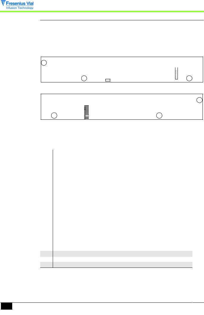
2.1.1 The display board and the front panel
The display board is mounted under the front control panel and is fitted with all the organs required for man-machine interaction.
!Keyboard interface.
!Control lamps and overview diagrams.
!7-segment display units.
 J1
J1
J3
Solder side display board.
J2
Component side display board.
This board is connected to the different parts of equipment by means of connectors.
J1 connector to CPU board
Pin |
Description |
|
1 |
SEG1 display matrix |
Line 1 |
2 |
SEG2 display matrix |
Line 2 |
3 |
SEG3 display matrix |
Line 3 |
4 |
SEG4 display matrix |
Line 4 |
5 |
SEG5 display matrix |
Line 5 |
6 |
SEG6 display matrix |
Line 6 |
7 |
SEG7 display matrix |
Line 7 |
8 |
SEG8 display matrix |
Line 8 |
9 |
COL1 display matrix |
Column 1 |
10 |
COL2 display matrix |
Column 2 |
11 |
COL3 display matrix |
Column 3 |
12 |
FAIL LED control |
Fail |
13 |
COL/DIG 9 LED type control |
" |
14 |
LIG1 keyboard interface |
Line 1 |
15 |
LIG2 keyboard interface |
Line 2 |
16 |
LIG3 keyboard interface |
Line 3 |
17 |
LDSECT lighting control |
Mains LED |
18+5V power supply
19VBAT power supply
20GND power supply
02_008b_en.fm

J2 connector to keyboard
Pin Description
1Column 1
2Column 2
3Column 3
4Column 4
5Column 5
6Column 6
7Line 1
8Line 2
9Line 3
10Ton
11Toff
12Gnd power supply
J3 connector to CPU board
Pin Description
1Ton ON key
2Toff OFF key
3SI SPI bus
4Clk SPI bus
5CSLCD SPI bus
6Buzz BUZZER control
7Vbat power supply
8Gnd power supply
Description and operation
02_008b_en.fm |
13 |
|
|
Description and operation
14
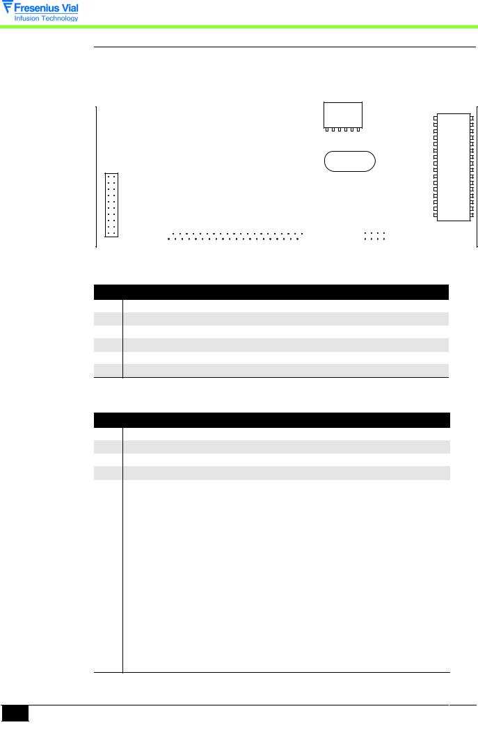
2.1.2 CPU board
The CPU board holds an 80C32 microprocessor. It is mounted and connected to the display board through J4 and J5 connectors.
A ribbon cable connects this to a power supply board by means of a connector J3.
J2
J4
J3 |
|
J5 |
|
|
|
|
|
|
|
|
|||
|
|
|
|
|||
|
|
|
|
|||
|
|
|
|
|||
|
|
|
|
|||
|
|
|
|
|||
|
|
|
|
|||
|
|
|
|
|||
|
|
|
|
|||
|
|
|
|
|
|
|
CPU board
J2 connector: to flanges detection switch and syringe detection opto-electronic sensor
Pin Description
1Ground
2Flanges contact
3Opto anode diode +5V
4Common points between cathode LED , opto 1 and opto 2 transistor emitters.
5Opto 1 transistor collector
6Opto 2 transistor collector
J3 connector to power supply board
Pin Description
1+5V
2Gnd
3+Vbat
4Gnd
5 |
Phase A |
Motor control |
6 |
Phase B |
Motor control |
7 |
Phase C |
Motor control |
8 |
Phase D |
Motor control |
9 |
I signal |
Motor control |
10 |
Boost signal |
Motor control |
11 |
Sopt1 |
Opto rotation motor output |
|
|
|
12 |
Sopt2 |
Opto anti-siphon |
13 |
Apinf |
Nurse call independent of the buzzer |
|
|
signal |
14 |
Cdopt1 |
Opto rotation motor control output |
15 |
Cdopt2 |
Opto anti-siphon module control |
16 |
Off |
Signal off key pressed |
17 |
Sect |
Mains power supply on signal |
|
|
|
18 |
Cdalim |
Power cut signal |
02_008b_en.fm

J3 connector to power supply board
Pin |
Description |
|
19 |
Ldsect |
Mains LED control |
20 |
Cts |
Clear to send |
21 |
Deb/off |
Disengagement signal |
22 |
Rts request to send |
Request to send |
23 |
Occ/off |
Occlusion signal |
24 |
Buz |
Nurse call relay control |
25 |
Eoc |
End Of adc conversion |
26 |
Csadc |
Selection spi adc bus |
27 |
Clk |
Clock spi adc bus |
28 |
Si |
Data in spi adc bus |
29 |
So |
Data out spi adc bus |
30 |
Cdana |
Analogue sensor power supply control |
31 |
Rx2 |
Receive data TTL |
32 |
Tx2 |
Transmit data TTL |
33 |
Txd1 |
Transmit data TTL |
34 |
Rxd1 |
Receive data TTL |
35 |
Ton |
ON key |
36 |
Toff |
OFF key |
37 |
+Vbat |
Power supply |
38Gnd
39+5V
40Gnd
J4 connector to display board
Pin |
Description |
|
1 |
Seg1 display matrix |
Line 1 |
2 |
Seg2 display matrix |
Line 2 |
3 |
Seg3 display matrix |
Line 3 |
4 |
Seg4 display matrix |
Line 4 |
5 |
Seg5 display matrix |
Line 5 |
6 |
Seg6 display matrix |
Line 6 |
7 |
Seg7 display matrix |
Line 7 |
8 |
Seg8 display matrix |
Line 8 |
9 |
Col1 display matrix and keyboard |
Column 1 |
10 |
Col2 display matrix and keyboard |
Column 2 |
11 |
Col3 display matrix and keyboard |
Column 3 |
12Fail diode fail control
13Rdcrt current reduction control
14 |
Lig1 keyboard interface |
Line 1 |
15 |
Lig2 keyboard interface |
Line 2 |
16 |
Lig3 keyboard interface |
Line 3 |
17Ldsect mains LED control
18+5V power supply
19Vbat power supply
20Gnd power supply
02_008b_en.fm |
15 |
|
|
Description and operation

J5 connector to display board
Pin Description
1Ton ON key
2Toff OFF key
3Si spi bus
4Clk spi bus
5Cslcd spi bus
6Buzz buzzer control
7Vbat power supply
8Gnd power supply
Description and operation
|
16 |
02_008b_en.fm |
|
|
|

2.1.3 The power supply board and the battery
The power supply board is mounted on the lower case. It allows to supply the electronic parts using the network 230 V AC or the external 12 / 15 DC. It also charges the 1.1 or 1.3 Ah battery.
|
J6 |
J7 |
J8 |
|
J5 |
J9 |
F2 |
|
J3 |
|||
|
|
||
|
J4 |
J1 |
|
J2 |
F1 |
|
Power supply board.
This board is connected to the different parts of equipment by means of connectors.
J1 connector to mains
Pin Description
1Neutral
2Phase
J2 connector to CPU board
|
Pin |
Description |
|
|
1 |
+5V controlled power supply |
|
|
|
|
2 |
Gnd power supply |
|
|
3 |
+Vbat power supply |
|
|
|
|
4 |
Gnd power supply |
|
|
5 |
Phase A |
Motor control |
||
|
6 |
Phase B |
Motor control |
|
7 |
Phase C |
Motor control |
||
|
8 |
Phase D |
Motor control |
|
9 |
I signal |
Motor control |
||
|
10 |
BOOST signal |
|
|
11 |
Sopt1 |
Opto rotation module output |
||
|
12 |
Sopt2 |
Opto anti-siphon module output |
|
13 |
N.U |
|
|
|
|
14 |
Cdopt1 |
Opto rotation module control |
|
15 |
Cdopt2 |
Opto anti-siphon module control |
||
|
16 |
Off |
Off key pressed on the ON/OFF button |
|
17 |
SECT |
Mains supply presence signal |
||
|
18 |
CDALIM |
Power cut signal |
|
19 |
LDSECT |
Mains LED control |
||
|
20 |
CTS |
Clear to send |
|
21 |
DEB/OFF |
Disengagement signal active at 0 |
||
|
|
|
|
|
02_008b_en.fm |
|
|
17 |
|
|
|
|
|
|
Description and operation

Description and operation
18
J2 connector to CPU board
Pin |
Description |
|
22 |
RTS |
Request to send |
23 |
OCC/OFF |
Occlusion signal active at 0 |
24 |
BUZ |
Nurse call relay control |
25 |
EOC |
End of ADC conversion |
26 |
CSADC |
Selection bus SPI ADC |
27 |
CLK |
Clock bus SPI ADC |
|
|
|
28 |
SI |
Data IN bus SPI ADC |
29 |
SO |
Data out bus SPI ADC |
30 |
CDANA |
Analogue sensor power supply control |
|
|
|
31RX2 receive data TTL
32TX2 transmit data TTL
33TXD1 transmit data TTL
34RXD1 receive data TTL
35 |
Toff |
OFF key |
36 |
Ton |
ON key |
37 |
+Vbat |
Power supply |
38Gnd
39+5V
40Gnd
J3 connector to potentiometer
Pin Description
1Vref
2Centre point
3Gnd
J4 connector to internal battery
Pin Description
1+ battery
2- battery
J5 connector to motor
Pin Description
1+Vbay
2+Vbat
3Phase D
4Phase C
5Phase B
6Phase A
7Opto rotation anode diode /+5V
8Opto rotation cathode diode
9Opto rotation transistor collector
10GND/ opto rotation transistor emitter
02_008b_en.fm

J6 connector to RS232 and Master plugs
Pin Description
1TX1
2+5V
3RX1
4Gnd
5Interface validation
6Nurse call relay common point
7Nurse call relay normally open
8Nurse call relay normally closed
9CD ON external on
10CD OFF external off
11 |
I-OPTON |
Motor control output |
12 |
I-SECT |
Mains led |
13 |
+Vbat |
External power supply plug |
14RX2
15TX2
16Gnd
17CTS
18RTS
19BUZ
20NC
J7 connector to external DC power supply
Pin Description
1± external power supply
2± external power supply
J8 connector to disengagement micro-switch, force sensor and anti-siphon switch
Pin Description
1Not used
2Micro-switch input/output
3Micro-switch input/output
4Not used
5Opto anti-siphon cathode diode
6Opto anti-siphon anode diode/+5V
7Opto anti-siphon transistor collector
8Disengagement micro-switch on
9Disengagement micro-switch off
10Gnd
Do not forget to dismount the ribbon cable holder on the power supply board before extracting the mechanical assembly from the housing (risk of breaking the ribbon cable).
02_008b_en.fm |
19 |
|
|
Description and operation

J9 connector, test points
Pin Description
1GND
2Position sensor output
3Battery discharge control output
4Amplified force sensor output
5Cd coupler power supply 0-5V
6Motor control opto output
7Force and position sensor reference voltage
8Piston head detection opto output
9Control/APIN F
10Control/APIN F
2.1.4 Mechanical gear box unit
The mechanical base unit is composed of a motor-reducer block driving a screw-and-nut unit. At the shaft end, the motor receives a control panel associated with an opto-electronic switch.
The mechanical base unit also accommodates a potentiometer fitted with a rack pinion system.
2.1.5 Mechanical plunger unit
The mechanical plunger unit is mounted onto the mechanical gear box. The gear box ensures the displacement movement of the plunger through a screw / nut system.
The plunger is fitted with a disengagement control allowing to separate this from the screw- and-nut system.
Description and operation
|
20 |
02_008b_en.fm |
|
|
|
2.2 Functional description
From a functional point of view, the Pilot A2 Events Log is composed of three subassemblies:
!A syringe position control and maintenance assembly.
!A motorisation assembly.
!An external connection assembly.
2.2.1 Syringe control and maintenance assembly
The syringe if fitted into the upper case and held in position by means of a syringe clamp.
Detection of the syringe size (60 cc or 20 cc) is carried out by two opto-electronic sensors mounted onto the syringe clamp.
The flanges switch ensures the syringe flanges are correctly positioned in the groove. Associated with an opto-electronic sensor, the anti-siphon arm controls the piston position.
Composed of a micro-switch fitted to the plunger, an anti-occlusion system triggers an alarm whenever force on the piston is excessive.
2.2.2 Motorisation assembly
This sub-assembly moves the piston in the syringe.
It is put into motion by means of a motor-reducer unit associated with a screw-and-nut system.
A motor rotation disk mounted on the shaft end of the motor and associated with an optoelectronic sensor controls the rotation.
A potentiometer controls the plunger movement by means of a rack pinion system.
A micro-switch allows for control of the disengagement device.
2.2.3 External connection sub-assembly
The Pilot A2 Events log has three connectors located at the rear end of the lower case:
!A 12-15 V DC, 15 W type external power supply connector.
!An RS 232 connector.
Description and operation
02_008b_en.fm |
21 |
|
|

Description and operation
|
22 |
02_008b_en.fm |
|
|
|

3 Description of the menus
3.1 Configuration menu of the current operation parameters
The configuration menu enables users to adapt the Pilot to the specific needs of each department. It provides access to the menus allowing for customisation of the parameters associated with current operation modes.
Fresenius Vial recommends users to implement the selected configuration procedures in the presence of a member of its qualified personnel or a member of the technical department.
It is possible to exit the configuration mode at any time by pressing the OFF key.
This menu enables users to:
!PAr1: select the type of flow rate memorisation.
!PAr2: select the syringe selection mode.
!PAr3: modify the maximum flow rates which can be selected using the keyboard.
!PAr4: configure the list of syringes that can be selected.
!PAr5: select the compulsory priming.
!PAr7: select the KVO flow rate.
!PAr9: select the RS232 communication speed.
!PArA: select the empty syringe mode.
!PArb: select the frequency of preventive checks.
!PArC: select the drug display mode.
!PArd: choose whether or not to activate the flanges detection mode.
!PArF: select the Bolus memorisation mode.
!PArG: enter the list of drugs.
!PArJ: choose whether or not to activate the mains disconnection signal.
!PAr0: enter the current date and time.
Description of the menus
03.2_008b_en.fm |
23 |
|
|
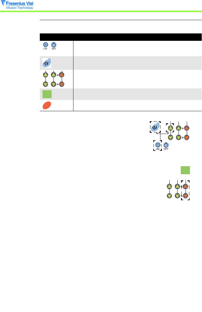
3.1.1 Menu access
Useful keys
Key |
Function |
|
ON, is used to switch the machine ON. |
|
OFF, is used to switch the machine off when pressed for over three |
|
seconds. |
|
SILENCE ALARM, is used to access the configuration mode of the |
|
current operation parameters. |
|
The selection keys allow to scroll the figures and letters on the tenths, |
|
units, tens segments etc. |
OK |
CONFIRM, is used to validate a choice. |
|
|
|
STOP, is used to cancel the current configuration. |
STOP
Switch to configuration mode.
! Press "SILENCE ALARM" and "TENS" simultaneously. ! Maintain this position while pressing "ON".
!When PAr is shown on the display unit, release the selection of "SILENCE ALARM" and "TENS"
then validate within three seconds by pressing "CONFIRM".
!PAr1 is shown by default.
! Switching from PAr1 to PArO is carried out using the "tenths" keys.
OK
Description of the menus
|
24 |
03.2_008b_en.fm |
|
|
|
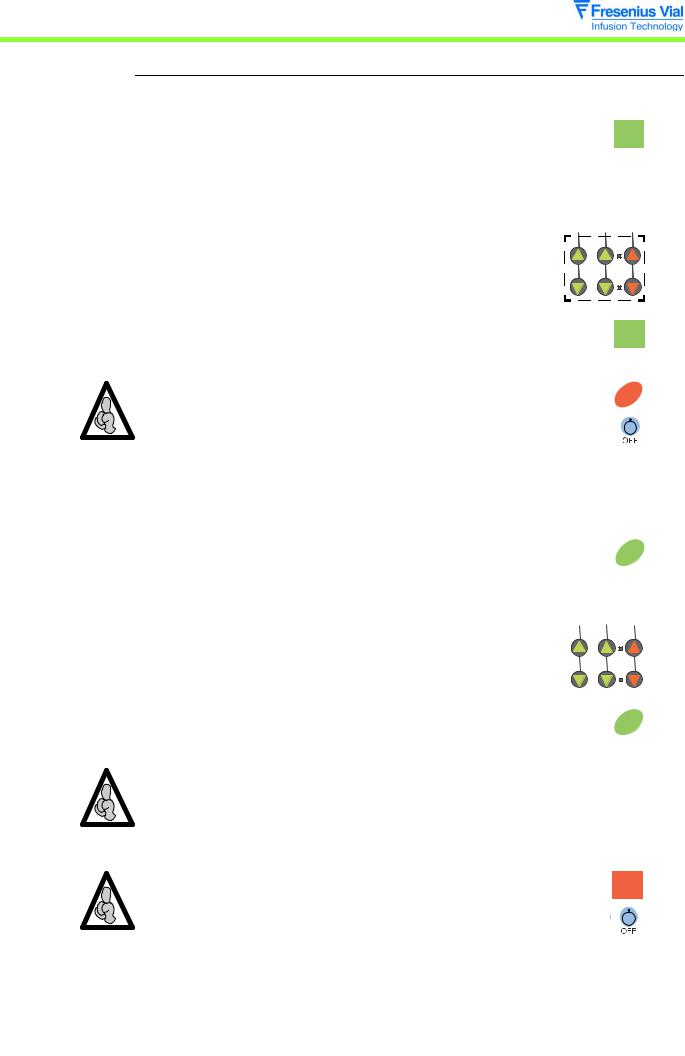
3.1.2 PAr1, configuration of the memorisation type
This configuration enables users to choose whether or not to memorise the infusion flow rate when the Pilot is shut down.
! PAr1, press "CONFIRM" |
OK |
|
"If MEM, the flow rate is memorised when the Pilot is shut down, this value will be displayed by default when the machine is next switched on.
"If noME, the flow rate is not memorised, the default
value is 00.0 each time the machine is switched on.
# Select the memorisation type using the selection keys.
" By validating once again, the type is memorised and it is
possible to select another configuration . |
OK |
|
|
||
The modification may be cancelled by pressing the "STOP" key. |
|
|
STOP |
||
|
||
It is possible to exit the configuration mode at any time by pressing the |
|
|
|
||
"OFF" key. |
|
3.1.3 PAr2, configuration of the syringe selection type |
|
|
|
|
|
|
|
|
|
|
|||
|
|
|
|
|
|
|
|
|
|
|
|
|
|
This configuration enables users to choose the type of syringe selection. |
|
|
|
|
|
|
|
|
|
|
|||
! PAr2, press "CONFIRM" |
|
|
|
|
|
OK |
|||||||
|
|
|
|
|
|
|
|
|
|||||
" If SEL3, automatic validation of the only syringe that |
|
|
|
|
|
|
|
|
|
|
|||
may be selected. |
|
|
|
|
|
|
|
|
|
|
|||
" If SEL4, when the Pilot is switched on, the user should |
|
|
|
|
|
|
|
|
|
|
|||
select the type of syringe installed. |
|
|
|
|
|
|
|
|
|
|
|
|
|
|
|
|
|
|
|
|
|
|
|
|
|
|
|
|
|
|
|
|
|
|
|
|
|
|
|||
# Choose the selection type using the selection keys. |
|
|
|
|
|
|
|
|
|
|
|
|
|
|
|
|
|
|
|
|
|
|
|
|
|||
|
|
|
|
|
|
|
|
|
|
|
|
|
|
|
|
|
|
|
|
|
|
|
|
|
|
|
|
|
|
|
|
|
|
|
|
|
|
|
|
|
|
|
|
|
|
|
|
|
|
|
|
|
|
|
|
|
|
|
|
|
|
|
|
|
|
|
|
|
|
" By validating once again, the type is memorised and it is
possible to select another configuration . |
OK |
When mode SEL3 is selected, and if there is a choice of more than one syringe, the Pilot automatically moves onto the configuration of the list of syringes that may be selected PAr4 when the machine is next switched on.
The modification may be cancelled by pressing the "STOP" key.
STOP
It is possible to exit the configuration mode at any time by pressing the "OFF" key.
03.2_008b_en.fm |
25 |
|
|
Description of the menus
Description of the menus
26
3.1.4 PAr3, configuration of the maximum flow rate that may be selected on the keyboard
This configuration enables users to choose the maximum flow rate that may be selected using |
||||||||||||||||
the keyboard for each type of syringe. |
|
|
|
|
|
|
|
|
|
|
|
|
|
|
||
|
|
|
|
|
|
|
|
|
|
|
|
|
|
|
|
|
Syringe type |
Min. flow rate (ml/hr) |
Max. flow rate (ml/hr) |
|
|||||||||||||
|
|
|
|
|
|
|
|
|
|
|
|
|
|
|
|
|
50/60 cc |
0,1 |
400 |
|
|
|
|
|
|
|
|
|
|
|
|
|
|
|
|
|
|
|
|
|
|
|
|
|
|
|
|
|
|
|
20 cc |
|
0,1 |
275 |
|
|
|
|
|
|
|
|
|
|
|
|
|
|
|
|
|
|
|
|
|
|
|
|
|
|
|
|
|
|
! Par3, press "CONFIRM" |
|
|
|
|
|
|
|
|
|
|
|
|
|
|
||
|
|
|
|
|
|
|
|
|
OK |
|
||||||
" Select the syringe type using the keys. |
|
|
|
|
|
|
|
|
|
|
|
|
|
|
||
|
|
|
|
|
|
|
|
|
|
|
|
|
|
|||
|
|
|
|
|
|
|
|
|
|
|
|
|
|
|||
|
|
|
|
|
|
|
|
|
|
|
|
|
|
|||
|
|
|
|
|
|
|
|
|
|
|
|
|
|
|||
# |
20c, 20 ml. |
|
|
|
|
|
|
|
|
|
|
|
|
|
|
|
|
|
|
|
|
|
|
|
|
|
|
|
|
|
|
||
# |
50c, 50 ml. |
|
|
|
|
|
|
|
|
|
|
|
|
|
|
|
|
|
|
|
|
|
|
|
|
|
|
|
|
|
|
||
|
|
|
|
|
|
|
|
|
|
|
|
|
|
|
||
" Press "CONFIRM" |
|
|
|
|
|
|
|
|
|
|
|
|
|
|
||
|
|
|
|
|
|
|
|
|
|
|
|
|
|
|||
|
|
|
|
|
|
|
|
|
|
OK |
|
|||||
|
|
|
|
|
|
|
|
|
|
|
|
|
|
|
||
# Select the maximum flow rate using the keys. |
|
|
|
|
|
|
|
|
|
|
|
|
|
|
||
" By validating once again, the maximum flow rate is |
|
|
|
|
|
|
|
|
|
|
|
|
|
|
||
|
|
|
|
|
|
|
|
|
|
|
|
|
|
|||
|
|
|
|
|
|
|
|
|
|
|
|
|
|
|||
|
|
|
|
|
|
|
|
|
|
|
|
|
|
|||
|
|
|
|
|
|
|
|
|
|
|
|
|
|
|||
|
|
|
|
|
|
|
|
|
|
|
|
|
|
|||
|
|
|
|
|
|
|
|
|
|
|
|
|
|
|||
|
|
|
|
|
|
|
|
|
|
|
|
|
|
|||
|
|
|
|
|
|
|
|
|
|
|
|
|
|
|||
|
|
|
|
|
|
|
|
|
|
|
|
|
|
|||
|
|
|
|
|
|
|
|
|
|
|
|
|
|
|||
memorised and it is possible to select another |
|
|
|
|
|
|
|
|
|
OK |
||||||
configuration . |
|
|
|
|
|
|
|
|
|
|
||||||
|
|
|
|
|
|
|
|
|
|
|
|
|
|
|
||
The modification may be cancelled by pressing the "STOP" key. |
|
|
||||||||||||||
|
||||||||||||||||
|
|
|
|
|
|
|
|
|
|
|
|
STOP |
|
|||
It is possible to exit the configuration mode at any time by pressing the |
|
|
||||||||||||||
|
||||||||||||||||
"OFF" key. |
|
|
|
|
|
|
|
|
|
|
|
|
|
|
|
|
3.1.5 PAr4, configuration of the list of syringes that may be selected
This configuration enables users to choose whether or not it may be selected for each type of active syringe.
! PAr4, press "CONFIRM" |
OK |
|
|
|
|
"The LED of the syringe to be configured flashes.
#If SEL, this type of syringe may be selected when the Pilot is switched on.
#If noSE, this type of syringe may not be selected
when the Pilot is switched on. " Make your choice using the keys.
|
|
|
|
|
|
|
|
|
|
|
! Press "CONFIRM" to memorise the modification. |
|
|
|
|
||||||
|
OK |
|||||||||
" The LED of the configured syringe is: |
|
|
|
|||||||
|
|
|
||||||||
# |
Lit up is it may be selected. |
|
|
|||||||
# |
Off if it may not be selected. |
|
|
|||||||
03.2_008b_en.fm

Details of the syringe are displayed
when the "tenths" keys are pressed (see chapter 3.1.17 "Typical syringe/details correspondence table").
The modification may be cancelled by pressing the "STOP" key.
STOP
It is possible to exit the configuration mode at any time by pressing the "OFF" key.
3.1.6 PAr5, configuration of the compulsory priming
This configuration enables users to choose whether or not priming is compulsory after selection of a syringe.
! PAr5 is displayed.
" Press "CONFIRM" |
OK |
|
#If PurG, compulsory priming, pressing "BOLUS" during start-up is compulsory to switch to selection of the flow rate.
#If noPu, priming is not compulsory, the flow rate
may be selected upon start-up straight after validation of the syringe.
" Make your choice using the keys.
"By validating once again, the configuration is memorised and it is possible to select another configuration .
The modification may be cancelled by pressing the "STOP" key.
It is possible to exit the configuration mode at any time by pressing the "OFF" key.
OK
STOP
3.1.7 PAr7, configuration of the KVO flow rate
This configuration enables users to choose whether or not to activate the switching to KVO flow rate.
! PAr7, press "CONFIRM" |
OK |
|
|
|
|
"If KVO, KVO flow activated, the infusion continues at 1,0 ml/hr (or at the same flow rate if this is under 1,0 ml/hr) when the volume infused reaches the limit volume.
"If noKV, no KVO flow, infusion stops with a limit volume alarm when the infused volume reaches the limit volume.
"Make your choice using the keys.
|
|
|
|
|
|
|
|
|
|
|
|
|
|
|
|
|
|
|
|
|
|
03.2_008b_en.fm |
27 |
|||||||||
|
|
|
|
|
|
|
|
|
|
|
Description of the menus
Description of the menus
28
" By validating once again, the configuration is memorised
and it is possible to select another configuration . |
OK |
|
|
||
The modification may be cancelled by pressing the "STOP" key. |
|
|
STOP |
||
|
||
It is possible to exit the configuration mode at any time by pressing the |
|
|
|
||
"OFF" key. |
|
3.1.8 PAr9, configuration of the RS232 communication speed
This configuration enables the user to select the communication speed of the RS232 link.
! PAr9, press "CONFIRM" |
OK |
"If 19K2, speed at 19200 Bauds.
"If 19K2, speed at 9600 Bauds.
"If 4800, speed at 4800 Bauds.
" Make your choice using the keys.
" By validating once again, the configuration is memorised
and it is possible to select another configuration . |
OK |
|
The modification may be cancelled by pressing the "STOP" key. |
|
|
STOP |
||
|
||
It is possible to exit the configuration mode at any time by pressing the |
|
|
|
||
"OFF" key. |
|
3.1.9 PArA, configuration of the empty syringe mode
This configuration enables users to choose whether or not to activate using the empty syringe mode.
! PArA, press "CONFIRM" |
OK |
|
"If SVId, empty syringe mode activated.
"If SVId, empty syringe mode deactivated.
" Make your choice using the keys.
" By validating once again, the configuration is memorised
and it is possible to select another configuration . |
OK |
|
|
||
The modification may be cancelled by pressing the "STOP" key. |
|
|
STOP |
||
|
||
It is possible to exit the configuration mode at any time by pressing the |
|
|
|
||
"OFF" key. |
|
03.2_008b_en.fm
3.1.10 PArb, configuration of the frequency of preventive checks
This configuration enables users to select the maintenance frequency which lies between 1 and 9999 hours.
! PArb, press "CONFIRM" |
OK |
|
||||||||||||||
|
|
|
|
|
|
|||||||||||
" The current value is displayed. |
|
|
|
|
|
|
||||||||||
|
|
|
|
|
|
|
|
|
|
|
|
|
|
|
|
|
" Display the new frequency value using the keys. |
|
|
|
|
|
|
|
|
|
|
|
|
|
|
|
|
|
|
|
|
|
|
|
|
|
|
|
|
|
|
|||
|
|
|
|
|
|
|
|
|
|
|
|
|
||||
|
|
|
|
|
|
|
|
|
|
|
|
|
|
|
|
|
|
|
|
|
|
|
|
|
|
|
|
|
|
|
|
|
|
|
|
|
|
|
|
|
|
|
|
|
|
|
|
|
|
|
|
|
|
|
|
|
|
|
|
|
|
|
|
|
|
|
|
|
|
|
|
|
|
|
|
|
|
|||||||
|
|
|
|
|
|
|
|
|||||||||
|
|
|
|
|
|
|
|
|
|
|
|
|
|
|
||
" By validating once again, the new frequency is |
|
|
|
|
|
|
||||||||||
memorised and it is possible to select another |
|
|
|
|
|
|
||||||||||
OK |
|
|||||||||||||||
configuration . |
|
|||||||||||||||
|
|
|
|
|
|
|||||||||||
The modification may be cancelled by pressing the "STOP" key. |
|
|
|
|
|
|
|
|||||||||
|
STOP |
|
||||||||||||||
|
|
|
|
|
|
|
|
|
|
|
|
|||||
It is possible to exit the configuration mode at any time by pressing the "OFF" |
|
|
|
|
|
|
|
|||||||||
|
|
|
|
|
|
|
||||||||||
key. |
|
|
|
|
|
|
||||||||||
3.1.11 PArC, configuration of the drug display mode
This configuration enables users to choose whether or not to display the first four letters of the name of the drug used.
! PArC, press "CONFIRM" |
OK |
|
|
|
|
"If drUG, display activated, after validation of the syringe type, the operator should select the name of the drug used out of the choice of 15 names.
"If nodr, display deactivated, the Pilot does not offer a choice of drug names.
" Make your choice using the keys.
"By validating once again, the configuration is memorised and it is possible to select another configuration .
If The modification may be cancelled by pressing the "STOP" key.
It is possible to exit the configuration mode at any time by pressing the "OFF" key.
OK
STOP
Description of the menus
03.2_008b_en.fm |
29 |
|
|
Description of the menus
30
3.1.12 PArd, configuration of the Flanges detection mode
This configuration enables users to choose whether or not to activate the syringe flanges position check.
! PArd, press "CONFIRM" |
OK |
|
"If AiLE, detection activated, inappropriate positioning of the flanges is signalled by means of an alarm.
"If noAL, no detection, the inappropriate positioning of the flanges is not checked.
" Make your choice using the keys.
" By validating once again, the configuration is memorised
and it is possible to select another configuration . |
OK |
|
|
|
|
The modification may be cancelled by pressing the "STOP" key. |
|
|
STOP |
|
|
|
|
|
It is possible to exit the configuration mode at any time by pressing the "OFF" |
|
|
|
|
|
key. |
|
|
3.1.13 PArF, configuration of the bolus flow memorisation mode
This configuration enables users to select the bolus flow memorisation mode.
! PArF, press "CONFIRM" |
|
OK |
|||||||||||
|
|
|
|
|
|||||||||
" If MEM, bolus memorised, upon start-up of the Pilot, the |
|
|
|
|
|
||||||||
|
|
|
|
|
|||||||||
bolus flow given corresponds to the last selected. |
|
|
|
|
|
||||||||
" Si noME, bolus not memorised, upon start-up of the |
|
|
|
|
|
||||||||
Pilot, the bolus flow given is that defined by default. |
|
|
|
|
|
||||||||
" Make your choice using the keys. |
|
|
|
|
|
|
|
|
|
|
|
|
|
|
|
|
|
|
|
|
|
|
|
|
|
|
|
|
|
|
|
|
|
|
|
|
|
|
|
||
|
|
|
|
|
|
|
|
|
|
|
|||
|
|
|
|
|
|
|
|
|
|
|
|
|
|
|
|
|
|
|
|
|
|
|
|
|
|
|
|
|
|
|
|
|
|
|
|
|
|
|
|
|
|
|
|
|
|
|
|
|
|
|
|
|
|
|
|
|
|
|
|
|
|
|
|
|
|
|
|
|
|
|
|
|
|
|
|
|
|
|
|
|
|
|
|
If the "not memorised" mode is selected, the bolus default value must be defined.
" If the noMEis selected, the 50 cc LED lights up and the
bolus flow is displayed. |
|
|
# |
Using the keys, enter the bolus value to be defined by |
|
|
default for a 50 cc syringe. |
|
# |
Press "CONFIRM" to memorise it |
OK |
|
||
03.2_008b_en.fm
Loading...