


 Loading...
TECHNICAL GUIDE
TECHNICAL
GUIDE
APPLIX SMART
NT 1021 rev A0 "simplifié"

NT 1021 rev A0
1 Overview ........................................................................................................... |
|
5 |
1.1 |
General .................................................................................................... |
5 |
1.2 |
Operation diagram ................................................................................. |
5 |
1.3 |
Precaution for use.................................................................................. |
6 |
1.4 |
Safety features........................................................................................ |
6 |
1.5 |
Technical data ........................................................................................ |
6 |
1.5.1 |
Electrical..................................................................................................................... |
6 |
1.5.2 |
Mechanical ................................................................................................................. |
6 |
1.5.3 |
Conformity, standards ................................................................................................ |
6 |
2 |
Description and operation............................................................................... |
7 |
|
|
2.1 Physical description of the Pump......................................................... |
7 |
|
|
2.1.1 |
The pump ................................................................................................................... |
7 |
|
2.1.2 |
The holder ................................................................................................................ |
11 |
|
2.2 Functional description......................................................................... |
13 |
|
|
2.2.1 |
Subassembly of holding and control of giving set .................................................... |
13 |
|
2.2.2 |
Pumping subassembly ............................................................................................. |
13 |
|
2.2.3 |
Holder subassembly with external connections ....................................................... |
13 |
3 |
Calibration menu |
............................................................................................ |
15 |
4 |
Preventive maintenance ................................................................................ |
17 |
|
|
4.1 Recommendations ............................................................................... |
17 |
|
|
4.2 Maintenance.......................................................................................... |
17 |
|
|
4.3 Checks................................................................................................... |
19 |
|
|
4.3.1 ...................................................................................... |
Access to calibration menu |
19 |
|
4.3.2 ................................................................................................. |
Battery temperature |
20 |
|
4.3.3 ......................................................................................................... |
Battery voltage |
21 |
|
4.3.4 .............................................................................................. |
Mains presence or not |
21 |
|
4.3.5 ............................................................................................................... |
Buzzer test |
22 |
|
4.3.6 ............................................................................................................ |
Door position |
22 |
|
4.3.7 ............................................................................................ |
Optical clamp detection |
22 |
|
4.3.8 ........................................................................................ |
Optical background signal |
23 |
|
4.3.9 ..................................................................................................................... |
Keypad |
23 |
|
4.3.10 .......................................................................................................................... |
LCD |
24 |
|
4.3.11 ........................................................................................................ |
Nurse call relay |
24 |
|
4.3.12 ............................................................................................................. |
Air detection |
24 |
|
4.3.13 ................................................................................................ |
Motor command test |
25 |
|
4.3.14 ......................................................................................................... |
Door alarm test |
25 |
|
4.3.15 ...................................................................................... |
Optical detection alarm test |
25 |
|
4.3.16 ................................................................................................. |
Occlusion alarm test |
26 |
|
4.3.17 ............................................................................................ |
Air detection alarm test |
26 |
|
4.3.18 ....................................................................................... |
Periodic control procedure |
27 |
Applix_Smart_Gb_SimplifiéTDM.fm |
3 |
|
|

|
|
|
|
NT 1021 rev A0 |
|
|
|
|
|
|
4.4 |
Flow rate control .................................................................................. |
29 |
|
|
4.4.1 |
Measurement with scales......................................................................................... |
29 |
|
|
|
4.4.2 Measurement using a test tube................................................................................ |
31 |
|
|
4.5 |
Cleaning and desinfection .................................................................. |
33 |
|
|
4.6 |
Storage.................................................................................................. |
33 |
|
5 |
Diagnosis......................................................................................................... |
|
35 |
|
|
5.1 |
Troubleshooting................................................................................... |
35 |
|
|
5.2 |
Error messages.................................................................................... |
37 |
|
6 |
Intervention procedure................................................................................... |
41 |
||
|
|
N°1, Procedure: Housing ........................................................................... |
43 |
|
|
|
N°2, Procedure: Rechargeable batteries .................................................. |
47 |
|
|
44 |
Applix_Smart_Gb_SimplifiéTDM.fm |
|
|
|

NT 1021 rev A0
1 Overview
1.1 General
The APPLIX Smart is intended exclusively for enteral feeding.
It can be used with both home patients and hospital patients and is a very simple pump to operate.
The pump has a continous feeding administration programme and several functions for patient safety.
1.2 Operation diagram
230 V |
AC Power |
|
Battery |
Power |
|
and load |
|||
suppy |
|
regulation |
||
|
|
management |
||
|
|
|
Bag |
|
|
|
|
|
|
|
|
|
Nurse call |
|
Communication |
|
|
|
Giving |
|
|
|
|
set |
Keyboard |
|
|
|
Clamp |
|
UC |
|
detection |
|
|
|
|
|
|
|
|
memory |
|
|
Buzzer |
|
watch dog |
Motor driving |
|
|
|
|
system |
|
Display |
|
|
|
Motor |
|
|
|
|
gear box |
|
|
Sensor interface |
Rotary or |
|
|
|
|
|
movement |
|
|
|
|
detection |
|
Air in line |
|
Door |
Pumping |
|
and |
|
||
|
|
detection |
||
|
pressure sensor |
system |
||
|
|
|||
|
|
|
Pumping segment |
|
|
|
|
|
Overview |
applix01_01a_Gb.fm |
|
|
|
5 |

NT 1021 rev A0
1.3 Precaution for use
The manufacturer may in no case be held responsible for any medical or any other problem, resulting from a mis-use of the equipment.
Consult the technical guide for further information.
1.4 Safety features
The device has a continuous function inspection system as soon as it is switched ON. Any internal failure or any problem in the operating procedure is detected immediately. Nevertheless, abnormal operation of the equipment with no obvious cause must always be reported to the qualified person in your plant or our After Sales Service.
The Applix Pump is equipped with an internal battery which will supply power for normal operation to the equipment if there is an electrical disturbance in the mains network.
1.5Technical data
1.5.1Electrical
Mains supply: 110-230 V + 10% - 50-60 Hz.
Pump holder output: 7.75 V - 800 mA.
Pump battery mode: 24 h at 125 ml/h.
1.5.2 Mechanical
Pump:
Dimensions H x L x P: 128 x 114 x 43 mm.
Weight: 480 g.
Holder:
Dimensions H x L x P: 146 x 162 x 115 mm.
Weight: 450 g.
1.5.3 Conformity, standards
IEC 601-1 edition 88 + amendment 1 + amendment 2.
IEC 601-1-2 EMC.
IEC 601-1-4 risk analysis.
Protection against electric shock: Protection class II, symbol; type BF, symbol.
Protection against moisture:
Pump: IP34 (splash-protected).
Holder: IP 31 (drip-protected).
Overview
|
6 |
applix01_01a_Gb.fm |
|
|
|
NT 1021 rev A0
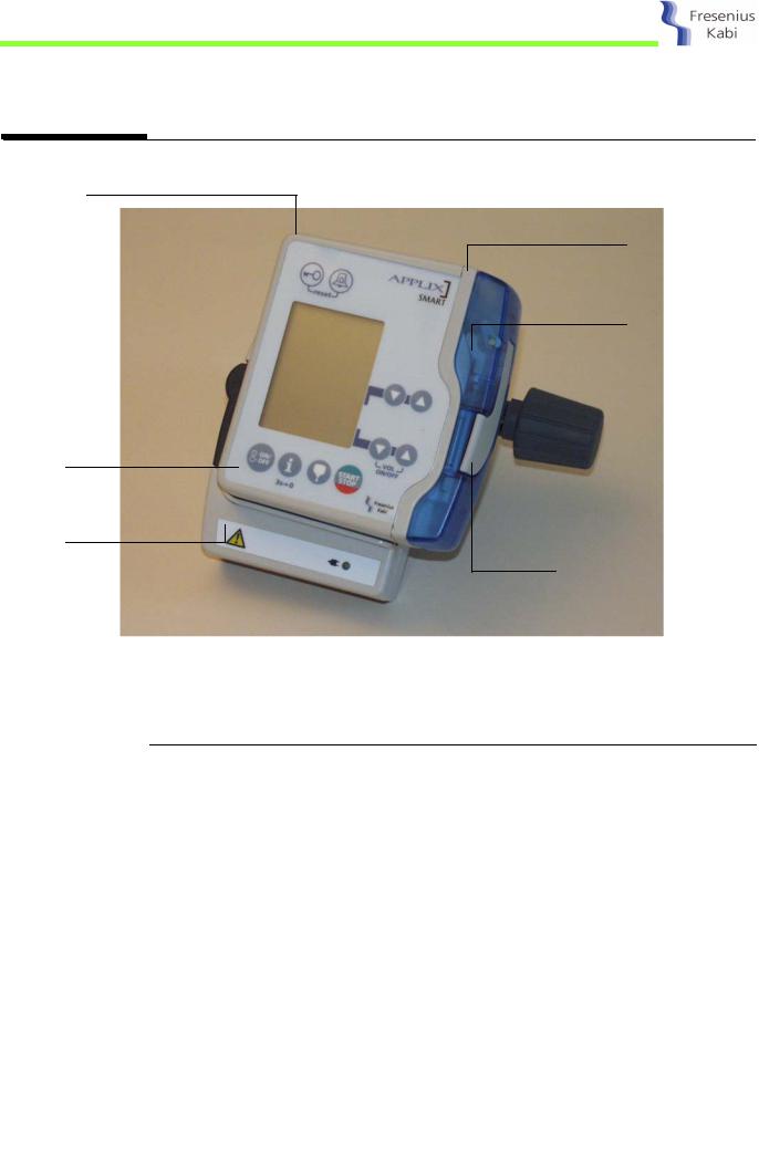
2Description and operation
2.1Physical description of the Pump
Housing
Top surface
Pump door
Keyboard
Holder
Door lever
The APPLIX is composed of a pump which can be mounted on a holder.
2.1.1 The pump
The Pump is composed of a top surface unit holding the mechanical and electronic assembly. A housing fastened on the top surface unit performs mechanical protection and tightness of equipment.
Description and operation
applix02_01a_Gb.fm |
7 |
|
|

Description and operation
8
NT 1021 rev A0
The housing is holding:
A keyboard.
Five contacts for connection of the pump to the holder.
The housing is connected to the different equipment by means of connectors and contacts.
Keyboard connector |
Contacts holder/pump |
||||||
to CPU board |
10 |
||||||
to CPU board |
|
||||||
|
|
||||||
|
1 |
5 |
4 |
3 |
2 |
1 |
|
|
|
|
|
|
|
||
Keyboard connector to CPU board
Pin Description
1ON/OFF
2Column 5
3Column 4
4Column 3
5Column 2
6Column 1
7Line 3
8Line 2
9 |
Line 1 |
10 |
ON/OFF |
Contacts holder/pump to CPU board
Pin Description
1GND
2Alarm command ouput (nurse call)
3Output Txd
4Input Rxd
5Power supply
applix02_01a_Gb.fm

NT 1021 rev A0
The top surface unit is composed of:
A CPU board.
A pumping unit.
A top surface.
The CPU board
The CPU board is holding the power and command electronics for the pump and the LCD screen required for man/machine interface.
|
|
|
J16 |
|
J21 |
|
5 |
2 1 |
|
|
||||
|
Motor |
|||
Optical |
|
1 |
||
|
|
|
|
|
detection |
|
|
|
|
|
|
|
|
|
|
|
|
|
|
|
|
|
|
|
|
|
Battery |
|
|
|
|||
J4 |
|
|
10 |
|
|
|
1 |
4 |
|
|
|
|
|
Keyboard |
|
|
Air detection |
J5 |
|
|
|
Holder |
|||||
|
|
|
|
|
|
||||||||
|
|
|
|
|
|
|
|||||||
|
|
|
1 |
1 |
6 |
|
|
|
|
J6 |
1 |
5 |
|
|
|
|
J17 |
|
|
|
|
|
|||||
|
|
|
|
|
|
|
|
|
|
||||
CPU board
It is connected to the different equipment by means of connectors.
Connector J4, to keyboard
Pin Description
1ON/OFF
2Column 5
3Column 4
4Column 3
5Column 2
6Column 1
7Line 3
8Line 2
9 |
Line 1 |
10 |
ON/OFF |
applix02_01a_Gb.fm |
9 |
|
|
Description and operation

Description and operation
10
NT 1021 rev A0
Connector J5, to battery
Pin Description
1Battery (0 V)
2CTN GND
3CTN (+)
4+ V Bat
Connector J6, to contacts holder
Pin Description
1GND
2Alarm command ouput (nurse call)
3Output Txd
4Input Rxd
5Power supply
Connector J16, to motor
Pin Description
1Motor -
2Motor +
Connector J17, to air detection
Pin Description
1Transmitter (+) anode
2Transmitter (-) cathode
3GND
4GND
5 |
Receiver (+) anode |
6Receiver (-) cathode
Connector J21, to optical board clamp/points valve detection
Pin Description
1GND
2OUT 1 (points valve)
3OUT 2 (Clamp)
4INPUT
5Power supply (V_FCY)
The pumping unit
The pumping unit is fastened on the top surface. It is composed of a frame holding the pumping mechanism, the motor driving system, the electronic board and the battery.
The top surface
The top surface is the interface between the internal and external parts of the pump.
It allows the giving set to be held in the right position and is also holding the door.
applix02_01a_Gb.fm
NT 1021 rev A0
2.1.2 The holder
The holder is composed of a housing equipped with a clamp used to fasten it on a mast.
The holder includes a supply board which supplies 7,75 V AC mains to the APPLIX Pump. It also performs the loading of the 1.2 Ah battery included in the pump.
It is also equipped with:
An RJ45 (RS232) plug for connection of the nurse call relay output or the connection to a PC.
Five contacts for its connection to the pump :
Pin Description
1GND
2Alarm command ouput (nurse call)
3Output Txd
4Input Rxd
5Power supply
1 2 3 4 5
Front view of contacts
Connection of the nurse call alarm output
The nurse call alarm output can be connected by mean of a cable equipped with an RJ45 plug.
Characteristics:
Plug: 8-pin male RJ45.
Length of cable: 2.5 m.
Cable: ref. MJ8 P8C SUNS-PUlow vlt computer.
External connection: 3 tinned wires.
Connection:
Pin Description
1
2
3Link with PC
4
5
6Relay normally open
7Common point
8Relay normally closed
Note:
You can purchase this cable at:
Your Maintenance Department (Address see enclosed)
applix02_01a_Gb.fm
6 7 8
1 8
Plug male RJ45.
Article number ref. 7751761.
11
Description and operation

NT 1021 rev A0
RS232 connection
Characteristics:
Plug: 8-pin male RJ45.
Length of cable: 2.5 m.
Cable: ref. MJ8 P8C SUNS-PUlow vlt computer.
External connection: DB9 femal.
Connection:
Pin RJ45 DB9 femal
13 TxD
27 RTS
34 DTR
42 RxD
55 GND
6
8
7 |
1 |
8 Plug male RJ45.
Note:
You can purchase this cable at:
Your Maintenance Department (Address see enclosed)
Article number ref. 200991.
Description and operation
|
12 |
applix02_01a_Gb.fm |
|
|
|

NT 1021 rev A0
2.2 Functional description
The APPLIX Pump is composed of three functional subassemblies:
A subassembly of holding and control of giving set.
A pumping subassembly.
A holder subassembly with external connections.
2.2.1 Subassembly of holding and control of giving set
The giving set is installed on the top surface and maintained in position by the door.
The top surface is equipped with three detection systems:
A sensor to control the closed door position (UC board).
An optical sensor to detect the type of the installed giving set.
An ultrasonic sensor to detect air bubbles presence in the giving set.
2.2.2 Pumping subassembly
The pumping subassembly includes the peristaltic mechanism of pumping.
This mechanism is composed of a camshaft performing the alternative travel of three pushers. The travel of these pushers, managed by the CPU board, performs the liquid displacement at the flow-rate.
A DC motor with a gear-box subassembly drives in rotation the camshaft by means of an indexed belt.
An optical disc fastened at the camshaft end performs the rotation control.
The occlusion detection is carried out by the measurement of motor current.
2.2.3 Holder subassembly with external connections
The presence of the pump on the holder is detected by a sensor mounted on the holder and associated to a magnet fastened inside the pump.
The holder is equipped with an RJ45 connector used for nurse call alarm or communication with a PC.
Description and operation
applix02_01a_Gb.fm |
13 |
|
|

NT 1021 rev A0
Description and operation
|
14 |
applix02_01a_Gb.fm |
|
|
|

NT 1021 rev A0
3 Calibration menu
The calibration menu is used to perform tests and consult the different parameters recorded in the pump.
The modification of these parameters can only be performed from a PC equipped with the APPLIX control software. The software can be ordered by approved and qualified technicians who have been trained.
For access to the different parameter readout, refer to "Control" chapter.
The calibration menu gives access to twenty-one sub-menus. Only thirteen are necessary for the maintenance technician. Others are not detailed in this guide.
49, not detailed.
50, battery temperature.
51, battery voltage.
52, not detailed.
53, not detailed.
54, not detailed.
97, mains presence or not.
98, buzzer.
100, door position detection.
101, optical clamp detection.
102, not detailed.
103, optical background signal.
107, keypad.
108, LCD.
110, nurse call relay.
112, not detailed.
113, not detailed.
114, air detection .
119, motor command test.
122, not detailed.
Calibration menu
applix03_01a_Gb.fm |
15 |
|
|
Loading...