


bibag® V2.0
Technician’s Manual
Part Number 490188 Rev D
Bibag® V2.0 Technician’s Manual
© Copyright 2012 – 2014 Fresenius Medical Care, Inc.—All Rights Reserved
This document contains proprietary and confidential information of Fresenius USA, Inc. d/b/a Fresenius
Medical Care North America and its affiliates (“Fresenius Medical Care”). The contents of this document may not be disclosed to third parties, copied, or duplicated in any form, in whole or in part, without the prior written permission of Fresenius Medical Care.
Fresenius Medical Care, the triangle logo, 2008, and bibag are trademarks of Fresenius Medical Care Holdings, Inc., and/or its affiliated companies. All other trademarks are the property of their respective owners.
Any questions, contact Technical Support at 800-227-2572
bibag V2.0 Technician’s Manual
TABLE OF CONTENTS
bibag Details ....................................................................................................................... |
2 |
General Warnings ............................................................................................................... |
3 |
Hydraulic Flow Diagram .................................................................................................... |
4 |
Hydraulic Component Descriptions.................................................................................... |
5 |
Hydraulic Operation............................................................................................................ |
8 |
Electronic Description ...................................................................................................... |
10 |
Electronic Block Diagram................................................................................................. |
11 |
Calibrations ....................................................................................................................... |
12 |
Annual Maintenance ......................................................................................................... |
13 |
Debug Screens .................................................................................................................. |
14 |
Troubleshooting ................................................................................................................ |
27 |
Spare Parts ........................................................................................................................ |
28 |
Page 1
bibag V2.0 Technician’s Manual
P/N 490188 Rev. D
bibag Details
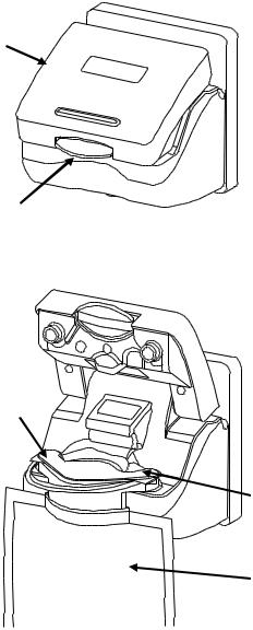
The bibag connector is a hardware option that allows the usage of a dry bicarbonate powder to generate dialysate solution for the 2008®T and the 2008K@HOME™ hemodialysis machines. The bibag is a bag filled with dry bicarbonate powder with special inlet and outlet ports. Underneath the bibag door, the bibag hangs on two nozzles, which allow for the entry of purified water and the exit of bicarbonate concentrate solution. A door handle locks the bibag door in place over the bibag.
bibag door
Door handle
Bicarbonate outlet nozzle
Water inlet nozzle
bibag
Figure 1 – bibag connector: door closed and bibag inserted with door open
Page 2
bibag V2.0 Technician’s Manual
P/N 490188 Rev. D

General Warnings
Warning: The concentrate displayed on the screen must match the labels on the acid container. Make certain there is enough concentrate in the containers to complete the treatment.
Warning: The specific concentrate, sodium, and bicarbonate settings must be prescribed by a physician.
Warning: Acid and basic bicarbonate hemodialysis concentrate must be diluted (mixed with purified water as specified in the AAMI standards for water for dialysis) immediately prior to application only.
Warning: Use aseptic technique.
Warning: Always verify the conductivity and approximate pH of the dialysate solution through independent means before initiating dialysis. Verify that the pH is normal and that the conductivity is reasonably close to the theoretical value. If it is not, do not initiate dialysis.
Warning: Replace a leaking bibag immediately. Spills can cause damage to carpeting and other surfaces. To contain such spills, the machine should be on a spill-tolerant surface. Spills can cause slips and falls; clean up spills immediately.
Caution: Only the bags manufactured by Fresenius Medical Care may be used in the bibag connector.
Note: When the bibag connector is installed, the online pressure holding test becomes mandatory. For more information, see the Online Pressure Holding Test section of the 2008®T Hemodialysis Machine Operator’s Manual P/N 490122 or the 2008K@HOME™ Hemodialysis Machine Operator’s Manual P/N 490180.
Page 3
bibag V2.0 Technician’s Manual
P/N 490188 Rev. D

Hydraulic Flow Diagram
Figure 2
Page 4
bibag V2.0 Technician’s Manual
P/N 490188 Rev. D
Hydraulic Component Descriptions
100 – bibag Fill Valve
The bibag fill valve opens as needed to add water to the bibag during dialysis. When the bibag is not used for bicarbonate during dialysis, this valve will remain closed. In rinse and cleaning modes, this valve will alternate with valve 103.
101 – bibag Vent Valve
The bibag vent valve opens momentarily during bibag dialysis when air is detected in the bibag air separation chamber. When the bibag is not used for bicarbonate during dialysis (jug mode), this valve will open momentarily when air is detected in the bibag air separation chamber.
103 – Hydrochamber Outlet Valve
The hydrochamber outlet valve opens in dialysis when valve 100 is closed. In rinse and cleaning modes, this valve will alternate with valve 100.
104 – Bicarbonate Port Valve
Closed for bibag dialysis. Opens to empty the bibag and during bibag startup. Opens when sodium bicarbonate concentrate is supplied. When sodium bicarbonate is supplied by a pressurized supply, this valve will open and close based on pressure at pressure transducer 110.
105 – Acid Port Valve
Used to regulate the pressure to the acid pump. Will open and closed based upon pressure at pressure transducer 106.
106 – Acid Port Pressure Transducer
Senses pressure of the acid concentrate supply. Pressure detected from this sensor is used in conjunction with valve 105 to regulate the pressure to the acid concentrate pump.
108 – Rinse Port Valve
This valve is electrically in parallel with valve 104. It opens and closes at the same time as valve 104.
110 - bibag Pressure Transducer
The bibag pressure transducer is used to measure the pressure inside the bibag. Also used to measure the pressure of the sodium bicarbonate concentrate source when bibag is not used.
Page 5
bibag V2.0 Technician’s Manual
P/N 490188 Rev. D
Hydraulic Component Descriptions (cont.)
111 – bibag Air Separation Chamber
The bibag air separation chamber separates air from the sodium bicarbonate concentrate upon leaving the bibag. It also is used to separate air from the sodium bicarbonate concentrate supplied by external sources (pre-mixed concentrates).
112 – bibag Air Separation Chamber Air Sensor
The bibag air separation chamber air sensor detects air in the air separation chamber.
113 – bibag Conductivity Cell
The bibag conductivity cell is used to measure the conductivity of the sodium bicarbonate concentrate leaving the bibag and the conductivity of the pre-mixed concentrates.
114 – bibag Temperature Thermistor
The bibag temperature thermistor is used to measure the temperature of the bicarbonate concentrate leaving the bibag and the pre-mixed concentrate.
115 – bibag Present Switch
The bibag present switch is built into the bibag connector. The switch is positioned so that when a bibag is attached to the bibag connector the switch is pressed indicating the presence of a bibag bag.
116 – Bicarbonate Temperature Thermister
Used with conductivity cell 117 to measure conductivity.
117 – Bicarbonate Conductivity Cell
Measures conductivity of the bicarbonate concentrate from the bibag after it is mixed with R.O. water.
118 – bibag Filter
Removes any particles that may enter through the bibag.
Page 6
bibag V2.0 Technician’s Manual
P/N 490188 Rev. D
bibag Connector
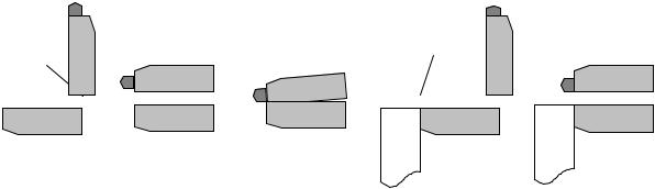
The bibag connector holds the bag with dry bicarbonate during dialysis. The bibag connector incorporates a three position door (see Figure 3). The door may be placed in the position open, operating, or bypass. In the open position (1) and (4), a bibag may be installed or removed from the connector. The operating position (5) is used when a bibag is installed for dialysis. The bypass position (3) is the completely closed position (not possible if a bag is hanging from the connector). The door must be in the closed position
(3) for rinse, cleaning, and jug dialysis mode. Position (2) should not be used.
Door |
|
|
bibag |
|
|
|
|||||||
|
|
|
|
|
|
|
|
|
|||||
|
|
|
|
|
|
|
|
|
|
|
|
|
|
|
|
|
|
|
|
|
|
|
|
|
|
|
|
|
|
|
|
|
|
|
|
|
|
|
|
|
|
|
|
|
|
|
|
|
|
|
|
|
|
|
|
|
|
|
|
|
|
|
|
|
|
|
|
|
|
|
|
|
|
|
|
|
|
|
|
|
|
|
|
|
|
|
|
|
|
|
|
|
|
|
|
|
|
1 |
2 |
3 |
4 |
5 |
Figure 3
Page 7
bibag V2.0 Technician’s Manual
P/N 490188 Rev. D
Hydraulic Operation
Dialysis with bibag
Heated water from chamber E of the hydrochamber flows to the junction of valves 100 and 103. Valve 100 opens and the bibag will start filling when the dialysate temperature at temperature sensor 3 reaches 30 degrees C. Valve 100 will close when the pressure reaches 150mmHg as monitored by the pressure transducer 110. After this initial fill, valves 104 and 108 open, valve 103 closes, the balancing chamber valves open and any excess gas generated in the bag is flushed through the hydraulics down the drain. The flow pump runs and the machine is kept in bypass during this initial flush. Afterwards, additional water will be added to the bag to maintain pressure in the bag of about 90mmHg.
The conductivity cell (113) and temperature sensor (114) measure the conductivity and temperature of the sodium bicarbonate concentrate as it leaves the bag. The temperature compensated conductivity determines the concentration of the sodium bicarbonate concentrate and the delivery rate of the bicarbonate pump (17).
If air is sensed by the probes (112) in the air separation chamber, valve 101 is momentarily opened to vent the air.
If the bibag pressure does not change while the bicarbonate pump is pumping, an airlock condition is detected. To remove the airlocked condition in the bicarbonate pump, valve 100 opens to pressurize the bag to 150mmHg. Next, the flow is stopped, the balance chamber valves are opened up, the flow pump runs, and the machine is kept in bypass.
Conductivity cell 117 checks the amount of sodium bicarbonate added to the dialysate and an error will be displayed if the solution is not within ±5% of expected.
Dialysis with Sodium Bicarbonate Concentrates
Jug bicarbonate dialysis is also supported with the bibag hydraulics. To run in this mode, the bibag connector door must be completely closed and the bicarbonate connector pulled out. Valves 104 and 108 will open and close based on pressure transducer 110 to allow bicarbonate concentrate to reach the bicarbonate pump. Conductivity and temperature of the solution is monitored.
Rinse & Mandatory Rinse
Mandatory rinse is run after a chemical disinfect. Both rinse and mandatory rinse are the same valve sequence for the valves in the bibag hydraulics. Valves 104 and 108 alternate opening every 3 seconds. Valves 100 and 103 alternate opening every 3 seconds. Valve 101 is also opened periodically when conductivity is low. Valve 105 is open.
Page 8
bibag V2.0 Technician’s Manual
P/N 490188 Rev. D
Hydraulic Operation (cont.)
Chemical Disinfection/Rinse
The same bibag valve sequence as in rinse.
Chemical Disinfection/Dwell
The same bibag valve sequence as in rinse
Acid Clean
The bibag valve sequence is the same as chemical rinse. Both concentrate and bicarbonate connectors are plugged into acid.
Heat disinfect
The bibag valve sequence is the same as rinse.
Flow off
Valves 100 and 101 closed. Valve 103 open
bibag Empty
The bibag empty procedure removes the liquid solution from the bag to make disposal of the used bag easier and cleaner. To empty the bag, valves 100, 103 and 105 are closed while the balancing chamber and valves 104 and 108 are opened up. The flow pump runs to suck solution from the bag and send it out the drain. During the emptying process, the hydraulics are kept in bypass. When the empty is complete, the operator is notified, normal balance chamber switching resumes, but the hydraulics remain in bypass until a new bag is installed and correct conductivity of the dialysate returns.
Page 9
bibag V2.0 Technician’s Manual
P/N 490188 Rev. D
Electronic Description
bibag Interface Board
The bibag interface board ‘piggybacks’ onto the actuator - test board and communicates with it. The bibag hydraulic assembly and the bibag distribution box 2 connect electrically to the bibag interface board with ribbon cables.
The bibag interface board contains all of the electronics required to activate the 5 additional valves, read conductivity from the bibag and bicarbonate conductivity cells, read temperature from the bibag and bicarbonate temperature thermistor, read the status of the bibag air sensor, and read the status of the bibag door’s internal switches. A microcontroller on the board controls all of these processes and communicates serially with the actuator - test board. The presence of the communications between the bibag interface board and the actuator - test board indicates to the system the presence of the bibag hydraulic components.
The bibag pressure transducer is automatically calibrated when the door is open, and the value is saved into memory on the bibag interface board.
bibag Hydraulic Assembly – Distribution Board
The bibag hydraulic assembly - distribution board is a passive board that connects to the bibag interface board through a 26 pin cable. All of the individual bibag components on the bibag hydraulic assembly connect electrically to this distribution board.
bibag Distribution Box 2 – Distribution Board
The bibag distribution box 2 - distribution board is a passive board that connects to the bibag interface board through a 20 pin cable. All of the individual bibag components on the distribution box 2 connect electrically to this distribution board.
Page 10
bibag V2.0 Technician’s Manual
P/N 490188 Rev. D
 Loading...