


 Loading...
4008 E / 4008 B / 4008 H / 4008 S
Hemodialysis system
Technical Manual
Edition: 5/03.09 Part no.: M40 618 1
Software 4.5/5.3 and higher
Fresenius Medical Care

Important information on the Technical Manual
How to use the Technical Manual
Identification |
The document can be identified by the following information on the title page and |
|
on the labels, if any: |
|
– Edition of the technical document |
|
– Part number of the technical document |
Page identification |
The page identification 1-3, for example, refers to: chapter 1, page 3. |
Editorial information |
The editorial information 1/01.05, for example, refers to the 1st edition, January |
|
2005. |
Changes |
Changes to the Technical Manual will be released as new editions or supple- |
|
ments. In general: This manual is subject to change without notice. |
Significance of the |
Explanation of the Caution and Note symbols used: |
safety precautions
Caution
Advises the operator against certain procedures or actions that could cause damage to the equipment or may have adverse effects on operators and patients.
Note
Informs the operator that if the steps are not followed as described, a specific function will be executed incorrectly or will not be executed at all, or will not produce the desired effect.
Fresenius Medical Care 4008 5/03.09 (TM) |
0-1 |
Important information on the system
Technician’s qualification
Purpose |
This Technical Manual is intended for service technicians and is to be used for |
|
first studies (to acquire a basic knowledge) and for reference purposes (for TSC, |
|
Maintenance and repair). The Technical Manual, however, does not replace the |
|
training courses offered by the manufacturer. |
Requirements |
Knowledge of the current Operating Instructions for the respective system. |
|
Background experience in mechanics, electrical and medical engineering. |
Precautions for working on the system
Authorized persons |
Assembly, extensions, adjustments, modifications or repairs may only be carried |
|
out by the manufacturer or persons authorized by him. |
Test equipment and |
The activities described in this technical document require the availability of the |
accessories |
necessary technical test equipment and accessories. |
Specifications |
For the specifications of the respective system, refer to the current Operating |
|
Instructions. Observe the information on the specifications. |
Precautions |
Before turning power on, repair any visible damage. |
|
Prior to opening the system and when working on the open system, the following |
|
precautions have to be observed: |
|
– Protect the components against ingress of fluids. |
|
– Do not touch live parts (e.g. connectors of the power cable or heater). |
|
– Disconnect and connect all jacks, connectors and components only when the |
|
system is turned off. |
ESD precautions |
When repairing the system and replacing spare parts, observe the applicable |
|
ESD precautions. |
Hygienic measures |
The system and the consumables are generally considered to be contaminated |
|
and must therefore be sufficiently disinfected by the responsible organization as |
|
specified by the manufacturer. |
0-2 Fresenius Medical Care 4008 5/03.09 (TM)
Addresses
Please address any inquiries to:
Manufacturer |
Fresenius Medical Care AG & Co. KGaA |
|
|
D-61346 Bad Homburg |
|
|
+49 (0)6172-609-0 |
|
|
www.fmc-ag.com |
|
Service |
Fresenius Medical Care |
|
Central Europe |
Deutschland GmbH |
|
|
Geschäftsbereich Zentraleuropa |
|
|
Kundendienst / Servicecenter |
|
|
Steinmühlstraße 24 |
|
|
61352 Bad Homburg |
|
|
Germany |
|
|
Phone: +49 (0)6172-609-7100 |
|
|
Fax: +49 (0)6172-609-7102 |
|
|
E-mail: ServicecenterD@fmc-ag.com |
|
International |
Fresenius Medical Care |
|
service |
Deutschland GmbH |
|
|
Service Support International |
|
|
Hafenstraße 9 |
|
|
D-97424 Schweinfurt |
|
|
Germany |
|
|
Phone: +49 (0)9721-678-333 (hotline) |
|
|
Fax: +49 (0)9721-678-130 |
|
Local service |
|
|
|
|
|
|
|
|
Fresenius Medical Care 4008 5/03.09 (TM) |
0-3 |
0-4 Fresenius Medical Care 4008 5/03.09 (TM)
Table of contents
Section |
|
Page |
1 |
Description of system functions and malfunctions ................................................. |
1- |
1.1 |
Description of the T1 test ............................................................................................... |
1-3 |
1.2 |
Functional description of the modules............................................................................ |
1-78 |
1.3 |
Functional description of the hydraulic unit .................................................................... |
1-83 |
2 |
Technical Safety Checks / Maintenance .................................................................... |
2- |
2.1Technical Safety Checks and Maintenance
|
for 4008 hemodialysis systems and options .................................................................. |
2-3 |
2.2 |
TSC report ...................................................................................................................... |
2-25 |
3 |
Adjustment instructions .............................................................................................. |
3- |
3.1 |
Overview of the DIP switches in the 4008...................................................................... |
3-9 |
3.2 |
Calibration mode ............................................................................................................ |
3-13 |
3.3 |
Hydraulics ....................................................................................................................... |
3-15 |
3.4 |
Air detector ..................................................................................................................... |
3-31 |
4 |
Calibration program ..................................................................................................... |
4- |
5 |
Diagnostics program.................................................................................................... |
5- |
5.1 |
General notes ................................................................................................................. |
5-3 |
5.2 |
Menu structure ................................................................................................................ |
5-5 |
5.3 |
Reading the analog inputs of CPU I ............................................................................... |
5-7 |
5.4 |
Reading the analog inputs of CPU II .............................................................................. |
5-9 |
5.5 |
Reading the digital inputs of CPU I ................................................................................ |
5-10 |
5.6 |
Reading the digital inputs of CPU II ............................................................................... |
5-15 |
5.7 |
Writing the analog outputs of CPU I ............................................................................... |
5-19 |
5.8 |
Writing the analog outputs of CPU II .............................................................................. |
5-20 |
5.9 |
Writing the digital outputs of CPU I ................................................................................ |
5-21 |
5.10 |
Writing the digital outputs of CPU II ............................................................................... |
5-27 |
5.11 |
Writing/Reading the digital outputs of CPU I .................................................................. |
5-30 |
5.12 |
ONLINEplus™ module ..................................................................................................... |
5-31 |
5.13 |
HPU ................................................................................................................................ |
5-32 |
6 |
Setup menu ................................................................................................................... |
6- |
6.1 |
Overview Setup menu settings....................................................................................... |
6-3 |
6.2 |
Overview ......................................................................................................................... |
6-7 |
6.3 |
Main menu 4008 E/B ...................................................................................................... |
6-9 |
6.4 |
Main menu 4008 H/S ...................................................................................................... |
6-37 |
7 |
Miscellaneous ............................................................................................................... |
7- |
Fresenius Medical Care 4008 5/03.09 (TM) |
0-5 |
Section |
|
Page |
8 |
Circuit diagrams and circuit descriptions ................................................................. |
8- |
8.1 |
Block diagram 4008 ........................................................................................................ |
8-3 |
8.2 |
Block diagram of voltage supply .................................................................................... |
8-4 |
8.3 |
Block diagram of screen 4008 H/S ................................................................................. |
8-5 |
8.4 |
Connection layout diagram ............................................................................................. |
8-6 |
8.5 |
P.C.B. LP 450-2 Level detector control (LD) .................................................................. |
8-9 |
8.6 |
P.C.B. LP 493 Blood leak detector ................................................................................. |
8-11 |
8.7 |
P.C.B. LP 624 Control board (BP) .................................................................................. |
8-12 |
8.8 |
P.C.B. LP 630 Motherboard ........................................................................................... |
8-13 |
8.9 |
P.C.B. LP 631 CPU 1 ..................................................................................................... |
8-14 |
8.10 |
P.C.B. LP 632 CPU 2 ..................................................................................................... |
8-16 |
8.11 |
P.C.B. LP 633 Input board ............................................................................................. |
8-18 |
8.12 |
P.C.B. LP 634 Output board ........................................................................................... |
8-20 |
8.13 |
P.C.B. LP 635 Display board .......................................................................................... |
8-22 |
8.14 |
P.C.B. LP 636 External connectors ................................................................................ |
8-24 |
8.15 |
P.C.B. LP 950 Control board (HEP) ............................................................................... |
8-25 |
8.16 |
P.C.B. LP 644-4 Display board (HEP)............................................................................ |
8-26 |
8.17 |
P.C.B. LP 645 Position sensor membrane pump........................................................... |
8-27 |
8.18 |
P.C.B. LP 649-2 Display board (4008 B/S) .................................................................... |
8-28 |
8.19 |
P.C.B. LP 742 Interference filter..................................................................................... |
8-30 |
8.20 |
P.C.B. LP 748 Display board (BP) ................................................................................. |
8-31 |
8.21 |
P.C.B. LP 763 Multi interface board (COMMCO III) ...................................................... |
8-32 |
8.22 |
P.C.B. LP 922 Display board (4008 S) ........................................................................... |
8-33 |
8.23 |
P.C.B. LP 923 Traffic light (4008 H/S) ........................................................................... |
8-34 |
8.24 |
P.C.B. LP 924 Display board (4008 H) .......................................................................... |
8-35 |
8.25 |
P.C.B. LP 941 Hydraulics processor .............................................................................. |
8-36 |
8.26 |
Heater board (power supply unit 4008) .......................................................................... |
8-37 |
8.27 |
Power board (power supply unit 4008) .......................................................................... |
8-38 |
0-6 Fresenius Medical Care 4008 5/03.09 (TM)
Table of contents
1 Description of system functions and malfunctions
Section |
|
Page |
1.1 |
Description of the T1 test ............................................................................................ |
1-3 |
1.1.1 |
T1 test flow diagram, serial program steps .................................................................... |
1-3 |
1.1.2 |
T1 test flow diagram, parallel program steps ................................................................. |
1-5 |
1.1.3 |
Description of the T1 test incl. error messages .............................................................. |
1-7 |
1.1.4 |
Description of system errors during the cleaning programs .......................................... |
1-53 |
1.1.5 |
Error messages after turning power on .......................................................................... |
1-70 |
1.1.6 |
Error messages during dialysis ...................................................................................... |
1-71 |
1.2 |
Functional description of the modules ...................................................................... |
1-78 |
1.2.1 |
Blood pump (arterial) ...................................................................................................... |
1-78 |
1.2.2 |
Blood pump (Single-Needle), optional ........................................................................... |
1-79 |
1.2.3 |
Heparin pump ................................................................................................................. |
1-80 |
1.2.4 |
Air detector ..................................................................................................................... |
1-82 |
1.3 |
Functional description of the hydraulic unit ............................................................. |
1-83 |
|
Fig.: Flow diagram .......................................................................................................... |
1-83 |
1.3.1 |
Description of the hydraulic unit ..................................................................................... |
1-85 |
1.3.2 |
Theory of operation of the balancing chamber .............................................................. |
1-87 |
1.3.3 |
Central delivery system option ....................................................................................... |
1-91 |
1.3.4 |
Program sequences during the cleaning programs ....................................................... |
1-92 |
|
Fig.: Flow chart of cleaning programs – overview .......................................................... |
1-92 |
Fresenius Medical Care 4008 5/03.09 (TM) |
1-1 |
1-2 Fresenius Medical Care 4008 5/03.09 (TM)
1.1Description of the T1 test
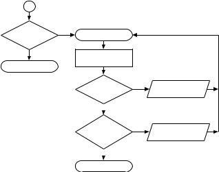
1.1.1T1 test flow diagram, serial program steps
MODULE |
|
|
TEST |
|
|
T1 |
|
|
ACCUMULATOR |
|
|
START T1 TEST |
|
|
TEST OK |
no |
STORAGE |
|
|
|
|||
|
|
|
? |
|
ERROR NUMBER |
|
|
|
yes |
|
|
TEST |
|
|
TEST |
|
|
BYPASS |
|
|
BLOOD LEAK DETECTOR |
|
|
TEST OK |
no |
STORAGE |
TEST OK |
no |
STORAGE |
? |
|
ERROR NUMBER |
? |
|
ERROR NUMBER |
yes |
|
|
yes |
|
|
TEST |
|
|
TEST |
|
|
OPT. DETECTOR |
|
|
TEMPERATURE |
|
|
TEST OK |
no |
STORAGE |
TEST OK |
no |
STORAGE |
? |
|
ERROR NUMBER |
? |
|
ERROR NUMBER |
yes |
|
|
yes |
|
|
TEST |
|
|
NEG. PRESSURE |
|
|
BLOOD SYSTEM |
|
|
HOLDING TEST |
|
|
TEST OK |
no |
STORAGE |
TEST OK |
no |
STORAGE |
? |
|
ERROR NUMBER |
? |
|
ERROR NUMBER |
yes |
|
|
yes |
|
|
TEST |
|
|
POS. PRESSURE |
|
|
VENOUS PRESSURE |
|
|
HOLDING TEST |
|
|
TEST OK |
no |
STORAGE |
TEST OK |
no |
STORAGE |
? |
|
ERROR NUMBER |
? |
|
ERROR NUMBER |
yes |
|
|
yes |
|
|
TEST |
|
|
TEST |
|
|
AIR DETECTOR |
|
|
UF-FUNCTION |
|
|
TEST OK |
no |
STORAGE |
TEST OK |
no |
STORAGE |
? |
|
ERROR NUMBER |
? |
|
ERROR NUMBER |
yes |
|
|
yes |
|
|
TEST |
|
|
TEST |
|
|
DISPLAY |
|
|
CONDUCTIVITY |
|
|
TEST OK |
no |
STORAGE |
TEST OK |
no |
STORAGE |
? |
|
ERROR NUMBER |
? |
|
ERROR NUMBER |
yes |
|
|
yes |
|
|
TEST |
|
|
Basic hydraulics |
|
Advanced hydraulics |
ARTERIAL PRESSURE |
|
|
|
||
|
|
TEST |
|
TEST DIASAFE PLUS / |
|
|
|
|
|
||
|
|
|
DIASAFE/HDF FILTER |
|
ONLINE PLUS / |
|
|
|
|
|
HPU TEST |
TEST OK |
no |
STORAGE |
|
|
|
? |
|
ERROR NUMBER |
|
|
|
yes |
|
|
TEST OK |
no |
STORAGE |
|
|
? |
|
ERROR NUMBER |
|
|
|
|
|
||
|
|
|
yes |
|
|
|
|
|
1 |
|
|
Fresenius Medical Care 4008 5/03.09 (TM) |
1-3 |
1 |
|
T1 TEST |
yes |
UNSUCCESSFUL |
DIALYSIS START KEY |
|
no
INCORRECT
TEST STEP
RETURN
TEST OK |
no |
ERROR |
||
? |
|
DISPLAY |
||
|
yes |
|
|
|
|
|
|
||
FURTHER |
yes |
NEXT INCORRECT |
||
INCORRECT |
||||
|
TEST STEP |
|||
TEST STEPS |
|
|||
|
|
|||
|
no |
|
|
|
|
|
|
||
RETURN |
|
|
||
1-4 Fresenius Medical Care 4008 5/03.09 (TM)

1.1.2T1 test flow diagram, parallel program steps
MODULE
T1
START T1 TEST
TEST |
|
|
TEST |
|
TEST |
|
|
TEST |
|
|
TEST |
|
|
TEST |
|
|
|||||||
OPT. DETECTOR |
|
|
BLOOD SYSTEM |
|
BYPASS |
|
|
DISPLAY |
|
|
ACCUMULATOR |
|
|
ARTERIAL PRESSURE |
|
|
|||||||
|
|
|
|
|
|
|
|
|
|
|
|
|
|
|
|
|
|
|
|
|
|
|
|
|
|
yes |
|
|
yes |
|
|
|
yes |
|
|
yes |
|
|
yes |
|
|
yes |
|||||
TEST OK |
TEST OK |
TEST OK |
TEST OK |
TEST OK |
TEST OK |
||||||||||||||||||
? |
1 |
? |
|
? |
|
|
|
? |
1 |
? |
1 |
? |
1 |
||||||||||
|
no |
|
no |
|
|
no |
|
|
|
no |
|
no |
|
no |
|||||||||
|
|
|
|
||||||||||||||||||||
STORAGE |
|
|
STORAGE |
|
STORAGE |
|
|
STORAGE |
|
|
STORAGE |
|
|
STORAGE |
|
|
|||||||
|
|
|
|
|
|
|
|
|
|
|
|||||||||||||
ERROR NUMBER |
|
|
ERROR NUMBER |
|
ERROR NUMBER |
|
|
ERROR NUMBER |
|
|
ERROR NUMBER |
|
|
ERROR NUMBER |
|
|
|||||||
|
|
|
|
|
|
|
|
|
|
|
|
|
|
|
|
|
|
|
|
|
|
|
|
|
|
|
|
|
|
|
|
|
|
|
|
|
|
|
|
|
|
|
|
|
|
|
|
|
|
|
|
|
|
|
|
|
|
|
|
|
|
|
|
|
|
|
|
|
|
|
|
|
|
|
|
|
|
|
|
|
|
|
|
|
|
|
|
|
|
|
|
|
|||
|
|
|
|
TEST |
|
TEST |
|
|
|
|
|
|
|
|
|
|
|
|
|
|
|||
|
|
|
|
VENOUS PRESSURE |
|
TEMPERATURE |
|
|
|
|
|
|
|
|
|
|
|
|
|
|
|||
|
|
|
|
|
yes |
|
yes |
|
|
|
|
|
|
|
|
|
|
|
|
||||
|
|
|
|
|
|
|
|
|
|
|
|
|
|
|
|
|
|
|
|||||
|
|
|
|
TEST OK |
TEST OK |
|
|
|
|
|
|
|
|
|
|
|
|
||||||
??
|
|
|
|
no |
|
|
|
|
|
no |
|
|
|
|
|
|
|
|
|
|
|||
|
STORAGE |
|
|
|
|
STORAGE |
|
|
|
|
|
|
|
|
|
|
|||||||
|
ERROR NUMBER |
ERROR NUMBER |
|
|
|
|
|
|
|
|
|
|
|||||||||||
|
|
|
|
|
|
|
|
|
|
|
|
|
|
|
|
|
|
|
|
|
|
|
|
|
|
|
|
|
|
|
|
|
|
|
|
|
|
|
|
|
|
|
|
|
|
|
|
|
|
|
|
|
|
|
|
|
|
|
|
|
|
|
|
|
|
|
|
|
|
|
|
|
|
|
|
|
|
|
|
|
|
|
|
|
|
|
|
|
|
|
|
|
|
|
|
|
|
TEST |
|
|
|
|
NEG. PRESSURE |
|
|
|
TEST |
|
|
|
|
|
|||||||
|
AIR DETECTOR |
|
|
|
|
HOLDING TEST |
|
|
|
BLOOD LEAK DETECTOR |
|
|
|
|
|||||||||
|
|
|
|
|
|
|
|
|
|
|
|
|
|
|
|
|
|
|
|
|
|
||
|
|
|
|
|
|
|
yes |
|
|
|
|
yes |
|
|
|
yes |
|
|
|||||
|
TEST OK |
|
TEST OK |
|
TEST OK |
|
|
|
|||||||||||||||
|
|
? |
|
|
|
|
|
|
? |
|
|
|
|
? |
|
|
|
|
|
||||
|
|
|
|
no |
1 |
|
|
no |
|
|
|
|
no |
1 |
|
|
|
||||||
|
|
|
|
|
|
|
|
|
|||||||||||||||
|
STORAGE |
|
|
|
|
STORAGE |
|
|
|
STORAGE |
|
|
|
|
|
||||||||
|
|
|
|
|
|
|
|
|
|
|
|
|
|||||||||||
|
ERROR NUMBER |
|
|
ERROR NUMBER |
|
|
|
ERROR NUMBER |
|
|
|
||||||||||||
|
|
|
|
|
|
|
|
|
|
|
|
|
|
|
|
|
|
|
|
|
|
|
|
|
|
|
|
|
|
|
|
|
|
|
|
|
|
|
|
|
|
|
|
|
|
|
|
POS. PRESSURE |
|
|
|
|
|
|
no |
|
|
|
|
yes |
|
|
TEST |
|
|
||||||
|
|
|
|
|
|
Conductivity? |
|
|
|
|
|
||||||||||||
HOLDING TEST |
|
|
|
|
|
|
|
|
|
|
|
|
|
CONDUCTIVITY |
|
|
|||||||
|
|
|
|
|
|
|
|
|
|
|
|
|
|
|
|
|
|
||||||
TEST OK |
|
|
yes |
|
|
|
|
|
|
|
|
|
|
|
|
TEST OK |
yes |
||||||
? |
|
|
|
|
|
|
|
|
|
|
|
|
|
|
|
|
|
? |
no |
|
|
||
|
no |
|
|
|
|
|
|
|
|
|
|
|
|
|
|
|
|
|
|
|
|
|
|
STORAGE |
|
|
|
|
|
|
|
|
|
|
|
|
|
|
|
|
|
STORAGE |
|
|
|||
ERROR NUMBER |
|
|
|
|
|
|
|
|
|
|
|
|
|
|
|
|
ERROR NUMBER |
|
|
||||
|
|
|
|
|
|
|
|
|
|
|
|
|
|
|
|
|
|
|
|
||||
|
|
|
|
|
|
|
|
|
|
|
|
|
|
|
|
|
|
|
|
|
|||
|
|
|
|
|
|
|
|
|
|
|
|
|
|
|
|
|
|
|
|
|
|
|
|
|
|
|
|
|
|
|
|
|
|
|
|
|
|
|
|
|
|
|
|
||||
TEST |
|
|
|
|
|
|
TEST |
|
|
|
|
|
|
|
POS. PRESSURE |
|
|
||||||
CONDUCTIVITY |
|
|
|
|
|
UF-FUNCTION |
|
|
|
|
|
HOLDING TEST |
|
|
|||||||||
|
|
|
|
|
|
|
|
|
|
|
|
|
|
|
|
|
|
|
|
|
|
|
|
|
|
|
|
|
|
|
|
|
|
|
|
|
|
|
|
|
|
|
|
|
|
|
|
TEST OK |
yes |
TEST OK |
yes |
TEST OK |
yes |
? |
|
? |
|
? |
|
no |
|
no |
|
no |
|
STORAGE |
|
STORAGE |
|
STORAGE |
|
ERROR NUMBER |
|
ERROR NUMBER |
|
ERROR NUMBER |
|
|
|
|
|
|
|
|
Basic hydraulics |
|
|
Advanced hydraulics |
||||
TEST |
|
TEST |
|
|
TEST |
|
|
TEST DIASAFE PLUS / |
||||||
DIASAFE/HDF FILTER |
|
|
|
|
|
|||||||||
|
UF-FUNCTION |
|
|
DIASAFE/HDF FILTER |
|
|
ONLINE PLUS / |
|||||||
|
|
|
|
|
|
|
||||||||
|
|
yes |
|
|
|
|
|
|
|
HPU-TEST |
||||
TEST OK |
|
|
|
|
|
|||||||||
|
|
|
|
|
|
|
|
|
|
|||||
|
|
|
|
|
|
|
|
|
|
|||||
? |
|
TEST OK |
yes |
TEST OK |
yes |
|||||||||
|
|
|
||||||||||||
|
no |
? |
|
|
? |
|
|
|
|
|
|
|||
|
1 |
no |
1 |
|
no |
1 |
|
|
|
|||||
STORAGE |
|
|
|
|
|
|
||||||||
|
|
|
|
|
|
|
|
|
|
|
|
|
||
ERROR NUMBER |
|
STORAGE |
|
|
STORAGE |
|
|
|
|
|
||||
|
|
|
|
|
|
|
|
|||||||
|
|
|
|
|
|
|
|
|
|
|||||
|
|
|
ERROR NUMBER |
|
|
ERROR NUMBER |
|
|
|
|
|
|||
|
|
|
|
|
|
|
|
|
|
|
|
|
|
|
|
|
|
|
|
|
|
|
|
|
|
|
|
|
|
Fresenius Medical Care 4008 5/03.09 (TM) |
1-5 |

1 |
|
|
|
|
|
|
|
|
|
|
|
|
|
|
|
|
|
T1 TEST |
yes |
|
|
||
UNSUCCESSFUL |
DIALYSIS START KEY |
|
|
||
|
no |
INCORRECT |
|
|
|
|
|
|
|||
RETURN |
TEST STEP |
|
|
||
|
|
|
|
||
|
|
TEST OK |
no |
ERROR |
|
|
|
? |
|
DISPLAY |
|
|
|
|
yes |
|
|
|
|
|
|
|
|
|
|
FURTHER |
no |
NEXT INCORRECT |
|
|
|
INCORRECT |
|||
|
|
|
TEST STEP |
||
|
|
TEST STEPS |
|
||
|
|
|
|
||
|
|
|
yes |
|
|
|
|
|
|
|
|
|
|
RETURN |
|
|
|
1-6 Fresenius Medical Care 4008 5/03.09 (TM)
1.1.3Description of the T1 test incl. error messages
● Prerequisites for starting and running the test
Error message |
Description |
Power failure |
Power failure while the test is in progress |
Dialines not conn |
The dialysate lines are not in the interlock shunt. |
Shunt Cover open |
The interlock shunt is open. |
Connect Conc.Line |
|
Wrong conc. supply |
The concentrate connector is in the rinse chamber, or concen- |
|
trate is not connected at all. The error message depends on the |
|
central delivery system preselected in the setup menu. |
Blood Sensed by OD |
The optical detector senses blood in the system. |
Flow alarm |
Line to or from the dialyzer kinked, malfunctions in the hydraul- |
|
ics. |
Water alarm |
Water supply interrupted. |
XXX not calibrated |
A valid calibration value is missing in the NOVRAM. |
● Overview of the individual test steps |
|
Bypass test ..................................................................................................................... |
1-8 |
Optical detector test ....................................................................................................... |
1-10 |
Blood system test ........................................................................................................... |
1-12 |
Venous pressure system test ......................................................................................... |
1-16 |
Air detector test .............................................................................................................. |
1-18 |
Display test ..................................................................................................................... |
1-22 |
Arterial pressure system test .......................................................................................... |
1-24 |
Battery test ..................................................................................................................... |
1-26 |
Blood leak test ................................................................................................................ |
1-28 |
Temperature test ............................................................................................................ |
1-30 |
Negative pressure holding test ....................................................................................... |
1-32 |
Positive pressure holding test ........................................................................................ |
1-34 |
UF function test .............................................................................................................. |
1-39 |
Conductivity test ............................................................................................................. |
1-42 |
Diasafe/HDF filter test .................................................................................................... |
1-44 |
Online plus / Diasafe plus filter / HPU test ..................................................................... |
1-48 |
Fresenius Medical Care 4008 5/03.09 (TM) |
1-7 |

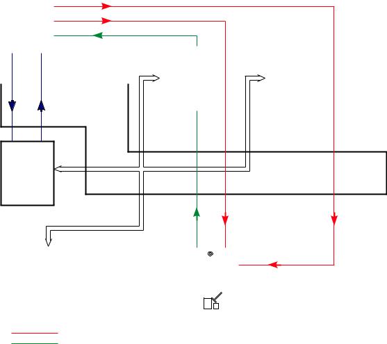
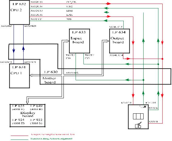
●Bypass test Test description:
Check of the following functions:
–Heater relay
–Bypass (electric)
–Check of the temperature range changeover
Illustration:
X632/A26 HOT_RINSE
|
|
|
|
|
|
|
|
|
|
|
|
LP 639 |
|
|
||
|
|
|
|
|
|
|
|
|
|
|
|
(4008E/H) |
|
|
||
|
|
|
|
|
|
|
|
|
|
|
|
Power |
|
X639/ |
||
|
|
|
|
|
|
|
|
|
|
|
|
|
A20 |
|||
|
|
|
|
|
|
|
|
|
|
|
|
Logic |
|
|
||
|
|
|
X632/A10 |
|
|
H_REL_W |
X639/A12 |
|
LP 647 |
|
|
|||||
|
|
|
X632/A9 |
|
|
EM_H_OFF |
X639/A17 |
|
|
|
||||||
|
|
|
X632/C25 |
|
|
V24_EN |
|
|
(4008S/B) |
|
|
|||||
|
|
|
|
|
|
|
|
|
|
|||||||
|
|
|
|
|
|
|
|
|
|
|||||||
|
|
|
X632/C26 |
|
|
V24B_EN |
|
|
|
|
|
|
|
|||
|
|
|
X632/B22 |
|
|
CI |
|
|
|
|
|
|
|
|||
|
LP 632 |
|
|
|
|
|
|
|
|
|||||||
|
|
X632/A6 |
V26 |
|
|
|
|
|
|
|
||||||
|
CPU 2 |
|
|
|
|
|
|
|
|
|||||||
|
|
|
|
|
|
|
|
|
|
|
|
|
|
|
|
|
|
|
X632/A6 |
|
|
V26 |
|
|
|
|
|
|
|
||||
|
|
|
|
X634R/ |
|
|
|
|||||||||
|
|
|
X632/A5 |
|
|
V24B |
|
X634R/ |
||||||||
|
|
|
X632/A4 |
V24 |
|
A18 |
C22 |
|
||||||||
|
|
|
|
|
|
|
|
|
|
|||||||
|
|
|
|
|
|
|
|
|
|
|
|
LP 634 |
|
|||
X632/B27 |
X632/B28 |
|
|
|
|
|||||||||||
|
|
|
|
|
|
|
|
|
LP 633 |
|
|
Output |
X634R/ |
|||
|
|
|
|
|
|
|
|
|
Input |
X634R/ |
|
|||||
|
|
|
|
|
|
|
|
|
A23 |
|
board |
C24 |
||||
board
X631/A20 |
X631/A21 |
X634L/A25 |
X634L/C12 |
X634L/C25 |
LP 631 |
|
|||
|
|
|
|
|
CPU 1 |
LP 630 |
DATA BUS |
|
|
|
|
|
|
|
|
Mother |
|
|
|
|
board |
|
|
|
LP 635 |
LP 649 |
||
(4008 |
E) |
(4008 |
B) |
|
Display |
|
|
|
board |
|
|
LP 924 |
LP 922 |
||
(4008 |
H) |
(4008 |
S) |
|
|
|
|
Testgenerierung/Generation of Test
Rueckmeldung/Acknowledgement
V24
V24
V24B
V24B
V26
V26
1-8 Fresenius Medical Care 4008 5/03.09 (TM)
Error description: |
|
Error message |
Description |
F 01 Bypass |
The heater relay is switched off. |
|
– Acknowledgement (H_REL_W, X639/A12) → X632/A10, 0 V are |
|
missing. |
F 02 Bypass |
The heater relay cannot be switched off by CPU2. |
|
– Acknowledgement (H_REL_W, X639/Y12) → X632/A10, 12 V are |
|
missing. |
|
– Control line (EM_H_OFF, X632/A9) → X639/A17, 12 V are missing. |
F 03 Bypass |
The temperature measurement range is set to hot rinse. |
|
– Control line (HOTRINSE, X634R/C24) → X639/A20, 0 V are miss- |
|
ing. |
|
– Acknowledgement (HOTRINSE, X634R/C24) → X632/A26, 0 V are |
|
missing. |
F 04 Bypass |
The extended bypass cannot be correctly switched by CPU2 (V24 = off, |
|
V26 = on, V24B = off). |
|
– Acknowledgement (V24, X637/C1) → X632/A4, 24 V are missing. |
|
– Acknowledgement (V26, X637/C2) → X632/A6, 0 V are missing. |
|
– Acknowledgement (V24B, X637/C23) → X632/A5, 24 V are miss- |
|
ing. |
F 05 Bypass |
The extended bypass cannot be correctly switched off by CPU2 (V24 = |
|
on, V26 = off, V24B = on). |
|
– Acknowledgement (V24, X637/C1) → X632/A4, 0 V are missing. |
|
– Acknowledgement (V26, X637/C2) → X632/A6, 24 V are missing. |
|
– Acknowledgement (V24B, X637/C23) → X632/A5, 0 V are missing. |
F06 Bypass |
CPU1 fails to set the temperature control to hot rinse. |
|
– Control line (HOTRINSE, X634R/C24) → X639/A20, 12 V are miss- |
|
ing. |
|
– Acknowledgement (HOTRINSE, X634R/C24) → X632/A26, 12 V |
|
are missing. |
F 07 Bypass |
The extended bypass cannot be correctly switched by CPU1 (V24 = off, |
|
V26 = on, V24B = off). |
|
– Acknowledgement (V24, X637/C1) → X632/A4, 24 V are missing. |
|
– Acknowledgement (V26, X637/C2) → X632/A6, 0 V are missing. |
|
– Acknowledgement (V24B, X637/C23) → X632/A5, 24 V are miss- |
|
ing. |
F08 Bypass |
CPU1 fails to reset the temperature control to dialysis. |
|
– Control line (HOTRINSE, X634R/C24) → X639/A20, 0 V are miss- |
|
ing. |
|
– Acknowledgement (HOTRINSE, X634R/C24) → X632/A26, 0 V are |
|
missing. |
F09 Bypass |
The extended bypass cannot be correctly switched off by CPU1 (V24 = |
|
on, V26 = off, V24B = on). |
|
– Acknowledgement (V24, X637/C1) → X632/A4, 0 V are missing. |
|
– Acknowledgement (V26, X637/C2) → X632/A6, 24 V are missing. |
|
– Acknowledgement (V24B, X637/C23) → X632/A5, 0 V are missing. |
F95 Bypass |
System error |
Fresenius Medical Care 4008 5/03.09 (TM) |
1-9 |
●Optical detector test Test description:
Attenuation of the optical detector.
Check of the acknowledgement of the optical detector.
Illustration:
|
|
LP 632 |
X632/C16 |
|
|
|
LDSA |
|
|
|||
|
CPU 2 |
X632/C15 |
|
|
|
ODSA |
|
|
||||
|
|
|
X632/A30 |
|
|
OD_OUT |
|
|
||||
|
|
|
|
|
|
|
|
|
X633L/C7 |
|
|
|
|
|
|
|
|
|
|
|
|
|
|
||
|
|
|
|
|
|
|
|
|
|
|
|
|
|
|
|
|
|
|
|
|
|
LP 633 |
|
LP 634 |
|
/B27 |
X632/B28 |
|||||||||||
|
|
|
|
|
|
|
||||||
|
|
|
|
|
|
|
|
|
Input |
|
Output |
|
|
|
|
|
|
|
|
|
|
board |
|
board |
|
|
|
|
|
|
|
|
|
|
|
|
|
|
|
|
X633L/C8 |
/A20 |
X631/A21 |
IN |
LP 631 |
OD |
|
|
||
CPU 1 |
LP 630 |
DATA BUS |
|
|
|
|
Mother |
|
|
board |
|
|
|
|
|
X351/5 |
X351/7 |
|||||
LP 635 |
LP 649 |
|
Pven |
|
|
|||||
(4008 |
E) |
(4008 |
B) |
|
|
X351/10 |
||||
|
|
|
|
|
|
|||||
|
Display |
|
|
|
|
|
|
|
|
|
|
board |
|
|
|
|
|
|
|
|
|
LP 924 |
LP 922 |
|
|
|
|
|
|
|
||
|
|
|
|
|
|
|
||||
(4008 |
H) |
(4008 |
S) |
|
|
|
|
|
|
|
|
|
|
|
|
|
|
|
|
|
|
|
|
|
|
|
|
|
|
|
|
|
Testgenerierung/Generation of Test
Rueckmeldung/Acknowledgement
1-10 |
Fresenius Medical Care 4008 5/03.09 (TM) |
Error description: |
|
|
Error message |
Description |
|
F01 opt. Detector |
CPU1 interprets the optical detector in a different way than does CPU2. |
|
|
– |
Acknowledgement (OD_OUT, X633L/C7) → X632/A30 and the |
|
|
digital input of P.C.B. LP 633 measure different levels. |
F02 opt. Detector |
CPU2 fails to recognize blood in the system. |
|
|
– |
Acknowledgement (OD_OUT, X633L/C7) → X632/A30, 0 V are |
missing.
– Detuning (ODSA, X632/C15) → X351/7 not 12V.
F03 opt. Detector CPU1 fails to recognize blood in the system.
–Acknowledgement (OD_OUT, X633L/C7) → digital input on P.C.B. LP 633.
–Detuning (ODSA, X632/C15) → X351/7 not 12V.
F04 opt. Detector CPU2 recognizes that the optical detector senses opaque fluid (required because of the test in the cleaning program).
–Acknowledgement X632/A30 not 12V.
–AD28 defective.
F96 opt. Detector |
System error. |
Fresenius Medical Care 4008 5/03.09 (TM) |
1-11 |
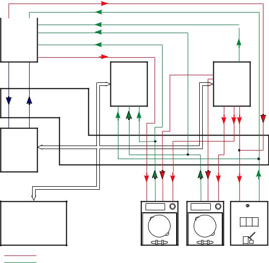
●Blood system test Test description:
Check of the following functions:
–Blood alarm acknowledgement
–Blood pump switch-off
Illustration:
|
X632/C10 |
|
CLP_CTL |
|
|
|
|
|
|
|
X632/C14 |
|
LDA2 |
|
|
X632/C21 |
|
BL_AL |
|
|
|
|||
|
||||
LP 632 |
|
BPSB_VEN |
||
|
||||
|
X632/B11 |
|
||
CPU 2 |
|
|
||
|
|
|||
|
X632/A11 |
|
BPSB_ART |
|
|
|
|
|
|
|
|
|
|
|
|
X632/A15 |
SN_ART |
|
|
|
|
|
|
|
|
X634L/ |
|
|
|
|
|
|
|
|
|
|
|
|
C15 |
|
X632/B27 |
X632/B28 |
LP 633 |
|
|
|
|
X634L/ |
LP 634 |
||||
|
|
|
|
|
|
A14 |
|
(4008E/H) |
||||
|
|
|
|
|
|
|
|
|
||||
|
|
Input |
|
|
|
|
A15 |
|
Output |
|||
|
|
board |
|
|
|
|
|
|
|
board |
||
|
|
|
|
|
|
|
|
ART |
|
|
LP 647 |
|
|
|
|
|
|
|
|
|
_ |
|
|
|
|
|
|
|
|
|
|
|
|
BPST |
|
|
(4008S/B) |
|
|
|
X633L/ |
A13 |
X633L/ |
|
|
|
X634L/ B15 |
X634L/ |
|||
|
|
|
|
|
|
|||||||
|
|
C13 |
|
|
|
|
|
|
|
B14 |
|
C14 |
|
|
|
|
|
|
|
|
|
|
|
||
X631/A20 |
X631/A21 |
|
|
|
|
|
|
|
|
|
|
|
LP 631 |
|
|
|
|
|
|
|
|
|
|
|
|
|
LP 630 |
|
|
|
|
|
|
BPSST_A |
|
|
||
CPU 1 |
DATA BUS |
|
|
|
|
|
|
|
|
|
|
|
|
|
|
|
|
|
|
|
|
|
|
|
|
|
Mother |
|
|
|
|
|
|
|
|
V |
|
|
|
board |
|
|
|
|
|
|
|
|
|
|
|
|
|
|
|
|
|
|
|
|
BPSST |
|
|
|
|
|
|
|
|
|
|
|
|
|
|
|
|
|
|
|
|
X348a/2 |
X348a/6 |
X348a/3 |
X348a/1 |
X348/V6 |
X348/V3 |
X348/V1 |
X351/8 |
X351/6 |
LP 635 |
LP 649 |
|
|
|
|
|
|
|
|
|
Pven |
|
|
|
|
|
|
|
|
|
|
|
|
||
(4008 E) |
(4008 B) |
|
|
|
|
|
|
|
|
|
|
|
Display
board
LP 924 |
LP 922 |
(4008 H) |
(4008 S) |
Testgenerierung/Generation of Test
Rückmeldung/Acknowledgement
1-12 |
Fresenius Medical Care 4008 5/03.09 (TM) |
Error description: |
|
|
Error message |
Description |
|
F09 Bloodsystem |
Acknowledgement that CPU2 recognizes that the arterial blood pump |
|
|
is inactive (BP not running). |
|
|
– Acknowledgement (BPSB_ART, X348a/6) → X632/A11, 12 V miss- |
|
|
|
ing. |
|
– Control line (BPSST_ART, X634L/B14) → X348a/1, 12 V missing or |
|
|
|
(BPST_ART, X634L/A14) → X348a/3, 12 V are missing. |
F10 Bloodsystem |
Acknowledgement that CPU1 recognizes that the arterial blood pump |
|
|
is inactive (BP not running). |
|
|
– Acknowledgement (BPSB_ART, X348a/6) → X633L/A11, 12 V are |
|
|
|
missing. |
|
– Control line (BPSTT_ART, X634L/B14) → X348a/1, 12 V missing or |
|
|
|
(BPST_ART, X634L/A14) → X348a/3, 12 V missing. |
|
– Level is raised during the T1 test. |
|
F11 Bloodsystem |
The arterial blood pump cannot be stopped by CPU1. |
|
|
CPU2 recognizes that the arterial blood pump remains active. |
|
|
– Control line (BPSST_ART, X634L/B14) → X348a/1, 0 V missing, |
|
|
|
as well as (BPST_ART, X634L/A14) → X348a/3, 0 V missing. |
|
– |
Acknowledgement (BPSB_ART, X348a/6) → X632/A11, 0 V are |
|
|
missing. |
|
– The level is raised during the T1 test, or the up/down key on the air |
|
|
|
detector is blocked and the level is constantly raised. |
F12 Bloodsystem |
The arterial blood pump cannot be stopped by CPU1. |
|
|
CPU1 recognizes that the arterial blood pump remains active. |
|
|
– Control line (BPSST_A, X634L/B14) → X348a/1, 0 V missing, |
|
|
|
as well as (BPST_ART, X634L/A14) → X348a/3, 0 V missing. |
|
– Acknowledgement (BPSB_ART, X348a/6) → X633L/A11, 0 V are |
|
|
|
missing. |
F13 Bloodsystem |
Applicable for SW 4.91/2.91 and higher if SN, ONLINE-HDF or |
|
|
4008 HDF pump is connected (= ADKS active) |
|
|
Acknowledgement that CPU2 detects that the pump is inactive (pump |
|
|
is not running). |
|
|
– |
Acknowledgement (BPSB_VEN, X348V/6) → X632/ B11, 12V |
|
|
missing |
|
– Control line (BPSST_VEN, X634L/B15) → X348V/1, 12V missing or |
|
|
|
(BPST_VEN, X634L/A15) → X348V/3, 12V missing |
|
– Transistor T9 on P.C.B. LP 754 defective |
|
|
– IC5 on P.C.B. LP 632 defective |
|
|
– |
In 4008 HDF an HDF treatment was performed, followed by a |
|
|
cleaning program with the substituate pump running, then the T1 |
|
|
test has been re-started. |
|
|
The substituate pump must be switched off because otherwise the |
|
|
test step will fail to be passed (problem was corrected with SW 3.20 |
|
|
in 4008 H/S systems: the substituate pump will be switched off |
|
|
automatically on starting a cleaning program). |
Fresenius Medical Care 4008 5/03.09 (TM) |
1-13 |
F14 Bloodsystem |
Applicable for SW 4.91/2.91 and higher if SN, ONLINE-HDF or |
|
4008 HDF pump is connected (= ADKS active) |
|
Acknowledgement that CPU1 detects that the pump is inactive (pump |
|
is not running). |
|
– Acknowledgement (BPSB_VEN,X348V/6) → X633L/A13, 12V |
|
missing |
|
– Control line (BPSST_VEN, X634L/B15) → X348V/1 not 12V or |
|
(BPST_VEN, X634L/A15) → X348V/3 not 12V |
|
– IC16 on P.C.B. LP 633 defective |
|
– P.C.B. LP 633 recognizes Single-Needle pump although it is not |
|
connected. |
F15 Bloodsystem |
Applicable for SW 4.91/2.91 and higher if SN, ONLINE-HDF or |
|
4008 HDF pump is connected (= ADKS active) |
|
CPU1 fails to stop the corresponding blood pump. |
|
CPU2 detects that the pump remains active. |
|
– Control line (BPSST_VEN, X634L/B15) → X348V/1, 0V missing as |
|
well as (BPST_VEN, X634L/A15) → X348V/3 not 0V |
|
– Acknowledgement (BPSB_VEN, X348V/6) → X632/B11, 0V miss- |
|
ing |
|
– Transistor T9 on P.C.B. LP 754 defective |
|
– IC5 on P.C.B. LP 632 defective |
|
– During the test the lines are inserted on the corresponding pump |
|
using the Start/Stop key. |
|
– P.C.B. LP 633 recognizes Single-Needle pump although it is not |
|
connected. |
F16 Bloodsystem |
Applicable for SW 4.91/2.91 and higher if SN, ONLINE-HDF or |
|
4008 HDF pump is connected (= ADKS active) |
|
CPU1 fails to stop the corresponding blood pump. |
|
CPU1 detects that the pump remains active. |
|
– Control line (BPSST_VEN, X634L/B15) → X348V/1 not 0V as well |
|
as (BPST_VEN, X634L/A15) → X348V/3 not 0V |
|
– Acknowledgement (BPSB_VEN, X348V/6) → X633L/A13 not 0V |
|
– IC16 on P.C.B. LP 633 defective |
|
– P.C.B. LP 633 recognizes Single-Needle pump although it is not |
|
connected. |
F17 Bloodsystem |
Applicable for SW 4.91/2.91 and higher if SN, ONLINE-HDF or |
|
4008 HDF pump is connected (= ADKS active) |
|
Although the recognition of the venous blood pump (ADKS) is not |
|
acknowledged, the 24-V supply voltage of the pump can be switched |
|
off. |
|
– Acknowledgement line (ADKS, X348V/7) → X633L/A10 not 12V |
|
– Acknowledgement (BPSB_VEN, X348V/6) → X633L/A13 not 12V |
|
– Acknowledgement (BPSB_VEN, X348V/6) → X632/B11 not 12V |
|
– Online-HDF has already been switched on during the T1 test. |
|
– IC16 on P.C.B. LP 633 defective. |
1-14 |
Fresenius Medical Care 4008 5/03.09 (TM) |
F18 Bloodsystem Applicable for SW 5.00/4.10 and higher, check of the BPUS signal (CPU, P.C.B. LP 632)
At the beginning of the test step a maximum of 40s may pass until rotation has stopped.If the blood pump is being activated, the rotation stop alarm must have been cleared.
–Acknowledgement line (BPUS, X348A/8) → X632/A13 not 0V
–Acknowledgement line (BPUS, X348A/8) → X632/A13 not 12V
–Blood pump speed is set to “0”: preset speed during the T1 test.
F19 Bloodsystem Applicable for SW 5.00/4.10 and higher, check of the BPUS signal (CPU, P.C.B. LP 631 via LP 633)
At the beginning of the test step a maximum of 40s may pass until rotation has stopped. If the blood pump is being activated, the rotation stop alarm must have been cleared.
1.Acknowledgement line (BPUS, X348A/8) → X633L/A12 not 0V
2.Acknowledgement line (BPUS, X348A/8) → X633L/A12 not 12V
F20 Bloodsystem Check of the actual arterial BP rate.
The actual rate of the arterial BP is not zero. The actual rate of the arterial BP does not increase.
If SN is installed: The actual rate of the venous BP is not zero. The actual rate of the venous BP does not increase.
–Acknowledgement line (BPR_ART, X348A/10) → X633L/B3 not 0V or acknowledgement line (BPR_ART, X348A/10) → X632/A14 not 0V
–Acknowledgement line (BPR_ART, X348A/10) → X633L/B3 no increase or acknowledgement line (BPR_ART, X348A/10) → X632/ A14 no increase
If SN is installed:
–Acknowledgement line (BPR_VHDF, X348V/10) → X633L/B4 not 0V
–Acknowledgement line (BPR_VHDF, X348V/10) → X633L/B4 no increase
F95 Bloodsystem |
System error. |
Fresenius Medical Care 4008 5/03.09 (TM) |
1-15 |
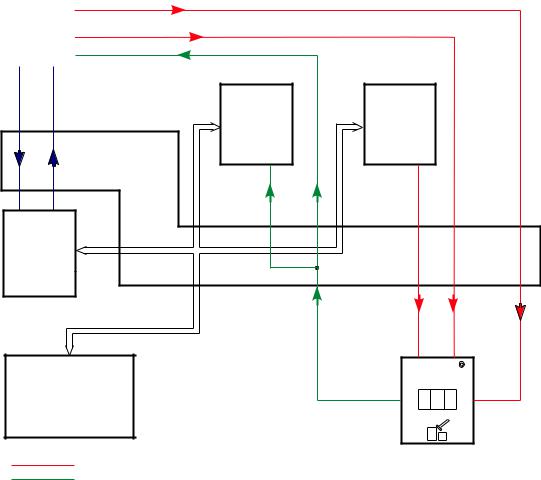
●Venous pressure system test Test description:
Verification of the lower limit by checking the venous zero point.
The upper limit is tested by detuning the venous pressure unit in positive direction. (The venous line clamp is closed during the test.)
Illustration:
LP 632 |
X632/C16 |
|
LDSA |
||
|
|
||||
CPU 2 |
|
|
|
|
|
X632/C18 |
|
PV_DET |
|||
|
|
||||
|
X632/C17 |
|
P_VEN |
||
|
|
|
|
|
|
X632/B27 X632/B28
LP 633 |
LP 634 |
|
|
Input |
Output |
|
|
board |
board |
|
|
X633L/B5 |
X634R/C18 |
|
|
|
V |
X631/A20 |
X631/A21 |
|
VENT |
|
|
||
LP 631 |
|
|
|
CPU 1 |
LP 630 |
DATA BUS |
|
|
|
|
|
|
Mother |
|
|
|
board |
|
|
|
X351/1 |
X351/2 |
LP 635 |
LP 649 |
PVEN |
(4008 E) |
(4008 B) |
|
Display |
|
|
||
board |
X351/4 |
X351/10 |
||
LP 924 |
LP 922 |
|||
|
|
|||
(4008 H) |
(4008 S) |
|
|
|
Testgenerierung/Generation of Test
Rueckmeldung/Acknowledgement
1-16 |
Fresenius Medical Care 4008 5/03.09 (TM) |
Error description |
|
Error message |
Description |
F01 Venous |
CPU1 (input board) shows a venous zero point deviation of more than |
|
±12 mmHg (60 s). |
|
– Control (VENT_VALVE, X634R/C18) → X351/1 of the vent valve in |
|
the LD is defective. |
|
– Acknowledgement (P_VEN, X351/4) → X633L/B5 that the voltage |
|
value is outside the zero point tolerance. |
|
– P-venous has not been calibrated. |
F02 Venous |
CPU2 shows a venous zero point deviation of more than ±12 mmHg |
|
(60 s). |
|
– Control (VENT_VALVE, X634R/C18) → X351/1 of the vent valve in |
|
the LD is defective. |
|
– Acknowledgement (P_VEN, X351/4) → X632/C17, the voltage |
|
value is outside the zero point tolerance. |
|
– P-venous has not been calibrated. |
F03 Venous |
With detuning in positive direction, the achieved change in the venous |
|
display is less than 100 mmHg (7 s). |
|
– The test detuning is defective (PV_DET, X632/C18) → X351/2. |
|
– Acknowledgement (P_VEN, X351/4) → X633L/B5, the change in |
|
voltage is too low. |
|
– P-venous has not been calibrated. |
F04 Venous |
The deviation in the measured value between CPU1 and CPU2 is |
|
higher than ±12 mmHg (if Pven > 100 mmHg). |
|
– Acknowledgement (P_VEN, X351/4) → X633L/B5 and X632/C17 |
|
measure different voltage values. |
|
– P-venous has not been calibrated. |
F95 Venous |
System error. |
Fresenius Medical Care 4008 5/03.09 (TM) |
1-17 |
●Air detector test Test description:
–Test of the air detector by checking the alarm state.
–Switch-off of the venous line clamp in the air detector module.
Illustration:
1-18 |
Fresenius Medical Care 4008 5/03.09 (TM) |
Error description: |
|
Error message |
Description |
F01 Airdetector |
CPU1 interprets the air detector signal in a different way than does |
|
CPU2. |
|
– Acknowledgements (LDA1, X351/14) → X632/C13 and X633L/C10 |
|
recognize different signal levels. |
F02 Airdetector |
The air detector alarm is not recognized by CPU2. |
|
– Acknowledgement (LDA1, X351/14) → X632/C13, 0 V are missing. |
|
– Transmission weakening (LDSA, X632/C16) → X351/10, 12 V are |
|
missing. |
F03 Airdetector |
Air detector clamps acknowledgement (CPU2) activated (clamp |
|
closed). |
|
– Acknowledgement (LDA2, X351/6) → X632/C14, 24 V are missing. |
|
– Clamp control (CLP_CTL, X634L/C14) → X351/8, 12 V are missing. |
|
– Clamp control (CLP_CTL, X632/C10) → X351/8, 12 V are missing. |
F04 Airdetector |
Air detector clamps acknowledgement (CPU1) activated (clamp |
|
closed). |
|
– Acknowledgement (LDA2, X351/6) → X633L/C13, 24 V are miss- |
|
ing. |
|
– Clamp control (CLP_CTL, X634L/C14) → X351/8, 12 V are missing. |
|
– Clamp control (CLP_CTL, X632/C10) → X351/8, 12 V are missing. |
F05 Airdetector |
The blood alarm signal has not been cleared (indicates an alarm). |
|
– Acknowledgement (BL_AL, X634L/C15) → X632/C21, 12 V are |
|
missing. |
|
If the HDF option is used, this signal is not tested (special function). |
F06 Airdetector |
Closing of the air detector clamp via the CPU2 control line was not |
|
possible. |
|
– Clamp control (CLP_CTL, X632/C10) → X351/8, 0 V are missing. |
|
– Acknowledgement (LDA2, X351/6) → X632/C14, 0 V are missing. |
F07 Airdetector |
Opening of the air detector clamp via the CPU2 control line was not |
|
possible. |
|
– Clamp control (CLP_CTL, X632/C10) → X351/8, 12 V are missing. |
|
– Acknowledgement (LDA2, X351/6) → X632/C14, 24 V are missing. |
F08 Airdetector |
Closing of the air detector clamp via the CPU1 control line was not |
|
possible, or CPU2 acknowledgement is incorrect. |
|
– Clamp control (CLP_CTL, X634L/C14) → X351/8, 0 V are missing. |
|
– Acknowledgement (LDA2, X351/6) → X632/C14, 0 V are missing. |
Fresenius Medical Care 4008 5/03.09 (TM) |
1-19 |
F09 Airdetector |
Closing of the air detector clamp via the CPU1 control line was not |
|
|
possible, or CPU1 acknowledgement is incorrect. |
|
|
– Clamp control (CLP_CTL, X634L/C14) → X351/8, 0 V are missing. |
|
|
– Acknowledgement (LDA2, X351/6) → X633L/C13, 0 V are missing. |
|
F10 Airdetector |
The blood alarm message is missing. |
|
|
– |
Acknowledgement (BL_AL, X634R/C15) → X632/C21, 0 V are |
|
|
missing. |
|
|
If the HDF option is used, this signal is not tested (special function). |
F11 Airdetector |
Air detector clamps acknowledgement (CPU2) activated (clamp |
|
|
closed). |
|
|
– Acknowledgement (LDA2, X351/6) → X632/C14, 24 V are missing. |
|
|
– Clamp control (CLP_CTL, X634L/C14) → X351/8, 12 V are missing. |
|
|
– Clamp control (CLP_CTL, X632/C10) → X351/8, 12 V are missing. |
|
F12 Airdetector |
Air detector clamps acknowledgement (CPU1) activated (clamp |
|
|
closed). |
|
|
– Acknowledgement (LDA2, X351/6) → X633L/C13, 24 V are miss- |
|
|
|
ing. |
|
– Clamp control (CLP_CTL, X634L/C14) → X351/8, 12 V are missing. |
|
|
– Clamp control (CLP_CTL, X632/C10) → X351/8, 12 V are missing. |
|
F13 Airdetector |
The blood alarm signal has not been cleared (indicates alarm). |
|
|
– |
Acknowledgement (BL_AL, X634L/C15) → X632/C21, 12 V are |
|
|
missing. |
|
|
If the HDF option is used, this signal is not tested (special function). |
F14 Airdetector |
Raise level key on the air detector is constantly active. |
|
|
– Acknowledgement (LEVEL_UP, X351/3) → X632/C11 not 0V. |
|
F15 Airdetector |
Acknowledgement of the supply voltage for the ultrasonic output stage |
|
|
not between 6.5 and 13.5 V after 3 seconds. |
|
|
– Adapter board AD28 not connected |
|
|
– |
Acknowledgement (X351/11 → X633L/25A jumper to X633L/B7) |
|
|
not 12V. |
|
– Relay on AD28 failed to drop. |
|
F16 Airdetector |
Acknowledgement of the supply voltage for the ultrasound output stage |
|
|
not >14.5V after 3 seconds. |
|
|
– Adapter board AD28 not connected. |
|
|
– |
Acknowledgement (X351/11 → X633L/25A jumper to X633L/B7) |
not 16V/24V.
– Relay on AD28 is not controlled.
– No 10-Hz signal at ALARM_REST (X351/12)
1-20 |
Fresenius Medical Care 4008 5/03.09 (TM) |
F17 Airdetector |
Acknowledgement of the supply voltage for the ultrasound output stage |
|
not between 6.5 and 13.5 V after 3 seconds. |
|
– Adapter board AD28 not connected |
|
– Acknowledgement (X351/11 → X633L/25A jumper to X633L/B7) |
|
not 12V |
|
– Relay on AD28 failed to drop |
F95 Airdetector |
System error. |
Fresenius Medical Care 4008 5/03.09 (TM) |
1-21 |
●Display test Test description:
Check of all displays and indicators on the monitor front
–Display test
–Status LED
–Alarm LED
–Seven-segment display, all dark
–Seven-segment display, all 8888
–Bar graph
–CPU1/CPU2 alarm tone
This display test must be monitored by the user!
Illustration:
|
LP 632 |
X632/C29 |
CPU2_AL |
|
|
|
||
|
CPU 2 |
|
|
|
|
|
|
|
|
|
|
|
|
|
|
|
X634R/A16 |
|
|
|
|
|
LP 633 |
|
LP 634 |
|
|
|
|
|
|
Input |
|
Output |
|
X632/ B27 |
X632/ B28 |
|
||||||
|
|
|
|
|
board |
|
board |
|
|
|
|
|
|
|
|
|
|
+LS X634L/A13 -LS X634L/B13
X631/ A20 |
X631/ A21 |
|
LP 631 |
|
|
CPU 1 |
LP 630 |
DATA BUS |
|
|
|
|
Mother |
|
|
board |
|
LP 635 |
LP 649 |
|
|
|
|
|||||
(4008 |
E) |
(4008 |
B) |
|
|
|
|
|||
|
Display |
|
|
|
|
|
|
|
|
|
|
|
|
|
|
|
|
|
|
||
|
board |
|
|
|
|
|
|
|
|
|
LP 924 |
LP 922 |
|
|
|
|
|||||
(4008 |
H) |
(4008 |
S) |
|
|
|
|
|
|
|
|
|
|
|
|
|
|
|
|
|
|
|
|
|
|
|
|
|
|
|
|
|
|
|
|
|
|
|
|
|
|
|
|
Test Display
8888
8888
8888
8888
Testgenerierung/Generation of Test
Rueckmeldung/Acknowledgement
1-22 |
Fresenius Medical Care 4008 5/03.09 (TM) |
Loading...