


 Loading...
Technical Manual for COM.TEC
The Technical Manual contains all information necessary for performing maintenance and repair work.
The blood cell separator reflects the latest technology and complies with the requirements of IEC 601, Part 1.
It belongs to safety class I and should be only used in rooms reserved for medical use in accordance with VDE 0107.
Assembly, update, readjustment, modification and repair work should be performed only by the manufacturer or by persons authorized by him.
Fresenius
P |
P |
P3 |
|
|
COM.TEC |
P3 |
|
|
|
|
|
|
|
|
|
|
|
|
|
|
|
|
|
|
|
|
|
|
|
|
0-1 |
|
|
|
|
|
|
|
|
|
|
|
|
|
|
|
|
|
|
|
|
|
|
|
|
|
|
|
|
|
|
|
|
|
|
|
|
|
|
|
|
|
|
|
|
|
|
|
|
|
|
|
|
|
|
|
|
|
|
|
|
|
|
|
|
|
|
|
|
|
|
|
|
|
|
|
|
|
|
|
|
|
|
|
|
|
|
|
|
|
|
|
|
|
|
|
|
|
|
|
|
|
|
|
|
|
|
|
|
|
|
|
|
|
|
|
|
|
|
|
|
|
|
|
|
|
|
|
|
|
|
|
|
|
|
|
|
|
|
|
|
|
|
|
|
|
|
|
|
|
|
|
|
|
|
|
|
|
|
|
|
|
|
|
|
|
|
|
|
|
|
|
|
|
|
|
|
|
|
|
|
|
|
|
|
|
|
|
|
|
|
|
|
|
|
|
|
|
|
|
|
|
|
|
|
|
|
|
|
|
|
|
|
|
|
|
|
|
|
|
|
|
|
|
|
|
|
|
|
|
|
|
|
|
|
|
|
|
|
|
|
|
|
|
|
|
|
|
|
|
|
|
|
|
|
|
|
|
|
|
|
|
|
|
|
|
|
|
|
|
|
|
|
|
|
|
|
Part No. 679 469 1 |
Fresenius HemoCare COM.TEC 1/04.01 (TM) |
|||||||||||||||||||||
Any inquiries should be addressed to:
Manufacturer:
Fresenius HemoCare Deutschland GmbH
Produktionsbereich Geräte
Hafenstrasse 9
D-97424 Schweinfurt
Tel.: ++49 9721/678-0
Fax: ++49 9721/678-200
National Service:
Fresenius Transfusions GmbH
Landsteinerstrasse 5
D-63303 Dreieich
Tel.: ++49 6103/801-0
Fax: ++49 6103/801-672
0-2 Fresenius HemoCare COM.TEC 1/04.01 (TM)
How to Use the Technical Manual
Search and Find |
What? |
Where? |
|
|
Table of contents |
Page 0-5 and at the beginning of each chapter |
|
Intended Use |
This manual is intended for: |
||
|
– first studies (to acquire a basic knowledge) |
||
|
– reference purposes (for start-up, maintenance and repair) |
||
Organization |
The manual is divided into 6 chapters: |
||
|
0 |
General Information |
|
|
1 |
Config.Sys, Service.Sys, CCS Program |
|
|
2 |
Repair / Adjustment / Maintenance |
|
|
3 |
Circuit Descriptions and Circuit Diagrams |
|
|
4 |
Spare Parts Catalog |
|
|
5 |
Start-up and TSC |
|
Page Identification |
Page identification 1-3 is to be interpreted as: Chapter 1, page 3. |
||
Qualification |
This manual is intended to assist service technicians and assumes the following: |
||
|
– that the user is familiar with the current operating instructions |
||
|
– that he has the necessary background experience in mechanics, electrical |
||
|
|
engineering and medical engineering; |
|
|
– that he has been authorized by the manufacturer to perform maintenance and |
||
|
|
repair work; |
|
|
– that he has access to the necessary auxiliary and measuring equipment. |
||
Limitations |
This manual is not intended to provide an alternative to instruction courses |
||
|
offered by the manufacturer. |
||
Manual changes |
Manual changes will be released as new editions, supplements or product |
||
|
information. |
|
|
Note:
Any modifications to circuit and component layout diagrams (SP/BP) do not always affect footers (edition).
The current state of these diagrams is indicated in the index field of each respective SP/BP.
The user/technician can use the respective marking on the printed circuit board to verify whether the SP/BP comply with the actually existing printed circuit board in the machine.
In general, this manual will be subject to modification.
Fresenius HemoCare COM.TEC 1/04.01 (TM) |
0-3 |
Specification |
Unless otherwise specified, potentials indicated in circuit diagrams and calibra- |
||||||
|
tion instructions are related to the perinent ground. |
||||||
Component |
For example, |
|
|
24 means ground for the 24 V voltage. |
|||
|
|
||||||
|
|
||||||
Example: |
|
|
|
|
|
||
identification in |
|
|
75 |
|
|
||
circuit diagrams |
|
|
|
|
|||
|
|
|
|
|
|
|
|
|
|
|
|
|
|
|
|
|
|
|
|
|
|
|
|
|
|
|
|
|
|
|
|
1R2
This refers to a resistor with position number 75 and a resistance of 1.2 ohm.
The decimal point used to indicate the value is replaced by a unit symbol (to reduce the possibility of errors).
|
Resistors |
|
Capacitors: |
|
|
|
R1: |
0.1 Ω |
µ 1: |
0.1 µ |
F |
|
1R2: |
1.2 Ω |
1µ 2: |
1.2 µ |
F |
|
1K2: |
1.2 kΩ |
1000µ : |
1000µ F |
|
Note |
When repairing blood cell separators and replacing spare parts, observe the |
||||
|
protective ESD measures to be taken to prevent electrostatic discharge (e.g. |
||||
|
EN 100 015-1). |
|
|
|
|
Technical Data |
The technical data of the COM.TEC Blood Cell Separator are listed in the |
||||
|
Operating Instructions. |
|
|
|
|
0-4 Fresenius HemoCare COM.TEC 1/04.01 (TM)
Table of Contents
Chapter |
|
Page |
1 |
Config.Sys, Service.Sys, CCS Program ..................................................................... |
1- |
1.1 |
Config.sys ....................................................................................................................... |
1-3 |
1.2 |
Service.sys ...................................................................................................................... |
1-9 |
1.3 |
PC E53 ............................................................................................................................ |
1-11 |
1.4 |
SERVICE TOOL for COM.TEC ....................................................................................... |
1-13 |
2 |
Repair / Adjustment / Maintenance ............................................................................. |
2- |
2.1 |
Verification of the Interface Detection ............................................................................. |
2-5 |
2.2 |
Adjustment of the Interface Detection ............................................................................. |
2-12 |
2.3 |
C5 Interface Sensitivity ................................................................................................... |
2-22 |
2.4 |
Verification of the C5 Illuminance ................................................................................... |
2-24 |
2.5 |
Inlet Pressure Monitor ..................................................................................................... |
2-26 |
2.6 |
Outlet Pressure Monitor .................................................................................................. |
2-31 |
2.7 |
P3 Monitor ....................................................................................................................... |
2-36 |
2.8 |
Operating Voltages / Battery Voltage ............................................................................. |
2-41 |
2.9 |
Air Detector ..................................................................................................................... |
2-42 |
2.10 |
Optical Detector in Air Detector ...................................................................................... |
2-44 |
2.11 |
Hb/Hct Detector .............................................................................................................. |
2-45 |
2.12 |
Spillover Detector ........................................................................................................... |
2-47 |
2.13 |
Substituate-Empty Detector ............................................................................................ |
2-49 |
2.14 |
Gap Width of Outlet Clamp ............................................................................................. |
2-51 |
2.15 |
Line Pumps ..................................................................................................................... |
2-52 |
2.16 |
Clamps ............................................................................................................................ |
2-55 |
2.17 |
Centrifuge Door ............................................................................................................... |
2-57 |
2.18 |
Door Switch ..................................................................................................................... |
2-59 |
2.19 |
Centrifuge Motor Carbon Brushes .................................................................................. |
2-61 |
2.20 |
Single Needle / Cuff Control ........................................................................................... |
2-62 |
2.21 |
Removal and Installation of the Centrifuge Rotor .......................................................... |
2-64 |
2.22 |
Tightening the Belts in the Rotor .................................................................................... |
2-68 |
2.23 |
Brake ............................................................................................................................... |
2-69 |
2.24 |
Flutter Detector ............................................................................................................... |
2-70 |
2.25 |
General Mechanical Checks ........................................................................................... |
2-71 |
3 |
Circuit Descriptions and Circuit Diagrams ............................................................... |
3- |
3.1 |
Rear View of the COM.TEC Housing Top Part .............................................................. |
3-3 |
3.2 |
Rear View of the COM.TEC Housing Bottom Part ........................................................ |
3-4 |
3.3 |
COM.TEC Block Diagram ............................................................................................... |
3-5 |
3.4 |
CAN Chain Block Diagram .............................................................................................. |
3-7 |
3.5Block Diagram of the Power Supply Separation
|
COM.TEC Control and Safety System ........................................................................... |
3-9 |
|
3.6 |
Voltage Supply Block Diagram ....................................................................................... |
3-11 |
|
3.7 |
P.C.B. LP-Z 175 Single Needle ...................................................................................... |
3-13 |
|
3.8 |
P.C.B. LP-Z 241 Air Monitoring System.......................................................................... |
3-17 |
|
3.9 |
P.C.B. LP 821 CAN/PC Card .......................................................................................... |
3-23 |
|
3.10 |
P.C.B. LP 822 Keyboard Board ...................................................................................... |
3-29 |
|
3.11 |
P.C.B. LP 823-1 Power Control Logic and Door Switch ................................................ |
3-33 |
|
3.12 |
P.C.B. LP 826 Power Module Box .................................................................................. |
3-43 |
|
3.13 |
P.C.B. LP 828 Dual Stroboscope .................................................................................... |
3-49 |
|
3.14 |
P.C.B. LP 829 |
Flash Tube Board.................................................................................... |
3-55 |
3.15 |
P.C.B. LP 830 |
CAN-I/O Card .......................................................................................... |
3-59 |
3.16 |
P.C.B. LP 840 |
Alarm System .......................................................................................... |
3-67 |
3.17 |
P.C.B. LP 841 |
Safety System ......................................................................................... |
3-77 |
Fresenius HemoCare COM.TEC 1/04.01 (TM) |
0-5 |
Chapter |
|
Page |
3.18 |
P.C.B. LP 852 Pump Control .......................................................................................... |
3-83 |
3.19 |
P.C.B. LP 854 Logik Centrifuge Control Logic ............................................................... |
3-87 |
3.20 |
P.C.B. LP 855 Centrifuge Control ................................................................................... |
3-91 |
3.21 |
P.C.B. LP 857 Supply Voltage ........................................................................................ |
3-97 |
3.22 |
P.C.B. LP 860 Camera Logic .......................................................................................... |
3-103 |
3.23 |
P.C.B. LP 861 Camera Sensor ....................................................................................... |
3-107 |
3.24 |
P.C.B. LP 863 Interface Detection .................................................................................. |
3-111 |
3.25 |
P.C.B. LP 864 Computer Bus Board............................................................................... |
3-115 |
3.26 |
P.C.B. LP 865 Electronics Bus Board ............................................................................. |
3-119 |
3.27 |
P.C.B. LP 866 COM.TEC-I/O Card ................................................................................. |
3-123 |
3.28 |
P.C.B. LP 867 ACD Pump Unit ....................................................................................... |
3-133 |
3.29 |
P.C.B. LP 868 Camera Lighting ...................................................................................... |
3-145 |
3.30 |
P.C.B. LP 869 Clamp Control ......................................................................................... |
3-149 |
3.31 |
P.C.B. LP 870 Pressure Monitor ..................................................................................... |
3-159 |
3.32 |
P.C.B. LP 945 Printer Adapter (Seiko) ........................................................................... |
3-169 |
4 |
Spare Parts Catalog ...................................................................................................... |
4- |
5 |
Start-Up and TSC .......................................................................................................... |
5- |
5.1 |
Instructions for Initial Start-Up ........................................................................................ |
5-3 |
5.2 |
Technical Safety Checks ................................................................................................ |
5-7 |
0-6 Fresenius HemoCare COM.TEC 1/04.01 (TM)
Table of Contents
1 Config.Sys, Service.Sys, CCS Program
Chapter |
|
Page |
1.1 |
Config.sys ...................................................................................................................... |
1-3 |
1.1.1 |
Configuration Donation ................................................................................................... |
1-4 |
1.1.2 |
Configuration Therapy .................................................................................................... |
1-7 |
1.1.3 |
Configuration General ..................................................................................................... |
1-8 |
1.2 |
Service.sys .................................................................................................................... |
1-9 |
1.2.1 |
Display ............................................................................................................................ |
1-10 |
1.2.2 |
IF set ............................................................................................................................... |
1-10 |
1.2.3 |
max. RPM ....................................................................................................................... |
1-10 |
1.2.4 |
Machine No. .................................................................................................................... |
1-10 |
1.2.5 |
Max. temp ....................................................................................................................... |
1-10 |
1.2.6 |
Expertmode ..................................................................................................................... |
1-10 |
1.2.7 |
DCS ................................................................................................................................ |
1-10 |
1.3 |
PC E53 ............................................................................................................................ |
1-11 |
1.3.1 |
Flash Disc ....................................................................................................................... |
1-11 |
1.3.2 |
PCMCIA Card ................................................................................................................. |
1-11 |
1.3.3 |
Signals ............................................................................................................................ |
1-12 |
1.3.4 |
BIOS Setup ..................................................................................................................... |
1-12 |
1.4 |
SERVICE TOOL for COM.TEC ...................................................................................... |
1-13 |
1.4.1 |
How to access the SERVICE TOOL for COM.TEC ....................................................... |
1-13 |
1.4.2 |
Working with the CCS Program ...................................................................................... |
1-14 |
1.4.3 |
Power Supply .................................................................................................................. |
1-15 |
1.4.4 |
Pumps ............................................................................................................................. |
1-16 |
1.4.5 |
Clamps ............................................................................................................................ |
1-17 |
1.4.6 |
ASTEC IO1 ..................................................................................................................... |
1-18 |
1.4.7 |
ASTEC IO2 ..................................................................................................................... |
1-20 |
1.4.8 |
HBHK / spillover .............................................................................................................. |
1-21 |
1.4.9 |
CCD Camera .................................................................................................................. |
1-22 |
Fresenius HemoCare COM.TEC 1/04.01 (TM) |
1-1 |
1-2 Fresenius HemoCare COM.TEC 1/04.01 (TM)
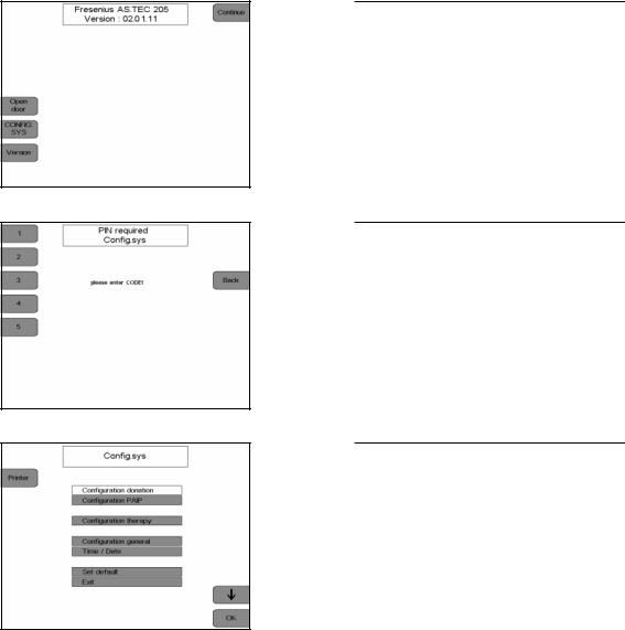
1.1Config. Sys
The basic configuration of the COM.TEC can be changed in the Config.sys.
Display
Press the CONFIG.SYS key.
Display
Enter the code 1 3 5 2 4 with the numeric keys.
The Config.Sys codes can be entered as often as desired.
The Config.Sys screen displays.
Select the desired configuration with the  and
and  keys.
keys.
Press the OK key.
The selected menu option displays.
Fresenius HemoCare COM.TEC 1/04.01 (TM) |
1-3 |
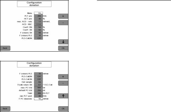
1.1.1Configuration Donation
Display
Select the values to be altered by pressing the  and
and  keys.
keys.
Alter the values by pressing the + and – keys.
Press the OK key to save all changes.
To exit the configuration menu and to return to the previous screen, press the
Back key.
–Menu
Donor menu and donor data display can be activated and deactivated.
–PLT pre
Presetting of the donor’s mean platelet pre-value.
–HCT pre
Presetting of the donor’s mean HCT pre-value.
–Max. ACD-rate
Setting of the ACD rate per liter of whole blood volume tolerated by the donor.
–ACD:RBC
The ACD:RBC ratio influences the ACD: WB ratio based on the hematocrit. The pH value is optimized in the storage bag.
–Coeff. DN
Operand for adapting the yield to the predicted value.
–Coeff. SN
Operand for adapting the yield to the predicted value.
–F(return)SN
Adjustment of the return flow rate to the donor.
1-4 Fresenius HemoCare COM.TEC 1/04.01 (TM)
–F(return)PLS
Adjustment of the blood pump flow during the SN return phase with active plasma collection.
–PLS-Coll.DN
Preselection of automatic plasma collection and selection of the volume to be separated (Off
=0). Dual needle.
–PLS-Coll.SN
Preselection of automatic plasma collection and selection of the volume to be separated (Off
=0). Single needle.
–Get sample
Selection and deselection of help texts for sample collection. Single needle.
–F(cell) return SN
Factor for the cell flow in the return phase. Single needle.
–max. PC-Vol
Determination of the maximum collection volume for the platelet concentrate.
–default PC-Vol
Selection of the standard PC volume.
–Yield
Preadjustment of the platelet yield.
–min. PLT post
Threshold for the donor’s PLT-post value which causes a warning when reached.
–F PC deaerate
Selection of the plasma pump flow during deaeration of the platelate concentrate (Off = 0)
Fresenius HemoCare COM.TEC 1/04.01 (TM) |
1-5 |
● Increments and limits for donation parameter configuration
|
Default |
Increment |
Max. |
Min. |
|
|
|
|
|
Menus |
On |
– |
On |
Off |
|
|
|
|
|
PLTpre |
265 x E9/L |
1 x E9/L |
400 x E9/L |
100 x E9/L |
|
|
|
|
|
HCT pre |
40% |
1% |
60% |
20% |
|
|
|
|
|
max. ACD-rate |
1.1ml/min/L |
0.1 ml/min/L |
2.2 ml/min/L |
0.1 ml/min/L |
|
|
|
|
|
ACD:RBC |
1:3.2 |
0.1 |
1:5.0 |
1:2.0 |
|
|
|
|
|
Coeff. DN |
49% |
1% |
70% |
30% |
|
|
|
|
|
Coeff. SN |
59% |
1% |
70% |
30% |
|
|
|
|
|
F(return) SN |
75 ml/min |
1 ml/min |
200 ml/min |
50 ml/min |
|
|
|
|
|
F(return) PLS |
35 ml/min |
1 ml/min |
70 ml/min |
35 ml/min |
|
|
|
|
|
PLS-Coll. DN |
Off |
10 ml |
500 ml |
Off, 50 ml |
|
|
|
|
|
PLS-Coll. SN |
Off |
10 ml |
500 ml |
Off, 50 ml |
|
|
|
|
|
Get sample |
On |
– |
On |
Off |
|
|
|
|
|
F(cell) return SN |
0.7*F(c) coll |
0.1*F(c)coll |
2.0*F(c)coll |
0.1*F(c)coll |
|
|
|
|
|
max. PC-Vol |
600 ml |
10 ml |
1500 ml |
600 ml |
|
|
|
|
|
default PC-Vol |
250 ml |
10 ml |
600 ml |
100 ml |
|
|
|
|
|
Yield |
300 x E9 |
10 x E9 |
1500 x E9 |
50 x E9 |
|
|
|
|
|
min. PLT post |
80 E9/L |
1 E9/L |
150 E9/L |
50 E9/L |
|
|
|
|
|
F PC deaerate |
50 ml/min |
1 ml/min |
120 ml/min |
Off, 10 ml |
1-6 Fresenius HemoCare COM.TEC 1/04.01 (TM)

1.1.2Configuration Therapy
Display
–Menus
Selection and deselection of the TPE and RBC menus.
–HCT pre
Preadjustment of the patient’s hematocrit value for calculation of the menus.
–HCT RBC
Preadjustment of the hematocrit value, which is adjusted by the Hct controller (see controller options) in the RBC line. During the RBC procedure, this value is computed and changed correspondingly by the menu.
Fresenius HemoCare COM.TEC 1/04.01 (TM) |
1-7 |
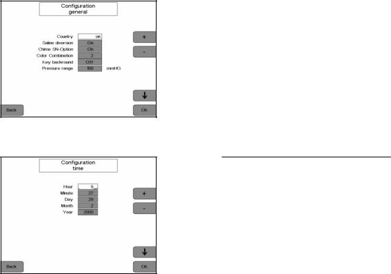
1.1.3Configuration General
– Configuration time
Setting of year, day, hour, minute.
–Country
The country version changes language, units and clock to national conventions.
–Saline diversion
Activates and deactivates saline diversion.
–Chime SN-Option
Activates the chime if no automatic cuff is used.
–Colour combination
Setting the colour combination of the display.
–Key background
Switching the key background on and off.
–Pressure range
Selects the pressure range for the inlet pressure monitor which initiates a pre-alarm if the inlet pressure drops.
Default: 100 mmHg
1-8 Fresenius HemoCare COM.TEC 1/04.01 (TM)
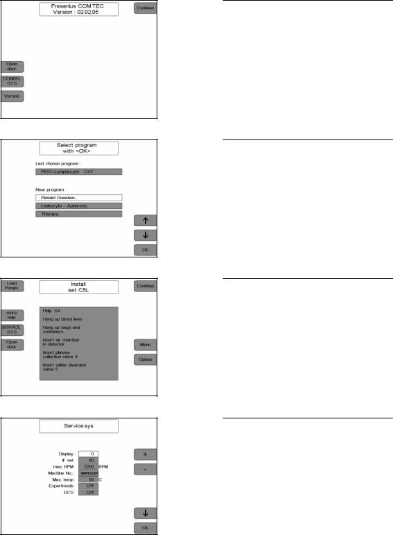
1.2Service.sys
Display.
Press the Continue key.
Display.
Press the 2nd, the 4th and the 1st key to the left of the display one after the other.
Press the OK key.
Display.
Press the SERVICE.SYS key.
The Service.Sys screen is displayed.
Select the desired program item by pressing the  and
and  keys.
keys.
Fresenius HemoCare COM.TEC 1/04.01 (TM) |
1-9 |
1.2.1Display
Selection of the program phase window
1.2.2IF set
Adjustment of the interface sensitivity
1.2.3max. RPM
Maximum centrifuge speed set to 2200 rpm
1.2.4Machine No.
Possibility to enter the machine no. shown on the type label
1.2.5Max. temp
Indication of the maximum temperature that prevailed inside the centrifuge
1.2.6Expertmode
Possibility to create RAM programs
1.2.7DCS
Activation/deactivation of the optional radio communication interface
1-10 Fresenius HemoCare COM.TEC 1/04.01 (TM)
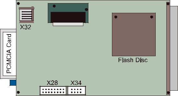
1.3PC E53
Fig.: PC E53
1.3.1Flash Disc
The Flash Disc is incorporated as system drive C:\ and contains the DOS system, the program control and display software.
1.3.2PCMCIA Card
The PCMCIA Card is incorporated in the system as drive C:\. In this case, the Flash Disc automatically becomes drive D:\.
The PCMCIA Card contains the current program control and display software (in case of a software update) and the diagnosis/service program.
Fresenius HemoCare COM.TEC 1/04.01 (TM) |
1-11 |

1.3.3Signals
|
LCD/X33 |
|
|
X32 |
||
|
|
|
|
|
|
|
PIN |
|
Signal |
|
PIN |
|
Signal |
|
|
|
|
|
|
|
1 |
|
VS |
|
1 |
|
GND |
2 |
|
HS |
|
2 |
|
DATA |
3 |
|
VCKL |
|
3 |
|
VCC |
4 |
|
nc |
|
4 |
|
CLK |
5 |
|
nc |
|
|
|
|
|
|
|
|
|
||
6 |
|
_Blank |
|
|
|
|
7 |
|
nc |
|
|
|
|
8 |
|
VID |
|
|
|
|
9 |
|
nc |
|
|
|
|
– |
|
nc |
|
|
|
|
|
|
|
|
|
|
|
1.3.4BIOS Setup
The BIOS setup is accessed by pressing the Ctrl + Alt + F6 keys, when turning power on to the COM.TEC.
E 5 3 S E T U P P R O G R A M
DISK DRIVE |
0 TYP 0: NOT INSTALLED |
|
DISK DRIVE |
1 TYP 0: NOT INSTALLED |
|
|
|
|
PCMCIA - ATA / IDE BOOT DRIVE SELECT |
|
|
BOOT FROM 1: ATA-CARD |
ATA-BIOS EXT : YES |
|
|
|
|
SHOW BOOT MESSAGES: NO |
KEYBOARD TEST: NO |
|
SELECT DISPLAY TYPE: AUTO
POST WAIT TIME IN SECONDS: 00
BOOT FROM: HARD DISC
CTL ALT DEL RESET: ACTIVATE HW
COM3 / COM4 IRQ: 4 / 3
ALL INPUTS ARE CORRECT? (1)
KEYS: <↑ > CHANGE VALUE, <RET> NEXT ITEM
1-12 Fresenius HemoCare COM.TEC 1/04.01 (TM)
1.4SERVICE TOOL for COM.TEC
1.4.1How to access the SERVICE TOOL for COM.TEC
–Turn the COM.TEC power off.
–Insert the PCMCIA card in the PC.
–Connect the external keyboard to X32 / PC.
–Turn the COM.TEC power on.
–Press the  key.
key.
–The Service Tool for COM.TEC screen displays.
–The following options are available:
Menu |
key |
Menu |
key |
Menu |
key |
|
|
|
|
|
|
Service Tool |
S |
|
|
|
|
|
|
|
|
|
|
Update |
U |
Software Update to |
A |
Select BIOS Version |
|
|
|
|
|
BIOS E53 00.01.06 |
A |
|
|
|
|
BIOS E53 00.01.07 |
B |
|
|
|
|
|
|
|
|
System Config |
C |
Install DCS Driver |
I |
|
|
|
|
Deinstall DCS Driver |
D |
|
|
|
|
Exit Update |
E |
|
|
|
|
|
|
|
|
EXIT UPDATE |
E |
|
|
|
|
|
|
|
|
– The desired option is selected by pressing the associated key.
Fresenius HemoCare COM.TEC 1/04.01 (TM) |
1-13 |
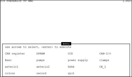
1.4.2Working with the CCS program
–Use the cursor to select the desired menu.
–Display the menu selected by pressing the  key.
key.
–Press the Esc key to exit the respective menu.
–To exit the CCS program, select quit using the cursor and confirm this selection by pressing the  key.
key.
–Within the CCS program, menu-specific help is available, which can be displayed by pressing the F1 key.
1-14 Fresenius HemoCare COM.TEC 1/04.01 (TM)
1.4.3Power Supply
accu (test): |
battery voltage during the battery test |
accu (start): |
battery voltage |
temperature: |
temperature of power supply unit |
supply 24 V: |
current value of the 24-V supply voltage |
supply 5 V: |
current value of the 5-V supply voltage |
centrifuge S: |
target centrifuge speed; see help menu for adjustment |
centrifuge I: |
actual centrifuge speed |
door-switch: |
door switch display: close - alarm - open |
device: |
must be set to AS II |
door-lock: |
door opener |
fan: |
activation/deactivation of the fan |
operating hrs.: |
activation/deactivation of the time meter |
test accu: |
activation of the battery test |
Fresenius HemoCare COM.TEC 1/04.01 (TM) |
1-15 |
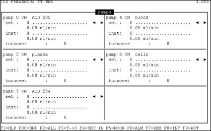
1.4.4Pumps
Pins 9 and 10 of relay RL 300 / P.C.B. LP 823-1 must be bridged to activate the pumps.
set: |
target speed in digits; see help menu for adjustment |
inst: |
actual speed in digits |
turnover: |
number of rotor revolutions |
cover closed: |
pump cover display: close - alarm |
1-16 Fresenius HemoCare COM.TEC 1/04.01 (TM)
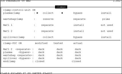
1.4.5Clamps
clamp-control-unit: clamp-control-unit display: on - off plasmaclamp: position of the plasma collection clamp wastebagclamp: position of the saline diversion clamp NaCl 1: position of the saline clamp in the inlet line
NaCl 2: position of the saline clamp in the return line spilloverclamp: position of the collection / return clamp
Fresenius HemoCare COM.TEC 1/04.01 (TM) |
1-17 |

1.4.6ASTEC IO1
Digital outputs and identifier:
test alarm 1: |
initiates the alarm test |
test alarm 2: |
cancels stored alarms |
dong: |
deep signal tone |
ding: |
high signal tone |
endclamp signal: |
opens the return clamp of the air detector if no alarm is pending and if |
alarm P: |
alarm P is set |
alarm-free if the output is set |
|
IL set: |
target value of the interface position |
IL automatic: |
interface controller |
ID rotorpulse: |
CAN identifier; do not change |
ID bloodpump: |
CAN identifier; do not change |
ID controlled pump: CAN identifier; do not change |
|
max pumpspeed: |
max. speed of the pump; do not change |
IL sensitivity: |
sensitivity of the interface |
IL scale factor: |
activation of the interface control by the PLS pump |
Analog inputs: |
|
temperature: |
temperature inside the centrifuge |
pressure 1: |
P3 pressure value |
pressure 2: |
inlet pressure value |
pressure 3: |
return pressure value |
pressure 4: |
reserve pressure channel value |
IL inst.: |
number of red holes of the interface detection |
setting PLS: |
target value of the PLS pump |
IL sensitivity: |
value of the control voltage |
1-18 Fresenius HemoCare COM.TEC 1/04.01 (TM)
Digital inputs: |
|
imbalance: |
imbalance alarm |
alarm press. 4 L: |
alarm pressure 4 too low |
alarm press 4 H: |
alarm pressure 4 too high |
alarm ACD high: |
alarm ACD ratio too high |
alarm substit.: |
alarm no replacement fluid |
mute: |
mute alarm tone generator |
alarm press. 3 L: |
alarm pressure P3 too low |
alarm press in H: |
alarm inlet pressure too high |
alarm press. out L: |
alarm return pressure too low |
air control: |
alarm air detector |
optical control: |
optical detector of the return clamp of the air detector |
alarm HB/HK: |
alarm hemolysis |
alarm press. in L: |
alarm inlet pressure too low |
alarm press. out H: |
alarm return pressure too high |
alarm press. 3 H: |
alarm pressure P3 too high |
alarm blood leak: |
alarm blood leak |
alarm SR-MC 1: |
alarm safety system, channel 1 |
alarm SR-MC 2: |
alarm safety system, channel 2 |
all alarms: |
all alarms are active (scanned during the alarm test) |
override(s): |
brief overriding of alarms (to fill the drip chamber) |
prime override: |
overriding of alarms during priming |
alarm alarm free: |
no alarm is pending |
alarm air actual: |
current air detector alarm |
alarm air memory: |
stored air detector alarm |
alarm ACD L: |
alarm - ACD ratio too low |
Fresenius HemoCare COM.TEC 1/04.01 (TM) |
1-19 |
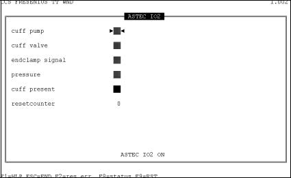
1.4.7ASTEC IO2
cuff pump: activates the single-needle pump
cuff valve: activates the single-needle valve (the end clamp must also be activated) endclamp signal: end clamp signal for single-needle control
pressure: indicates whether the pressure has been achieved cuff present: single-needle assembly P.C.B. LP-Z 175 present
1-20 Fresenius HemoCare COM.TEC 1/04.01 (TM)
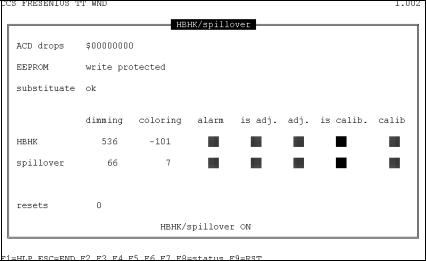
1.4.8HBHK / spillover
ACD drops: |
number of ACD drops |
EEPROM: |
indicates position of switch S1 / LP 867 |
substituade: |
status of substituate-empty detector |
HBHK: |
Hb/Hk detector |
spillover: |
spillover detector |
dimming: |
dimness of detector in digits |
coloring: |
coloring of detector in digits |
alarm: |
Alarm Hb/Hk or Spillover |
is adj.: |
lights after adjustment of the reference value |
adj.: |
lights during adjustment of the reference value |
is calib.: |
lights after calibration |
calib: |
lights during calibration |
Fresenius HemoCare COM.TEC 1/04.01 (TM) |
1-21 |

1.4.9CCD camera
loop control: |
– |
chamberlight: |
chamber light on - off |
mirrorlight: |
mirror light on - off |
initsearch: |
initialisation phase on - off |
automatic: |
automatic position test on - locked |
holeskew: |
hole skew, camera trigger |
startpixel: |
start pixel, interface window |
resetcounter: |
number of camera resets |
edgepixelval.: |
– |
ADC ref. low: |
reference voltage low |
ADC ref. high: |
reference voltage high |
lighttime ml.: |
mirror light exposure time |
lighttime cl.: |
chamber light exposure time |
errorbyte: |
internal display error counter |
set. line: |
target interface value |
interfaceline: |
actual interface value |
pmp max.: |
– |
set. pmp: |
– |
1-22 Fresenius HemoCare COM.TEC 1/04.01 (TM)
Table of Contents
2 Repair / Adjustment / Maintenance
Chapter |
|
Page |
2.1 |
Verification of the Interface Detection ........................................................................ |
2-5 |
2.1.1 |
Verification of the Optical Sensor ................................................................................... |
2-6 |
2.1.2 |
Verification of the 8 Hole Pulses ..................................................................................... |
2-7 |
2.1.3 |
Verification of the Interface Sensitivity of the 8 Hole Pulses ......................................... |
2-9 |
2.1.4 |
Verification of the C5 Interface Detection ....................................................................... |
2-10 |
2.2 |
Adjustment of the Interface Detection ........................................................................ |
2-12 |
2.2.1 |
Adjustment of the Optical Sensor ................................................................................... |
2-13 |
2.2.2 |
Basic Adjustment of the Camera and the Lighting Unit ................................................. |
2-14 |
2.2.3 |
Precision Adjustment of the Camera and the Lighting Unit ........................................... |
2-15 |
2.2.4 |
Adjustment of the 8 Hole Pulses (Basic Adjustment C5 Detection) .............................. |
2-17 |
2.2.5 |
Adjustment of the Interface Sensitivity of the 8 Hole Pulses ......................................... |
2-18 |
2.2.6 |
Adjustment of the C5 Interface Detection ....................................................................... |
2-19 |
2.3 |
C5 Interface Sensitivity ................................................................................................ |
2-22 |
2.3.1 |
Verification of the C5 Interface Sensitivity ...................................................................... |
2-22 |
2.3.2 |
Adjustment of the C5 Interface Sensitivity ...................................................................... |
2-23 |
2.4 |
Verification of the C5 Illuminance ............................................................................... |
2-24 |
2.5 |
Inlet Pressure Monitor .................................................................................................. |
2-26 |
2.5.1 |
Verification of the Gain ................................................................................................... |
2-26 |
2.5.2 |
Verification of the Alarm Limits ....................................................................................... |
2-26 |
2.5.3 |
Adjustment of the Gain ................................................................................................... |
2-27 |
2.5.4 |
Adjustment of the Alarm Limits ....................................................................................... |
2-29 |
2.6 |
Outlet Pressure Monitor ............................................................................................... |
2-31 |
2.6.1 |
Verification of the Gain ................................................................................................... |
2-31 |
2.6.2 |
Verification of the Alarm Limits ....................................................................................... |
2-31 |
2.6.3 |
Adjustment of the Gain ................................................................................................... |
2-32 |
2.6.4 |
Adjustment of the Alarm Limits ....................................................................................... |
2-34 |
2.7 |
P3 Monitor ..................................................................................................................... |
2-36 |
2.7.1 |
Verification of the Gain ................................................................................................... |
2-36 |
2.7.2 |
Verification of the Alarm Limits ....................................................................................... |
2-36 |
2.7.3 |
Adjustment of the Gain ................................................................................................... |
2-37 |
2.7.4 |
Adjustment of the Alarm Limits ....................................................................................... |
2-39 |
2.8 |
Operating Voltages / Battery Voltage ......................................................................... |
2-41 |
2.8.1 |
Verification ...................................................................................................................... |
2-41 |
2.9 |
Air Detector ................................................................................................................... |
2-42 |
2.9.1 |
Verification ...................................................................................................................... |
2-42 |
2.9.2 |
Adjustment ...................................................................................................................... |
2-43 |
2.10 |
Optical Detector in Air Detector .................................................................................. |
2-44 |
2.10.1 |
Verification ...................................................................................................................... |
2-44 |
2.10.2 |
Calibration of the Optical Detector .................................................................................. |
2-44 |
Fresenius HemoCare COM.TEC 1/04.01 (TM) |
2-1 |
Chapter |
|
Page |
2.11 |
Hb/Hct Detector ............................................................................................................. |
2-45 |
2.11.1 |
Verification ...................................................................................................................... |
2-45 |
2.11.2 |
Adjustment ...................................................................................................................... |
2-46 |
2.12 |
Spillover Detector ......................................................................................................... |
2-47 |
2.12.1 |
Verification ...................................................................................................................... |
2-47 |
2.12.2 |
Adjustment ...................................................................................................................... |
2-48 |
2.13 |
Substituate-Empty Detector ........................................................................................ |
2-49 |
2.18.1 |
Verification ...................................................................................................................... |
2-49 |
2.13.2 |
Adjustment ...................................................................................................................... |
2-50 |
2.14 |
Gap Width of Outlet Clamp .......................................................................................... |
2-51 |
2.14.1 Verification of Gap Width ................................................................................................ |
2-51 |
|
2.14.2 Verification of Line Occlusion ......................................................................................... |
2-51 |
|
2.14.3 |
Adjustment ...................................................................................................................... |
2-51 |
2.15 |
Line Pumps .................................................................................................................... |
2-52 |
2.15.1 |
Verification ...................................................................................................................... |
2-52 |
2.15.2 Verification of the 5 Line Pumps ..................................................................................... |
2-53 |
|
2.15.3 Cleaning of the Pump Rotors and the Pump Beds ........................................................ |
2-53 |
|
2.15.4 Adjustment of the Pump Rotors Nr. 4, 5, 6, 7 ................................................................. |
2-54 |
|
2.15.5 |
Final Check ..................................................................................................................... |
2-54 |
2.16 |
Clamps ........................................................................................................................... |
2-55 |
2.16.1 Verification of the Occlusion Pressure of the Clamps ................................................... |
2-56 |
|
2.17 |
Centrifuge Door ............................................................................................................. |
2-57 |
2.17.1 |
Removing the Door ......................................................................................................... |
2-57 |
2.17.2 Removing the Door Frame (Chassis) and the Pivot Bearing ......................................... |
2-57 |
|
2.17.3 |
Adjustment ...................................................................................................................... |
2-58 |
2.18 |
Door Switch ................................................................................................................... |
2-59 |
2.18.1 |
Verification ...................................................................................................................... |
2-59 |
2.18.2 |
Removal / Installation ..................................................................................................... |
2-60 |
2.18.3 |
Adjustment ...................................................................................................................... |
2-60 |
2.19 |
Centrifuge Motor Carbon Brushes .............................................................................. |
2-61 |
2.19.1 |
Verification ...................................................................................................................... |
2-61 |
2.20 |
Single Needle / Cuff Control ........................................................................................ |
2-62 |
2.20.1 |
Verifications .................................................................................................................... |
2-62 |
2.20.2 |
Adjustment ...................................................................................................................... |
2-63 |
2.21 |
Removal and Installation of the Centrifuge Rotor .................................................... |
2-64 |
2.21.1 Removal of the Centrifuge Rotor .................................................................................... |
2-65 |
|
2.21.2 Installation of the Centrifuge Rotor ................................................................................. |
2-66 |
|
2.22 |
Tightening the Belts in the Rotor ................................................................................ |
2-68 |
2.21.1 |
Verification ...................................................................................................................... |
2-68 |
2.22.2 |
Adjustment ...................................................................................................................... |
2-68 |
2.23 |
Brake .............................................................................................................................. |
2-69 |
2.23.1 |
Removal / Installation ..................................................................................................... |
2-69 |
2.23.2 |
Adjustment ...................................................................................................................... |
2-69 |
2-2 Fresenius HemoCare COM.TEC 1/04.01 (TM)
Loading...