


 Loading...
TECHNICAL MANUAL
TECHNICAL
MANUAL
OPTIMA PT-VS-ST
From Serial N° 18180100 till ...
Revision table
TM Optima PT-VS-ST_en : ref NT1741
Date |
Revision |
Chapter |
Description |
|
|
|
|
03/04/03 |
0 |
All index "a" |
création |
|
|
|
|
20/08/07 |
1 |
Index "b" |
New EMC standard, spare parts up date |
|
|
|
|
|
|
|
|
|
|
|
|
|
|
|
|
|
|
|
|

1 Presentation...................................................................................................... |
|
7 |
1.1 |
General presentation ............................................................................. |
7 |
1.2 |
Operation diagram ................................................................................. |
8 |
1.3 |
Precautions for use................................................................................ |
9 |
1.4 |
Operation safety ..................................................................................... |
9 |
1.5 |
Technical characteristics ...................................................................... |
9 |
1.5.1 |
Electrical details ......................................................................................................... |
9 |
1.5.2 |
Electronic details ........................................................................................................ |
9 |
1.5.3 |
Mechanical details...................................................................................................... |
9 |
1.5.4 |
Conformity and norms.............................................................................................. |
10 |
2 Description and operation............................................................................. |
11 |
|
2.1 Physical description ............................................................................ |
11 |
|
2.1.1 Display board and front panel .................................................................................. |
12 |
|
2.1.2 |
The CPU board ........................................................................................................ |
14 |
2.1.3 The power supply board and battery........................................................................ |
17 |
|
2.2 Operational description ....................................................................... |
19 |
|
2.2.1 Tube check and maintenance sub-assembly........................................................... |
19 |
|
2.2.2 |
Pumping sub-assembly............................................................................................ |
19 |
2.2.3 |
External connection sub-assembly .......................................................................... |
19 |
3 Description of the menus .............................................................................. |
21 |
||
3.1 |
Parameter configuration menu ........................................................... |
21 |
|
3.1.1 Access to the menu.................................................................................................. |
23 |
||
3.1.2 |
SAV1, preventive maintenance configuration ....................................................... |
24 |
|
3.1.3 |
SAV2, tube selection configuration ....................................................................... |
24 |
|
3.1.4 |
SAV3, "Beep" ........................................................................................................ |
25 |
|
3.2 |
Calibration menu .................................................................................. |
27 |
|
3.3 |
After-Sales Service test menu............................................................. |
29 |
|
4 Preventive maintenance ................................................................................ |
31 |
||
4.1 |
Recommendations ............................................................................... |
31 |
|
4.2 |
Maintenance schedule ......................................................................... |
31 |
|
4.2.1 |
Preventive maintenance........................................................................................... |
31 |
|
4.2.2 |
Quality control .......................................................................................................... |
31 |
|
4.3 |
Checks................................................................................................... |
33 |
|
4.3.1 |
Accessing the tests .................................................................................................. |
33 |
|
4.3.2 |
Visual check ............................................................................................................. |
33 |
|
4.3.3 Operating period and maintenance date.................................................................. |
34 |
||
4.3.4 |
Indicator lights test ................................................................................................... |
34 |
|
4.3.5 |
Keyboard check ....................................................................................................... |
35 |
|
4.3.6 |
Battery voltage check............................................................................................... |
35 |
|
4.3.7 Checking the last 10 alarms..................................................................................... |
35 |
||
|
|
|
|
Optima_PT-VS-ST_enTDM.fm |
|
3 |
|
|
|
|
|

4.3.8 |
Checking the total operating period ......................................................................... |
37 |
4.3.9 |
Checking the analogue sensor input........................................................................ |
37 |
4.3.10 |
Checking the software version ................................................................................. |
38 |
4.3.11 |
Checking the motor clamp (only Optima VS) .......................................................... |
38 |
4.3.12 |
Checking the calibration values ............................................................................... |
39 |
4.3.13 |
Checking the infusion motor..................................................................................... |
39 |
4.3.14 |
Checking the last 10 events before a locking alarm or error.................................... |
40 |
4.3.15 |
Checking the pressure alarm limit............................................................................ |
40 |
4.3.16 |
Flow rate check ........................................................................................................ |
41 |
4.3.17 |
Air detector check .................................................................................................... |
41 |
4.3.18 |
Battery autonomy check........................................................................................... |
41 |
4.3.19 |
Continuity test .......................................................................................................... |
42 |
4.3.20 |
Contrast check ......................................................................................................... |
42 |
4.3.21 |
Timestamp check ..................................................................................................... |
42 |
4.3.22 |
Quality Control Certificate ........................................................................................ |
43 |
4.4 Cleaning and disinfecting ................................................................... |
45 |
|
4.5 Storage.................................................................................................. |
46 |
|
5 |
Troubleshooting.............................................................................................. |
47 |
|
5.1 Breakdown guide ................................................................................. |
47 |
|
5.2 Error messages ................................................................................... |
51 |
6 |
Intervention procedures................................................................................. |
55 |
|
N∞1, Procedure: CPU board ....................................................................... |
57 |
|
N∞2, Procedure: Display board .................................................................. |
61 |
|
N∞3, Procedure: Pumping system ............................................................. |
65 |
|
N∞4, Procedure: LCD display .................................................................... |
69 |
|
N∞5, Procedure: Air detector board........................................................... |
73 |
|
N∞6, Procedure: Pressure sensor.............................................................. |
77 |
|
N∞7, Procedure: OCS clamp motor (if OCS is present) ........................... |
81 |
|
N∞8, Procedure: Power supply board ....................................................... |
85 |
|
N∞9, Procedure: Battery ............................................................................. |
87 |
|
N∞10, Procedure: Front cover, base and angle bracket .......................... |
89 |
7 |
Calibration ....................................................................................................... |
93 |
|
7.1 Calibration procedure.......................................................................... |
93 |
|
7.1.1 Access to the calibrations ........................................................................................ |
93 |
|
7.1.2 EtAL.1 Door calibration....................................................................................... |
94 |
|
7.1.3 EtAL.2 Calibration of the flow rate corrective coefficient .................................... |
95 |
|
7.1.4 EtAL.9 Calibrating the upstream and downstream pressure sensors ................ |
96 |
|
44 |
Optima_PT-VS-ST_enTDM.fm |
|
|
|

8 Spare parts catalogue.................................................................................... |
99 |
|
8.1 |
Upper cover .......................................................................................... |
99 |
8.2 |
Base..................................................................................................... |
101 |
8.3 |
Optima pump angle bracket .............................................................. |
103 |
Optima_PT-VS-ST_enTDM.fm |
5 |
|
|

|
66 |
Optima_PT-VS-ST_enTDM.fm |
|
|
|

1Presentation
1.1General presentation
The Optima pump is a new pump based on the same pumping mechanism as the MVP pump. It is used for infusion of intravenous agents.
There are three types of the Optima pump:
PT: for standard PVC tubes with a drop detector.
VS: for standard PVC tubes. The drop detector is optional. The pump is equipped with an automatic occlusion checking system (OCS).
ST: for silicon tubes equipped with a drop detector.
The Optima pump has its own control keyboard and distinct displays. It has an internal battery which ensures a minimum autonomy of 4 hours for a flow rate of 125 ml/h.
A choice of easily accessible configurations enables optimal use of the functions according to the needs of each department.
Presentation
optima01_002b_en.fm |
7 |
|
|

1.2 Operation diagram
Presentation |
|
8 |
optima01_002b_en.fm |

1.3 Precautions for use
The symbol ! which appears on the device’s condensed user instructions recommends a complete reading of the user instructions, in accordance with norm EN 60 601-1.
Fresenius Vial cannot, in any circumstances, be held responsible for any medical or other problem due to incorrect use of the device.
Kindly consult the user manual for more details.
1.4 Operation safety
As soon as it is in operation, the device ensures permanent surveillance of its functions. Any internal fault or any procedural anomaly is immediately detected. Nevertheless, abnormal functioning of the device, without a defined cause, must always be brought to the attention of the qualified staff in your establishment or our After-sales Service.
The Optima pump contains an internal battery which ensures normal functioning during a mains power cut. In addition, two fuses protect the affected mains area.
1.5Technical characteristics
1.5.1Electrical details
!External power supply: 100 - 240 Vac.
!Max. consumption: 50 VA.
!Battery: 6 V - 2.7/ 3 Ah - NIMH.
!Fuse: 2 x 630 mA T IEC 127.
1.5.2 Electronic details
The Optima volumetric pump has 4 electronic boards:
!CPU board
!Display board
!Power supply board
!Air detector board
1.5.3 Mechanical details
!Dimensions: H x L x W: 135 x 175 x 145 mm.
!Weight: approx. 2.9 kg
Presentation
optima01_002b_en.fm |
9 |
|
|
|
|
|
1.5.4 Conformity and norms |
|
|
|
|
|
|
|
|
|
|
|
Conform to the 93/42/EEC Medical Directive. |
IP31 Protection against |
|
0459 |
|
splashing liquid. |
|||
Safety of Electro |
Conform to EN/IEC 60601-1 and EN/IEC 60601-2-24. |
|
Protection against |
||
Medical |
|
|
leakage current: CF |
||
Equipements |
|
type. |
|||
EMC |
Conform to EN/IEC 60601-1-2 (second index) |
|
Protection against |
||
(ElectroMagnetic |
and EN/IEC 60601-2-24. |
|
electric shocks: class I. |
||
Compatibility) |
|
|
|
||
|
|
Direct Courant |
Equipotentiality |
|
Fonctionnal earth. |
|
|
|
|||
|
|
|
|
|
|
Detailed information concerning electromagnetic compatibility is available in the chapter "Guidance and manufactureris declaration on EMC" of the User Manual.
Presentation
|
10 |
optima01_002b_en.fm |
|
|
|
2Description and operation
2.1Physical description
Angle bracket |
|
|
Control panel |
|||||||||||
|
|
|
|
|
|
|
|
|
|
|
|
|
|
|
|
|
|
|
|
|
|
|
|
|
|
|
|
|
|
|
|
|
|
|
|
|
|
|
|
|
|
|
|
|
|
|
|
|
|
|
|
|
|
|
|
|
|
|
|
|
|
|
|
|
|
|
|
|
|
|
|
|
|
|
|
|
|
|
|
|
|
|
|
|
|
|
|
|
|
|
|
|
|
|
|
|
|
|
|
|
|
|
|
|
|
|
|
|
|
|
|
|
|
|
|
|
|
|
|
Air bubble |
Front cover |
Door |
Base |
detector |
|
|
|
The Optima pump is made out of a front cover, a base and an angle bracket.
!The front cover contains:
"a display board linked to the control panel,
"a CPU board,
"an air detector board,
"the OCS system if OCS is present.
!The base supports the door and contains:
"the pump body unit.
!The angle bracket contains:
"a power supply board,
"the battery.
optima02_002b_en.fm
Description and operation
11
Description and operation
12
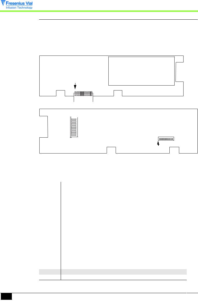
2.1.1 Display board and front panel
The display board is situated under the control panel and contains all the essential parts for the man-machine interaction:
!keyboard,
!synoptic and control indicators,
!7-segment displays,
!LCD screen.
Pin n°1
J1
Display board LCD screen side.

 Pin n°1
J2
J3
Pin n°1
Display board component side
This board is connected to the various equipment by means of connectors:
J1 connector to CPU board
Pin |
Signal |
Description |
1 |
5V |
Power supply |
|
|
|
2 |
VBAT |
Battery voltage |
3 |
GND |
|
4 |
MOSI-AFF |
Serial output |
5 |
GND |
|
6 |
MISO-AFF |
Serial input |
7 |
GND |
|
|
|
|
8 |
CLK-AFF |
Serial clock |
9 |
GND |
|
10 |
CSLCD |
LCD selection |
11 |
GND |
|
12 |
CSAFCL |
Display selected |
13 |
GND |
|
|
|
|
14 |
A0AFF |
LCD address |
15GND
16RESET/
17GND
optima02_002b_en.fm

J1 connector to CPU board
Pin |
Signal |
Description |
18 |
TON/OFF |
ON/OFF Signal |
19 |
VBAT |
Battery voltage |
20 |
5V |
Power supply |
J2 connector to LCD |
|
|
|
|
|
Pin |
Signal |
Description |
1 |
+ led |
VBAT + back light |
2 |
- led |
- back light |
3 |
+5V |
|
4 |
/RESET |
/RESET |
5 |
VSS |
Gnd |
6 |
LD7 |
Data’s writing |
7 |
R/W |
Gnd - Writing selection |
8 |
LD6 |
Data’s writing |
9 |
A0AFF |
LCD address |
10 |
LD5 |
Data’s writing |
11 |
LD4 |
Data’s writing |
12 |
LD3 |
Data’s writing |
13 |
LD2 |
Data’s writing |
14 |
LD1 |
Data’s writing |
15 |
LD0 |
Data’s writing |
16 |
Enable |
|
17 |
LCDCS2 |
Chip select |
18 |
/LCDCS1 |
Chip select |
J3 connector to keyboard |
|
|
|
|
|
Pin |
Signal |
Description |
1 |
COL2 |
Keyboard interface column |
2 |
COL1 |
Keyboard interface column |
3 |
COL0 |
Keyboard interface column |
4 |
Line 3 |
Keyboard interface |
5 |
Line 2 |
Keyboard interface |
6 |
Line1 |
Keyboard interface |
7 |
Line 0 |
Keyboard interface |
8 |
TON/OFF |
On/Off |
9CONTRÔLE
10GND
Description and operation
optima02_002b_en.fm |
13 |
|
|
Description and operation
14
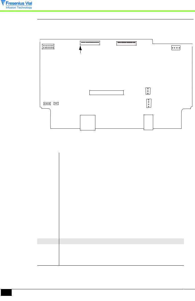
2.1.2 The CPU board
The CPU board contains a 80C32 micro-processor. It is connected to the display board by means of the J1 connector.
J1 |
J2 |
J4 |
J3
Pin n°1
J7
J6
J9 J10
J8
J11 |
J12 |
CPU board
Info: Pin 1 of connector J1 is opposite to that indicated by the CPU board screen printing.
J1 display board connector
Pin |
Signal |
Description |
1 |
5V |
Power supply |
2 |
VBAT |
Battery voltage |
3 |
GND |
|
|
|
|
4 |
MOSI-AFFl |
Serial output |
5 |
GND |
|
6 |
MISO-AFF |
Serial input |
7 |
GND |
|
8 |
CLK-AFF |
Serial clock |
9 |
GND |
|
|
|
|
10 |
CSLCD |
LCD selection |
11 |
GND |
|
12 |
CSAFCL |
Display selected |
13 |
GND |
|
14 |
A0AFF |
Address LCD |
15GND
16RESET/
17GND
18 |
GNDTON/OFF |
Signal ON/OFF |
19 |
VBAT |
Battery voltage |
20 |
5V |
Power supply |
optima02_002b_en.fm

J12 drip detector connector
Pin |
Signal |
Description |
1 |
Pulse-drip |
Low signal yield |
2GND
3GND
4 |
CDLED-drip |
Control LED 5V/ 40 mA |
J4 motor connector
Pin Description
1+Reel A
2- Reel A
3+Reel B
4- Reel B
J6 power supply connector
Pin |
Signal |
Description |
1 |
ALIM SECT |
Power supply |
2 |
GND |
|
3 |
ALIM EXT |
Not used |
J8 battery connector |
|
|
|
|
|
Pin |
Signal |
Description |
1 |
VBATNC |
+ Battery |
2 |
ANA-CTN |
Temperature sensor Output |
3 |
GND |
|
4 |
VBATNP |
+ Battery before thermal fuse |
J11 RS232 connector / Nurse call |
|
|
|
|
|
Pin |
Signal |
Description |
1 |
TxD-PC |
Data reception from PC |
2 |
RTS-PC |
Request to send from PC |
3 |
DTR-PC |
PC terminal ready |
4 |
RXD-PC |
Transmission of data to PC |
5 |
GND |
|
6 |
Nurse Call |
Normally open contact |
7 |
Nurse Call |
Common contact |
8 |
Nurse Call |
Normally closed contact |
J10 D.C. motor connector
Pin Description
1+ DC motor
2- DC motor
optima02_002b_en.fm
Description and operation
15

J2 sensors connector
Pin |
Signal |
Description |
1 |
GND |
|
|
|
|
2 |
/PRES_CLAMP |
CLAMP presence |
3 |
CD_CLAMP/ |
CLAMP detector power supply |
4 |
+AMPLI_AM |
Input + ampli sensor upstream pressure |
5 |
- ALIM_AM |
Upstream pressure sensor power supply return |
6 |
- AMPLI_AM |
Input - ampli upstream pressure sensor |
7 |
+ ALIM_AM |
Upstream pressure sensor power supply |
|
|
|
8 |
GND |
|
9 |
- |
Hall effect sensor power supply |
10 |
GND |
|
11 |
ANA_HALL |
Hall effect sensor output |
12 |
+ AMPLI_AV |
Input + ampli downstream pressure sensor |
13 |
- ALIM_AV |
Downstream pressure sensor power supply |
|
|
return |
|
|
|
14 |
- AMPLI_AV |
Input - ampli downstream pressure sensor |
15 |
+ ALIM_AV |
Downstream pressure sensor power supply |
16 |
GND |
|
17 |
ET OPTO |
State of sensor |
18 |
GND |
|
19 |
+5 V |
5 V power supply |
|
|
|
20 |
- |
Power supply sensor return |
J9 air detector connector |
|
|
|
|
|
Pin |
Description |
Description |
1 |
/TST |
Sensor test |
25V
3GND
4 |
/DETECT |
Air bubble detection |
Description and operation
|
16 |
optima02_002b_en.fm |
|
|
|
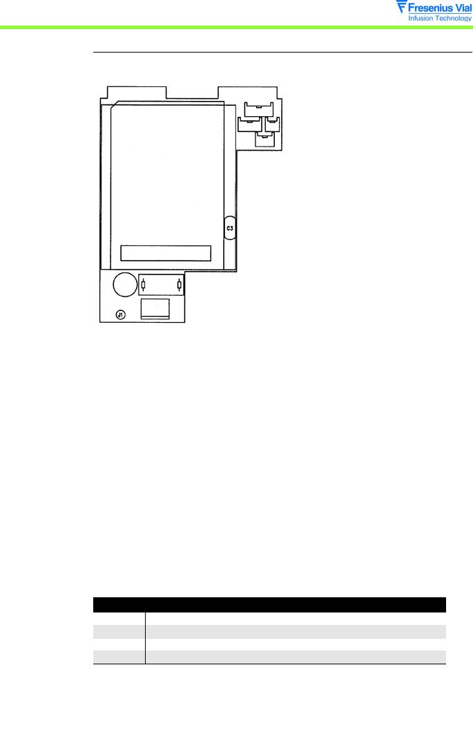
2.1.3 The power supply board and battery
The power supply board is positioned on the angle bracket. It supplies power to the electronic unit from the 230 VAC network. It also ensures a battery charge of 2.7/3 Ah.
J6
J4 J5
J3
U1
U2
C3 
Bars code
F2 L1
J2
J1 

Power supply board
This board is connected to the various parts by means of connectors. F2 is time-delayed fuses of 630 mAT.
J1 functional Earth connector
J2 Mains connector
Pin |
Description |
|
1 |
PH |
Phase (100 - 240 Vac) |
2 |
N |
Neutral (100 - 240 Vac) |
J3 power supply output connector |
|
|
|
|
|
Pin |
Description |
|
1 |
9V Sect |
9V output convertor AC/DC |
2 |
GND |
|
3 |
9V Ext |
9V external power supply not used |
J4 battery output connector to the CPU board
Pin Description
1+Vbat
2+Thermal sensor
3GND
4VBAT NP
optima02_002b_en.fm |
17 |
|
|
Description and operation

J6 battery input connector
Pin Description
1+ VBAT
2VBAT NP
3+ Thermal sensor
4- Thermal sensor
5GND
Description and operation
|
18 |
optima02_002b_en.fm |
|
|
|

2.2 Operational description
From an operational point of view, the Optima pump is made up of 3 sub-assemblies:
!a sub-assembly to maintain to check the correct positioning of the tube,
!a motorisation sub-assembly,
!an external connection sub-assembly.
2.2.1 Tube check and maintenance sub-assembly
The tube is positioned along the front part and held in place by the door.
The front part is equipped with four detection systems:
!a detector to check the closed /open position of the door,
!an ultra-sound detector to detect the presence of air bubbles in the tube.
!The pressure detection is ensured by two piezo-resistant sensors.
2.2.2 Pumping sub-assembly
The pumping sub-assembly contains the peristaltic pumping mechanism.
The mechanism is made up of a camshaft that creates a wave-like movement in a bank of 14 ’fingers’. The displacement of these ’fingers’ is controlled by the CPU board, while turning it displaces the liquid at the programmed flow rate.
The cam shaft is driven by a stepper-motor and a reduction gearbox assembly via a toothed belt.
An optical disc attached to the end of the cam shaft controls its rotation.
2.2.3 External connection sub-assembly
The Optima contains two connectors located at the rear of the lower case:
!an RS 232 connector/Nurse call,
!a connector dedicated to the drip detector.
Description and operation
optima02_002b_en.fm |
19 |
|
|

Description and operation
|
20 |
optima02_002b_en.fm |
|
|
|
3 Description of the menus
3.1 Parameter configuration menu
The configuration menu adapts the Optima to the particular needs of each department. It accesses the menus that customise the infusion parameters.
Fresenius Vial recommends the presence of its qualified staff, or a member of your Technical Department, who will assist you in implementing the configuration procedures you wish to select.
The configuration mode is activated by holding down the "MODE" key when the device is switched on.
The following menus are displayed:
!User setting,
!Wards setting,
!Maintenance.
Each menu consists of sub-menus. The sub-menus can be accessed by using the "START" key.
To access some of the sub-menus, you need to type in an access code. This code can be defined and/or de-activated in the Service configuration mode. As long as the device is kept switched on, the code does not need to be keyed in again.
Main Menu |
Key in code |
Sub-menu |
Sub-menu |
|
|
|
|
User setting |
Code XXXX |
|
|
|
|
|
|
|
|
User setting menu |
|
|
|
|
|
Wards setting |
Code 0200 |
|
|
|
|
|
|
|
|
Wards setting menu |
|
|
|
|
|
Maintenance |
This code will be communicated at the end of the maintenance |
||
|
technician training. |
|
|
|
|
|
|
|
|
Test |
|
|
|
|
|
|
|
|
Maintenance tests menu |
|
|
|
|
|
|
After-sales configuration |
|
|
|
|
|
|
|
|
Maintenance configuration |
|
|
|
menu |
|
|
|
|
|
|
Calibration |
|
|
|
|
|
|
|
|
Calibration menu |
|
|
|
|
Description of the menus
optima03.1_001b_en.fm |
21 |
|
|
Maintenance
Description of the menus
22
Test |
TEst.1 |
operating period and maintenance date |
|
|
|
|
TEst.2 |
LED, LCD screen, 7-segment display and buzzer test |
|
|
|
|
TEst.3 |
keyboard test |
|
|
|
|
TEst.4 |
display’s the battery voltage |
|
|
|
|
TEst.5 |
display’s the last 10 alarms codes |
|
|
|
|
TEst.6 |
display’s the total running time |
|
|
|
|
TEst.9 |
display’s the analogue sensor values |
|
|
|
|
TEst.A |
display’s the software version |
|
|
|
|
TEst.C |
clamping motor test |
|
|
|
|
TEst.E |
display’s the calibration values |
|
|
|
|
TEst.F |
infusion motor test |
|
|
|
|
TEst.J |
display’s the code last 10 alarm codes before error |
|
|
|
Configuration |
SAV.1 |
preventive maintenance |
|
|
|
|
SAV.2 |
tube selection |
|
|
|
|
SAV.3 |
Beep |
|
|
|
Calibration |
EtaL.1 |
door calibration |
|
|
|
|
EtaL.2 |
corrective infusion coefficient |
|
|
|
|
EtaL.9 |
upstream and downstream pressure sensors |
|
|
calibration |
|
|
|
The maintenance menu is reserved for qualified staff only.
optima03.1_001b_en.fm
3.1.1 Access to the menu
Key |
Function |
|
ON switches on the device. |
|
OFF switches off the device and exits the configuration mode when |
|
pressed for more than three seconds. |
|
SILENCE ALARM |
|
MODE accesses the configuration mode. |
|
The selection keys scroll through the numbers and letters, the tenths, |
|
units and tens values. |
|
Activate or de-activate choices. |
|
ENTER moves the cursor. |
|
START validates a selection. |
|
STOP cancels the current configuration. |
Activate the After-Sales Service test menu.
! Keep the "MODE" button pressed, during the device switch on.
" The various menus are displayed.
!Select the "Maintenance" menu and confirm.
! Type in the access code and confirm. ! Select "Sav" and confirm.
! Use the selection keys to scroll through the various tests on the LCD display.
Description of the menus
optima03.1_001b_en.fm |
23 |
|
|
Description of the menus
24
3.1.2 SAV1, preventive maintenance configuration
!SAV1, press "START".
"The running time since the last maintenance in hours and the date are displayed on the LCD screen.
" To move the cursor use the enter key.
" Use the selection keys to modify a field.
"By validating once again, the new running time and date are memorised and you may return to the After-sales Service menu.
By pressing "STOP" you can cancel the modification and return to the Aftersales Service configuration menu.
You can exit the configuration mode at any time by pressing the "OFF" key.
3.1.3 SAV2, tube selection configuration
!SAV2, press "START".
" The list of available tubes is displayed on the LCD screen.
The tubes which have already been calibrated for pressure are marked with a "v".
"Select the tube using the keys.
"Press "START" to save the tube selection.
"When the device is switched on, the selected tube will appear on the display unit.
By pressing "STOP", the modification is cancelled and you can return to the After-sales Service configuration menu.
You can exit the configuration mode at any time by pressing the "OFF" key.
optima03.1_001b_en.fm
3.1.4 SAV3, "Beep"
This option is available on Optima pump equipped with software version 1.8e minimum.
! SAV3, press "START".
! + 10 s. (not activated)
! + 0 s. (activated)
" Select your choice using the key.
# 10 s: the audible alarm "Beep" is triggered every 10 seconds.
#0 s: the audible alarm "Beep" is triggered every 0 second.
"Press "START" to record your selection.
By pressing "STOP", the modification is cancelled and you can return to the
After-sales Service configuration menu.
You can exit the configuration mode at any time by pressing the "OFF" key.
Description of the menus
optima03.1_001b_en.fm |
25 |
|
|

Description of the menus
|
26 |
optima03.1_001b_en.fm |
|
|
|

3.2 Calibration menu
The calibration menu is reserved for qualified staff only. Its access is protected by a secret code. To find out about the operating mode for the various calibrations, refer to the "Calibrations" chapter.
This menu enables manual calibration of:
!ETAL.1: the door,
!ETAL.2: the corrective coefficient for the infusion flow rate by tube type,
!ETAL.9: the upstream and downstream pressure sensors.
Description of the menus
optima03.3_001b_en.fm |
27 |
|
|

Description of the menus
|
28 |
optima03.3_001b_en.fm |
|
|
|
3.3 After-Sales Service test menu
The After-Sales Service test menu is reserved for qualified personnel. It enables a series of checks that can be carried out on the Optima pump to confirm it is operating correctly. (See chapter "Checks"). These must be carried out each time parts are replaced.
The After-Sales Service tests can also be carried out more quickly and simply from a PC using our maintenance software. (Contact our After-Sales Service department.)
The Service test menu contains a series of 17 tests or checks:
!tESt.1: operation period and maintenance date display
!tESt.2: indicator lights test
!tESt.3: keyboard test
!tESt.4: battery voltage test
!tESt.5: display’s the last 10 alarms codes
!tESt.6: display’s the total operating period
!tESt.9: display’s the analogue sensor values
!tESt.A: display’s the software version
!tESt.C: clamping motor test (only Optima VS)
!tESt.E: display’s the calibration values
!tESt.f: infusion motor test
!tESt.J: display’s the last 10 alarm codes before error
A log of more than 760 time-stamped events can be consulted using our maintenance software "VP Control". (Contact our After-Sales Service department.)
Description of the menus
optima03.4_002b_en.fm |
29 |
|
|

Description of the menus
|
30 |
optima03.4_002b_en.fm |
|
|
|
Loading...