


GB
IT
FR
DE
TR
CZ
FI
Instructions for use and installation
Istruzioni per l’uso e l’installazione
Cappa
Mode d’emploi et installation
Bedienungsanleitung und Einrichtung
Dunstabzugshaube
Kullanım ve montaj talimatları
Davlumbaz
Uživatelská Pøíruèka
Odsavač par
Asennus-, käyttöja hoito-opas
Liesituuletin
FFC 905-P XS
FFC 905-P XS CH
FFC 1005 XS

INDEX |
EN |
RECOMMENDATIONS AND SUGGESTIONS ..................................................................................................................... |
4 |
CHARACTERISTICS ............................................................................................................................................................. |
5 |
INSTALLATION...................................................................................................................................................................... |
7 |
USE ...................................................................................................................................................................................... |
10 |
MAINTENANCE ................................................................................................................................................................... |
11 |
INDICE |
IT |
CONSIGLI E SUGGERIMENTI............................................................................................................................................ |
12 |
CARATTERISTICHE............................................................................................................................................................ |
13 |
INSTALLAZIONE ................................................................................................................................................................. |
15 |
USO...................................................................................................................................................................................... |
18 |
MANUTENZIONE ................................................................................................................................................................ |
19 |
SOMMAIRE |
FR |
CONSEILS ET SUGGESTIONS.......................................................................................................................................... |
20 |
CARACTERISTIQUES......................................................................................................................................................... |
21 |
INSTALLATION.................................................................................................................................................................... |
23 |
UTILISATION ....................................................................................................................................................................... |
26 |
ENTRETIEN ......................................................................................................................................................................... |
27 |
INHALTSVERZEICHNIS |
DE |
EMPFEHLUNGEN UND HINWEISE ................................................................................................................................... |
28 |
CHARAKTERISTIKEN ......................................................................................................................................................... |
29 |
MONTAGE ........................................................................................................................................................................... |
31 |
BEDIENUNG........................................................................................................................................................................ |
34 |
WARTUNG........................................................................................................................................................................... |
35 |
IÇERIKLER |
TR |
TAVSIYELER VE ÖNERILER.............................................................................................................................................. |
36 |
ÖZELLIKLER........................................................................................................................................................................ |
37 |
MONTAJ............................................................................................................................................................................... |
39 |
KULLANIM ........................................................................................................................................................................... |
42 |
BAKIM .................................................................................................................................................................................. |
43 |
OBSAH |
CZ |
RADY A DOPORUČENÍ ...................................................................................................................................................... |
44 |
HLAVNÍ PARAMETRY......................................................................................................................................................... |
45 |
INSTALACE ......................................................................................................................................................................... |
47 |
POUŽITÍ ............................................................................................................................................................................... |
50 |
ÚDRŽBA............................................................................................................................................................................... |
51 |
2

SISÄLTÖ |
FI |
OHJEET JA SUOSITUKSET |
............................................................................................................................................... 52 |
MITAT JA OSAT .................................................................................................................................................................. |
53 |
ASENNUS ............................................................................................................................................................................ |
55 |
KÄYTTÖ ............................................................................................................................................................................... |
58 |
HUOLTO .............................................................................................................................................................................. |
59 |
3
RECOMMENDATIONS AND SUGGESTIONS
The Instructions for Use apply to several versions of this appliance. Accordingly, you may find descriptions of individual features that do not apply to your specific appliance.
INSTALLATION
• The manufacturer will not be held liable for any damages resulting from incorrect or improper
installation.
• The minimum safety distance between the cooker top and the extractor hood is 650 mm (some models can be installed at a lower height, please refer to the paragraphs on working dimensions and installation).
• Check that the mains voltage corresponds to that indicated on the rating plate fixed to the inside of the hood.
• For Class I appliances, check that the domestic power supply guarantees adequate earthing. Connect the extractor to the exhaust flue through a pipe of minimum diameter 120 mm. The route of the flue must be as short as possible.
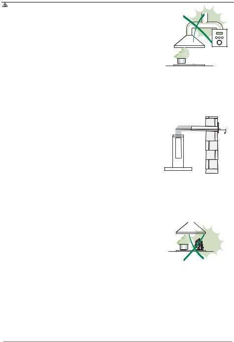
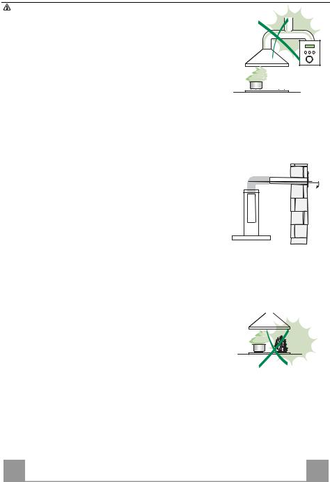
•Do not connect the extractor hood to exhaust ducts carrying combustion fumes (boilers, fireplaces, etc.).
•If the extractor is used in conjunction with non-electrical appliances (e.g. gas burning appliances), a sufficient degree of aeration must be guaranteed in the room in order to prevent the backflow of exhaust gas. The kitchen must have an opening communicating directly with the open air in order
to guarantee the entry of clean air. When the cooker hood is used in conjunction with appliances |
|
supplied with energy other than electric, the negative pressure in the room must not exceed 0,04 |
|
mbar to prevent fumes being drawn back into the room by the cooker hood. |
2° |
• In the event of damage to the power cable, it must be replaced by the manufacturer or by the |
|
technical service department, in order to prevent any risks. |
|
• If the instructions for installation for the gas hob specify a greater distance specified above, this has |
|
to be taken into account. Regulations concerning the discharge of air have to be fulfilled. |
|
USE
•The extractor hood has been designed exclusively for domestic use to eliminate kitchen smells.
•Never use the hood for purposes other than for which it has been designed.
•Never leave high naked flames under the hood when it is in operation.
•Adjust the flame intensity to direct it onto the bottom of the pan only, making sure that it does not engulf the sides.
•Deep fat fryers must be continuously monitored during use: overheated oil can burst into flames.
•Do not flambè under the range hood; risk of fire
•This appliance is not intended for use by persons (including children) with reduced physical, sensory or mental capabilities, or lack of experience and knowledge, unless they have been given supervision or instruction concerning use of the appliance by a person responsible for their safety.
•Children should be supervised to ensure that they do not play with the appliance.
•“ CAUTION: Accessible parts may become hot when used with cooking appliances.”.
MAINTENANCE
• Switch off or unplug the appliance from the mains supply before carrying out any maintenance work.
• Clean and/or replace the Filters after the specified time period (Fire hazard).
• Clean the hood using a damp cloth and a neutral liquid detergent.
The symbol  on the product or on its packaging indicates that this product may not be treated as household waste. Instead it shall be handed over to the applicablecollectionpointfortherecyclingofelectricalandelectronicequipment.Byensuringthisproductisdisposedofcorrectly,youwillhelppreventpotentialnegative consequencesfortheenvironmentandhumanhealth,whichcouldotherwisebecausedbyinappropriatewastehandlingofthisproduct.Formoredetailedinformation aboutrecyclingofthisproduct,pleasecontactyourlocalcityoffice,yourhouseholdwastedisposalserviceortheshopwhereyoupurchasedtheproduct.
EN |
|
4 |
|
4 |

CHARACTERISTICS
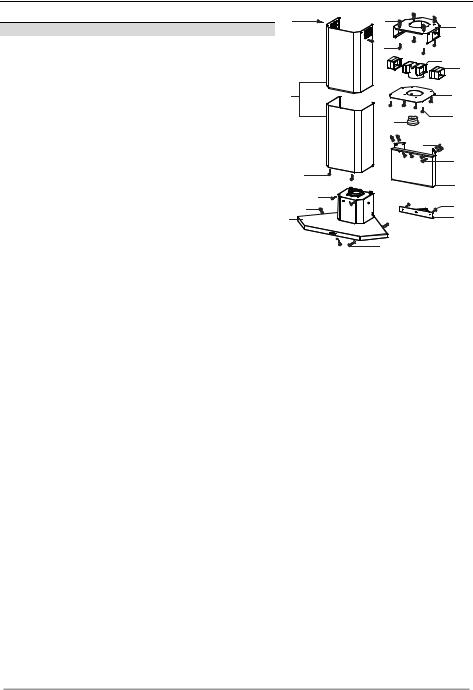
Components
Ref. Q.ty Product components
11 Cooker hood complete with control unit, lights, blower unit, filters
2 |
1 |
Telescopic chimney comprised of: |
2.1 |
1 |
upper chimney |
2.2 |
1 |
lower chimney |
9 |
1 |
reducer flange ø 150-120 mm |
14.1 |
2 |
air outlet connection extension |
15 |
1 |
air outlet connection |
Ref. |
Q.ty |
Installation components |
7.1 |
1 |
Lower corner spacer |
7.2 |
1 |
Hood fixing support piece |
7.3 |
1 |
Air outlet connection support piece |
7.4 |
1 |
Upper chimney support piece |
11 |
10 |
Wall plugs ø 8 |
12a |
10 |
Screws 4,2 x 44,4 |
12b |
2 |
Screws 4,2 x 12,7 |
12c |
12 |
Screws 2,9 x 9,5 |
|
Q.ty |
Documentation |
|
1 |
Instruction booklet |
12c |
11 |
|
7.4 |
|
12a |
|
15 |
|
14.1 |
2.1 |
|
2 |
7.3 |
2.2 |
12c |
|
9 |
|
11 |
|
12a |
12c |
|
|
7.2 |
|
12b |
11 |
12c |
|
|
1 |
7.1 |
|
|
|
12a |
EN |
|
5 |
|
5 |
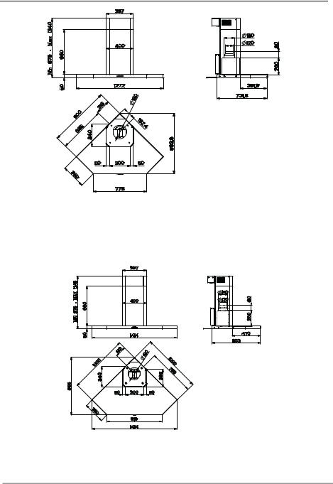
Dimensions
EN |
|
6 |
|
6 |
INSTALLATION
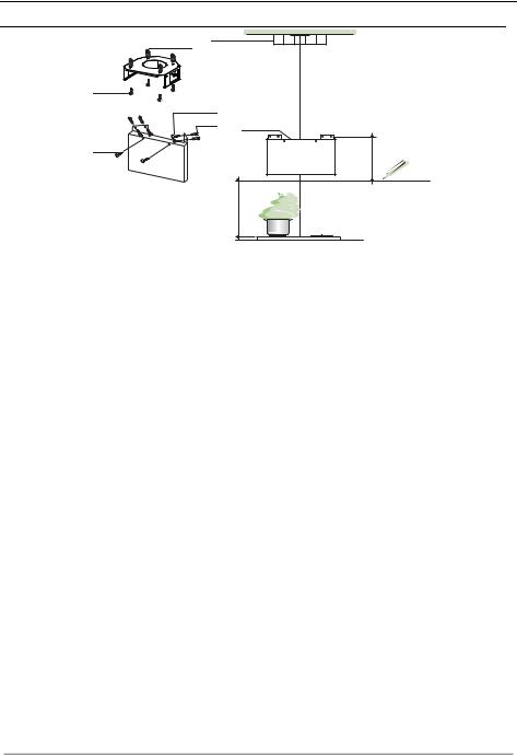
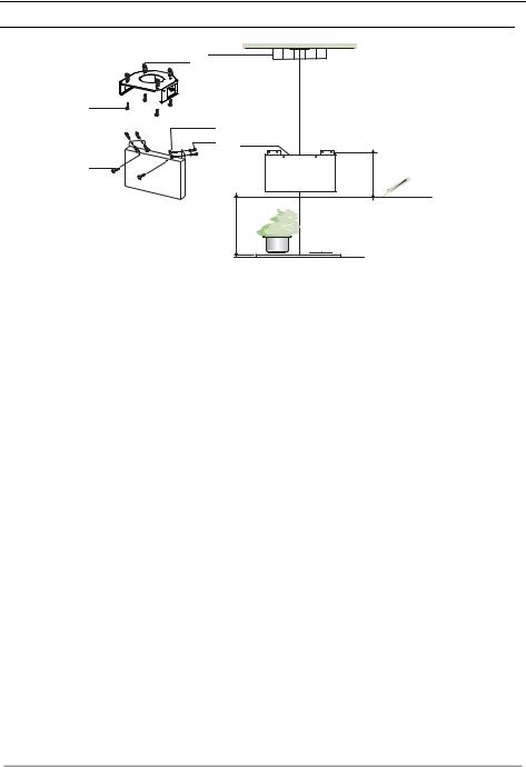
Drilling the wall and fixing the brackets
7.4
11
12a
12a
11 7.2
12b
650 min.
338,5
Do the following marking on the wall:
•a horizontal line at minimum 650 mm above the hob.
•As indicated, place the support fixing piece of the hood 7.2 at 338,5 mm above the horizontal reference line.
•Mark the centres of holes in the support.
•Drill ø 8 mm.
•Insert the dowels 11 into the holes.
•Fix the support using the screws 12a (4,2 x 44,4) supplied.
•Insert and screw two screws 12b (4,2 x 12,7) (supplied) into the holes for the hood body fixing, placed in the frontal part of the support fixing piece leaving a 5-6 mm distance between the support and the screw head.
•As indicated, place the upper chimney support 7.4 at the corner of the ceiling.
•Mark the centres of holes in the upper chimney support 7.4.
•Drill ø 8 mm.
•Insert the dowels 11 into the holes.
•Fix the upper chimney support using the screws 12a (4,2 x 44,4) supplied.
N.B. In case of impossibility to install the Upper chimney support 7.4. to the ceiling, it’s possible to do that lower, using the 4 Back holes instead of the Uppers.
To install the hood in recycling version it is necessary to follow the instructions described in the part concerning Recirculation version Air Outlet.
EN |
|
7 |
|
7 |

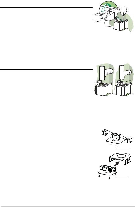
Mounting the hood body |
Vr |
• If, according to installer, the empty space between the lower part of the |
|
hood and the wall corner has to be filled, it is then necessary to install the |
|
corner spacer 7.1 at the hood basis using two screws 12c (2,9 x 9,5) sup- |
|
plied. |
12b |
• Fasten the two screws Vr placed at the hook areas of the hood. |
|
• Hang the hood body on the specific screws 12b (4,2 x 12,7). |
|
•Fasten definitively the support screws 12b (4,2 x 12,7).
•It is possible to level the hood body by adjusting the screws Vr.
•To definitively fix the hood to the ceiling it is necessary to use two remaining screws together with plug and washer. These have to be placed from inside the hood.
Connections
DUCTED VERSION AIR EXHAUST SYSTEM |
|
|
When installing the ducted version, connect the hood to the chimney using |
ø 150 |
ø 120 |
either a flexible or rigid pipe ø 150 or 120 mm, the choice of which is left to |
|
9 |
|
|
|
the installer. |
|
|
• To install a ø 120 mm air exhaust connection, insert the reducer flange 9 |
|
|
on the hood body outlet. |
|
|
•Fix the pipe in position using sufficient pipe clamps (not supplied).
•Remove any activated charcoal filters.
RECIRCULATION VERSION AIR OUTLET
•Insert the extension pieces 14.1 laterally on the air outlet connection piece
15.
Fix the connection piece with the extension pieces onto the support 7.3 using the two screws 12c (2,9 x 9,5) provided.
•Insert the assembled unit inside the upper chimney support 7.4 using the 4 screws 12c (2,9 x 9,5) provided.
•Connect the hood with the air outlet connection piece using a rigid or a flexible ø150 tube chosen by the installer. It will be necessary to use narrow strips (not provided) for this connection.
•Make sure that the charcoal filter has been mounted inside the hood.
12c |
12c |
EN |
|
8 |
|
8 |

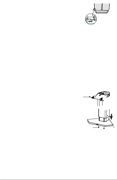
ELECTRICAL CONNECTION
• Connect the hood to the mains through a two-pole switch having a contact gap of at least 3 mm.
• Remove the grease filters (see paragraph Maintenance) being sure that the connector of the feeding cable is correctly inserted in the socket placed on the side of the fan.
|
Chimney mounting |
|
|
|
|
|
• |
Remove the chimney parts out of the packing leaving them one |
|
|
|
|
|
|
inside the other. |
12c |
||||
• |
Extend slightly the two side parts of the chimney and place the |
|
|
|
|
|
|
|
|
|
|
||
|
upper chimney on the chimney support 7.4. |
|
|
|
|
|
• |
Fix the upper chimney with two screws 12c (2,9 x 9,5) sup- |
|
|
|
|
|
|
|
|
|
|
||
|
|
|
|
|
||
|
plied |
|
|
|
|
|
• |
Move the lower chimney downwards until the two side lips of |
|
|
|
|
|
|
the chimney are completely inside their seats in the hood body. |
|
|
|
|
|
• Remove the grease filters. |
|
|
|
|
|
|
|
|
|
|
|
||
|
|
|
|
|
||
• |
Fix the chimney onto the hood body with two screws 12c (2,9 |
|
|
|
|
|
|
|
|
|
|
||
|
|
|
|
|
||
|
x 9,5) supplied, tighting them from inside the hood. |
|
|
|
|
12c |
• Replace the grease filters.
EN |
|
9 |
|
9 |

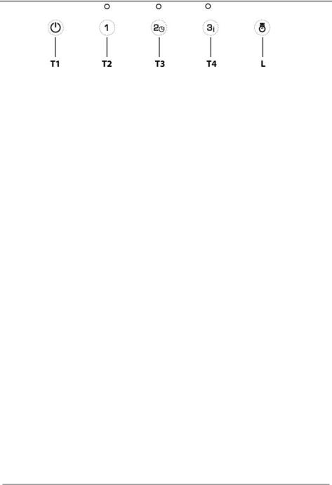
USE
|
|
|
Control panel |
|
|
Button |
Led |
Function |
|
|
T1 |
- |
Turns the Motor off. |
|
|
T2 |
Fixed |
Turns the Motor on at Speed one. |
|
|
T3 |
Fixed |
Turns the Motor on at Speed two. |
|
|
|
The Led |
Turns the Delay Function on and off when pressed and held for 2 seconds. |
|
|
|
corresponding |
|
|
|
|
to the speed |
Activates automatic switch-off (Motor+Lights) with a 30’ delay. Suitable |
|
|
|
that has been |
to complete elimination of residual odours. Can be activated from any |
|
|
|
set flashes |
position when the Intensive function is disabled, and is deactivated by |
|
|
|
once every |
pressing the button or turning the motor off. |
|
|
|
second. |
|
|
|
T4 |
Fixed |
Turns the Motor on at Speed Three. |
|
|
|
Flashes twice |
Turns the Intensive function on and off. |
|
|
|
a second. |
This speed is timed to run for 10 minutes. At the end of this time, the |
|
|
|
|
system returns automatically to the speed that was set before. It is disabled |
|
|
|
|
by pressing the button or turning the motor off. It cannot be activated when |
|
|
|
|
the Delay function is active. |
|
|
L |
- |
Turns the Lighting System on and off at maximum intensity. |
|
|
|
- |
Press and hold for 2 seconds to turn the Lighting System on and off at |
|
|
|
|
reduced intensity. |
|
EN |
|
1 |
|
10 |
MAINTENANCE
Grease filters
CLEANINGMETALSELF-SUPPORTINGGREASEFILTERS
•The filters must be cleaned every 2 months of operation, or more frequently for particularly heavy usage, and can be washed in a dishwasher.
•Remove the filters one at a time holding them up with one hand and pulling the handle downwards with theother hand at the same time.
•Wash the filters, taking care not to bend them. Allow them to dry before refitting.
•When refitting the filters, make sure that the handle is visible on the outside.
Activated charcoal filter (Recirculation version)
REPLACINGTHEACTIVATEDCHARCOALFILTER
•The filter is not washable and cannot be regenerated, and must be replaced approximately every 4 months of operation, or more frequently for particularly heavy usage.
•Remove the metal grease filters.
•Remove the saturated activated carbonfilter by releasing the fixing hooks.
•Fit the newfilter by hooking it into its seating.
•Refit the metal grease filters.
Lighting
LIGHTREPLACEMENT
20Whalogenlight.
•Remove the snap-on lamp cover by levering it from under the metal ring, supporting it with one hand.
•Remove the halogen lamp from the lamp holder by pulling gently.
•Replace the lamp with a new one of the same type, making sure that you insert the two pinsproperly intothe housings on the lamp holder.
•Replace the snap-on lamp cover.
EN
1
11
CONSIGLI E SUGGERIMENTI
Questo libretto di istruzioni per l'uso è previsto per più versioni dell' apparecchio. É possibile che siano descritti singoli particolari della dotazione, che non riguardano il Vostro apparecchio.
INSTALLAZIONE
•Il produttore declina qualsiasi responsabilità per danni dovuti ad installazione non corretta o non conforme alle regole dell’arte.
•La distanza minima di sicurezza tra il Piano di cottura e la Cappa deve essere di 650 mm, (alcuni modelli possono essere installati ad un’altezza inferiore, fare riferimento ai paragrafi ingombro e installazione).
•Verificare che la tensione di rete corrisponda a quella riportata nella targhetta posta all’interno della Cappa.
•Per Apparecchi in Classe Ia accertarsi che l’impianto elettrico domestico garantisca un corretto scarico a terra.
•Collegare la Cappa all’uscita dell’aria aspirata con tubazione di diametro pari o superiore a 120 mm. Il percorso della tubazione deve essere il più breve possibile.
•Non collegare la Cappa a condotti di scarico dei fumi prodotti da combustione (caldaie, caminetti, ecc.).
•Nel caso in cui nella stanza vengano utilizzati sia la Cappa che apparecchi non azionati da energia elettrica (ad esempio apparecchi utilizzatori di gas), si deve provvedere ad una aerazione sufficiente dell’ambiente. Se la cucina ne fosse sprovvista, praticare un’apertura che comunichi con l’esterno, per garantire il richiamo d’aria pulita. Un uso proprio e senza rischi si ottiene quando la depressione massima del locale non supera i 0,04 mBar.
•In caso di danneggiamento del cavo alimentazione, esso deve essere sostituito dal costruttore o dal servizio di assistenza tecnica, in modo da prevenire ogni rischio.
•Se le istruzioni di installazione del dispositivo di cottura a gas indicano che è necessaria una distanza maggiore di quella indicato sopra, è necessario tenerne conto. Bisogna rispettare tutte le normative relative allo scarico dell’aria.
USO
•La Cappa è stata progettata esclusivamente per uso domestico, per abbattere gli odori della cucina.
•Non fare mai uso improprio della Cappa.
•Non lasciare fiamme libere a forte intensità sotto la Cappa in funzione.
•Regolare sempre le fiamme in modo da evitare una evidente fuoriuscita laterale delle stesse rispetto al fondo delle pentole.
•Controllare le friggitrici durante l’uso: l’olio surriscaldato potrebbe infiammarsi.
•Non preparare alimenti flambè sotto la cappa da cucina; pericolo d'incendio.
•Questo apparecchio non deve essere utilizzato da persone (bambini inclusi) con ridotte capacità psichiche, sensoriali o mentali, oppure da persone senza esperienza e conoscenza, a meno che non siano controllati o istruiti all’uso dell’apparecchio da persone responsabili della loro sicurezza.
•I bambini devono essere supervisionati per assicurarsi che non giochino con l’apparecchio.
•“ATTENZIONE: Le parti accessibili possono diventare molto calde se utilizzate con degli apparecchi di cottura”.
MANUTENZIONE
•Prima di procedere a qualsiasi operazione di manutenzione, disinserire la Cappa togliendo la spina elettrica o spegnendo l’interruttore generale.
•Effettuare una scrupolosa e tempestiva manutenzione dei Filtri secondo gli intervalli consigliati (Rischio di incendio).
•Per la pulizia delle superfici della Cappa è sufficiente utilizzare un panno umido e detersivo liquido neutro.
Il simbolo  sul prodotto o sulla confezione indica che il prodotto non deve essere considerato come un normale rifiuto domestico, ma deve essere portato nel punto di raccolta appropriato per il riciclaggio di apparecchiature elettriche ed elettroniche. Provvedendo a smaltire questo prodotto in modo appropriato, si contribuisce a evitare potenziali conseguenze negative per l’ambiente e per la salute, che potrebbero derivare da uno smaltimento inadeguato del prodotto. Per informazioni più dettagliate sul riciclaggio di questo prodotto, contattare l’ufficio comunale, il servizio locale di smaltimento rifiuti oil negozioin cui è stato acquistatoil prodotto.
IT
2°
1
12
CARATTERISTICHE
Componenti
Rif. Q.tà Componenti di Prodotto
11 Corpo Cappa completo di: Comandi, Luce, Gruppo Ventilatore, Filtri
2 |
1 |
Camino Telescopico formato da: |
2.1 |
1 |
Camino Superiore |
2.2 |
1 |
Camino Inferiore |
9 |
1 |
Flangia di Riduzione ø 150-120 mm |
14.1 |
2 |
Prolunga Raccordo Uscita Aria |
15 |
1 |
Raccordo Uscita Aria |
Rif. |
Q.tà |
Componenti di Installazione |
7.1 |
1 |
Tappo ad Angolo Inferiore |
7.2 |
1 |
Supporto Attacco Cappa |
7.3 |
1 |
Supporto Raccordo Uscita Aria |
7.4 |
1 |
Supporto Camino Superiore |
11 |
10 |
Tasselli ø 8 |
12a |
10 |
Viti 4,2 x 44,4 |
12b |
2 |
Viti 4,2 x 12,7 |
12c |
12 |
Viti 2,9 x 9,5 |
|
Q.tà |
Documentazione |
|
1 |
Libretto Istruzioni |
12c |
11 |
|
7.4 |
|
12a |
|
15 |
|
14.1 |
2.1 |
|
2 |
7.3 |
2.2 |
12c |
|
9 |
|
11 |
|
12a |
12c |
|
|
7.2 |
|
12b |
11 |
12c |
|
|
1 |
7.1 |
|
|
|
12a |
IT |
|
1 |
|
13 |

Ingombro
IT |
|
1 |
|
14 |
INSTALLAZIONE
Foratura Parete e Fissaggio Staffe
7.4
11
12a
12a
11 7.2
12b
650 min.
338,5
Tracciare sulla Parete:
•una linea Orizzontale a: 650 mm min. sopra il Piano di Cottura.
•Appoggiare come indicato il Supporto Attacco Cappa 7.2 a 338,5 mm sopra la linea Orizzontale di riferimento.
•Segnare i centri dei Fori del Supporto.
•Forare ø 8 mm i punti segnati.
•Inserire i tasselli 11 nei fori.
•Fissare il Supporto, utilizzando le Viti 12a (4,2 x 44,4) in dotazione.
•Avvitare 2 Viti 12b (4,2 x 12,7) in dotazione nei fori per il fissaggio del Corpo Cappa, posizionati sulla piastra frontale del Supporto Attacco Cappa, lasciando uno spazio di 5-6 mm fra il supporto e la testa della vite.
•Appoggiare come indicato il Supporto Camino Superiore 7.4 sull’angolo del soffitto.
•Segnare i centri dei Fori del Supporto Camino Superiore 7.4.
•Forare ø 8 mm i punti segnati.
•Inserire i tasselli 11 nei fori.
•Fissare il Supporto Camino Superiore utilizzando le Viti 12a (4,2 x 44,4) in dotazione.
N.B. Qualora non fosse possibile installare il Supporto Camino Superiore 7.4 al soffitto, è possibile farlo più in basso, utilizzando i 4 Fori Posteriori al posto di quelli Superiori.
Per installazione in Versione Filtrante, effettuare subito le operazioni descritte nel paragrafo Uscita Aria Versione Filtrante.
IT |
|
1 |
|
15 |
Montaggio Corpo Cappa
Vr
• Qualora l’installatore ritenga opportuno chiudere lo spazio vuoto che rimane nella parte inferiore tra la Cappa e l’angolo del muro, si deve installare il Tappo ad Angolo 7.1 alla base della Cappa con 2 Viti 12c (2,9
x 9,5)in dotazione. |
12b |
• Serrare le 2 Viti Vr situate sui punti di aggancio del Corpo Cappa.
• Agganciare il Corpo Cappa alle Viti 12b (4,2 x 12,7) predisposte.
•Serrare definitivamente le Viti 12b (4,2 x 12,7) di supporto.
•Agire sulle Viti Vr per livellare il Corpo Cappa.
•Assicurare la cappa al muro per mezzo di altre due viti con tassello e rondella, posizionabili dall’interno del corpo cappa.
Connessioni
USCITA ARIA VERSIONE ASPIRANTE
Per installazione in Versione Aspirante collegare la Cappa alla tubazione di |
ø 150 |
ø 120 |
uscita per mezzo di un tubo rigido o flessibile di ø150 o 120 mm, la cui scel- |
|
9 |
ta è lasciata all'installatore. |
|
|
• Per collegamento con tubo ø120 mm, inserire la Flangia di riduzione 9 |
|
|
sull’Uscita del Corpo Cappa. |
|
|
• Fissare il tubo con adeguate fascette stringitubo. Il materiale occorrente |
|
|
non è in dotazione. |
|
|
• Togliere eventuali Filtri Antiodore al Carbone attivo. |
|
|
USCITA ARIA VERSIONE FILTRANTE
•Inserire lateralmente le Prolunghe Raccordo 14.1 sul Raccordo 15.
•Avvitare il Raccordo con Prolunghe al Supporto 7.3 con 2 Viti 12c (2,9 x 9,5) in dotazione.
•Infilare il Supporto così ottenuto al Supporto Camino Superiore 7.4 e fissarlo con 4 Viti 12c (2,9 x 9,5) in dotazione.
•Collegare e fissare con due Fascette, non in dotazione, la Cappa al Raccordo uscita Aria con un tubo rigido o flessibile di ø150, la cui scelta è lasciata all'installatore.
•Assicurarsi della presenza del Filtro Antiodore al Carbone attivo.
12c |
12c |
IT |
|
1 |
|
16 |
CONNESSIONE ELETTRICA
• Collegare la Cappa all’Alimentazione di Rete interponendo un Interruttore bipolare con apertura dei contatti di almeno 3 mm.
• Rimuovere i Filtri antigrasso (vedi par. “Manutenzione”) e assicurarsi che il connettore del Cavo di alimentazione sia correttamente inserito nella presa dell’Aspiratore
|
Montaggio Camino |
|
|
|
|
|
• Prendere i Camini dalla scatola lasciandoli l’uno dentro l’altro. |
|
|
|
|
|
|
• |
Allargare leggermente le due falde laterali e appoggiare o inse- |
12c |
||||
|
rire i Camini da sopra sul Supporto Camino 7.4. |
|
|
|
|
|
|
|
|
|
|
|
|
• |
Fissare il Camino Superiore con 2 Viti 12c (2,9 x 9,5) in dota- |
|
|
|
|
|
|
zione. |
|
|
|
|
|
|
|
|
|
|
|
|
|
|
|
|
|
|
|
• |
Far scorrere il Camino inferiore verso il basso finche le due |
|
|
|
|
|
|
Linguette laterali non sono completamente inserite nelle appo- |
|
|
|
|
|
|
site asole sul Corpo Cappa. |
|
|
|
|
|
• Togliere i Filtri antigrasso. |
|
|
|
|
|
|
|
|
|
|
|
||
• |
Fissare il Camino al Corpo Cappa dall’interno, con 2 Viti 12c |
|
|
|
|
|
|
|
|
|
|
||
|
|
|
|
|
||
|
(2,9 x 9,5) in dotazione. |
|
|
|
|
12c |
• Rimontare i Filtri antigrasso. |
|
|
|
|
|
|
IT |
|
1 |
|
17 |
USO
|
|
|
Quadro comandi |
|
|
Tasto |
Led |
Funzione |
|
|
T1 |
- |
Spegne il Motore. |
|
|
T2 |
Fisso |
Accende il Motore alla Prima velocità. |
|
|
T3 |
Fisso |
Accende il Motore alla Seconda velocità. |
|
|
|
Lampeggia una |
Tenendo premuto per 2 secondi accende e spegne la Funzione Delay. |
|
|
|
volta al secondo il |
Attiva lo spegnimento automatico(Motore+Luci) ritardato di 30’. Adatto |
|
|
|
corrispondente |
per completare l’eliminazione di odori residui. Attivabile da qualsiasi posi- |
|
|
|
Led della Velocità |
zione con funzione Intensiva disabilitata, si disattiva premendo il tasto o |
|
|
|
impostata. |
spegnendo il motore. |
|
|
T4 |
Fisso |
Accende il Motore alla Terza velocità. |
|
|
|
Lampeggia due |
Accende e spegne la funzione Intensiva. |
|
|
|
volta al secondo |
Questa velocità è temporizzata a 10 minuti. Terminato il tempo, il sistema |
|
|
|
|
ritorna automaticamente alla velocità precedentemente selezionata. Si |
|
|
|
|
disattiva premendo il tasto o spegnendo il motore. Non è attivabile con fun- |
|
|
|
|
zione Delay attiva. |
|
|
L |
- |
Accende e spegne l’Impianto di Illuminazione alla massima intensità |
|
|
|
- |
Tenendo premuto per 2 secondi accende e spegne l’Impianto di Illumina- |
|
|
|
|
zione ad intensità ridotta. |
|
IT |
|
1 |
|
18 |
 Loading...