


IT
GB
FR
DE
TR
PL
CZ
Istruzioni per l’uso e l’installazione
Cappa
Instructions for use and installation Mode d’emploi et installation
Bedienungsanleitung und Einrichtung
Dunstabzugshaube
Kullanım ve montaj talimatları
Davlumbaz
Instrukcja obsługi i instalacji
Okap kuchenny
Uživatelská Pøíruèka
Odsavač par
FDL 664
FDL 764
FDL 964
FDL 6064 FDL 6064/1
FDL 9064 FDL 9064/1
Downloaded from www.Manualslib.com manuals search engine

INDICE
IT
AVVERTENZE - COMPONENTI ........................................................................................................................................... |
3 |
INSTALLAZIONE ................................................................................................................................................................... |
4 |
USO - MANUTENZIONE ....................................................................................................................................................... |
5 |
INDEX
EN
WARNINGS - COMPONENTS .............................................................................................................................................. |
6 |
INSTALLATION...................................................................................................................................................................... |
7 |
USE - MAINTENANCE .......................................................................................................................................................... |
8 |
SOMMAIRE
FR
ATTENTION - COMPOSANTS |
.............................................................................................................................................. 9 |
INSTALLATION.................................................................................................................................................................... |
10 |
UTILISATION - ENTRETIEN ............................................................................................................................................... |
11 |
INHALTSVERZEICHNIS
DE
HINWEIS - KOMPONENTEN .............................................................................................................................................. |
12 |
MONTAGE ........................................................................................................................................................................... |
13 |
BEDIENUNG - WARTUNG................................................................................................................................................. |
14 |
IÇERIKLER |
TR |
UYARILAR - PARÇALARI.................................................................................................................................................... |
15 |
MONTAJ............................................................................................................................................................................... |
16 |
KULLANIM - BAKIMI VE TEMİZLENMESİ.......................................................................................................................... |
17 |
SPIS TREŚCI
PL
OSTRZEŻENIA - CZĘŚCI SKŁADOWE.............................................................................................................................. |
18 |
INSTALACJA........................................................................................................................................................................ |
19 |
UŻYTKOWANIE – KONSERWACJA................................................................................................................................... |
22 |
OBSAH
CZ
UPOZORNĚNÍ - DÍLY .......................................................................................................................................................... |
23 |
INSTALACE ......................................................................................................................................................................... |
24 |
POUŽITÍ - ÚDRŽBA ............................................................................................................................................................. |
25 |
2
Downloaded from www.Manualslib.com manuals search engine
AVVERTENZE - COMPONENTI
AVVERTENZE
-La distanza minima tra il piano di cottura e la parte inferiore della cappa deve essere almeno di 650mm.
-Osservare le seguenti istruzioni riguardanti il funzionamento della cappa quando l'aria viene convogliata verso l'esterno. (utilizzo aspirante)
-Deve essere prevista un'adeguata areazione del locale quando la cappa o apparecchi alimentati con energia diversa da quella elettrica vengono usati contemporaneamente; la pressione negativa della stanza non deve superare 4 Pa (4x10⁻⁵ bar).
-L'aria raccolta non deve essere convogliata in un condotto usato per lo scarico dei fumi di apparecchi alimentati con energia diversa da quella elettrica.
-Rispettare le prescrizioni delle Autorità competenti relative allo scarico dell'aria da evacuare.
-Evitare la presenza di fiamma libera nello spazio sottostante la cappa.
-La cappa è stata costruita con isolamento in Classe II pertanto non necessita di connessione a terra.
-Prima di effettuare tutte le operazioni di manutenzione scollegare l'apparecchio dall'alimentazione elettrica.
-Questo apparecchio non deve essere utilizzato da persone (bambini inclusi) con ridotte capacità psichiche, sensoriali o mentali, oppure da persone senza esperienza e conoscenza, a meno che non siano controllati o istruiti all’uso dell’apparecchio da persone responsabili della loro sicurezza.
-I bambini devono essere supervisionati per assicurarsi che non giochino con l’apparecchio.
ALLACCIAMENTO DEL CAVO DI ALIMENTAZIONE ALLA RETE
Prima dell'installazione verificare che la tensione della rete indicata sull'apposita targhetta applicata all'interno dell'apparecchio, corrisponda alla tensione della vostra abitazione. Nel caso in cui la Cappa non fosse provvista di spina, montare sul cavo alimentazione una spina normalizzata per il carico indicato sulla targhetta caratteristiche; nel caso di collegamento elettrico diretto alla rete è necessario interporre tra l'apparecchio e la rete un interruttore omnipolare con apertura minima tra i contatti di 3mm, dimensionato al carico e rispondente alle norme in vigore.
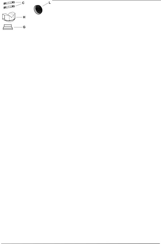
COMPONENTI
-2 staffe di fissaggio C
-1 flangia di riduzione G
-1 raccordo filtrante H
-2 filtri al carbone attivo L (facoltativo)
Il simbolo  sul prodotto o sulla confezione indica che il prodotto non deve essere considerato come un normale rifiuto domestico, ma deve essere portato nel punto di raccolta appropriato per il riciclaggio di apparecchiature elettriche ed elettroniche. Provvedendo a smaltire questo prodotto in modo appropriato, si contribuisce a evitare potenziali conseguenze negative per l’ambiente e per la salute, che potrebbero derivare da uno smaltimento inadeguato del prodotto. Per informazioni più dettagliate sul riciclaggio di questo prodotto, contattare l’ufficio comunale, il servizio locale di smaltimento rifiuti o il negozio in cui è stato acquistato il prodotto.
IT |
|
3 |
|
3 |
Downloaded from www.Manualslib.com manuals search engine

INSTALLAZIONE
La cappa deve essere montata al centro del piano cottura. La distanza minima tra il piano di cottura e la superficie inferiore della cappa deve essere di 650mm.
Per il montaggio della cappa procedere nel modo seguente:
1)Praticare n°6 fori (X1-X2-J) Ø 8mm rispettando le quote indicate in fig. 1.
2)Per i vari montaggi utilizzare le viti e i tasselli espansione in dotazione.
3)Bloccare le staffe C (fig. 2) alla parete nei fori X1-X2.
4)Fissare la cappa alla parete nei fori esterni J1 e J2 (fig. 3).
5)Montaggio ASPIRANTE o FILTRANTE:
• ASPIRANTE
Per installazione in Versione Aspirante collegare la Cappa alla tubazione di uscita per mezzo di un tubo rigido o flessibile di ø150 o 120 mm, la cui scelta è lasciata all'installatore.
•Per collegamento con tubo ø120 mm, inserire la Flangia di riduzione 9 sull’Uscita del Corpo Cappa.
•Fissare il tubo con adeguate fascette stringitubo. Il materiale occorrente non è in dotazione.
•Togliere eventuali Filtri Antiodore al Carbone attivo.
•FILTRANTE (VERSIONE OPZIONALE)
-Inserire il Raccordo filtrante H (fig. 6).
-Montare i filtri carbone attivo L (fig. 7) bloccarli ruotando in senso orario (circa 10°) fino allo scatto di arresto. Per lo smontaggio eseguire le operazioni all'inverso.
Montaggio Camini
6)Fissare il camino superiore A (fig. 8) alle staffe C (fig. 2/ fig. 8) utilizzando n°4 viti autofilettanti Ø2,9mm in dotazione. La distanza tra i fori di fissaggio X1 e X2 viene stabilita dal- l'altezza del camino superiore H .
7)Applicare frontalmente il camino inferiore B (fig. 9) allargando leggermente le due parti laterali e poi inserirlo nella cappa (fig. 9).
IT |
|
4 |
|
4 |
Downloaded from www.Manualslib.com manuals search engine

USO - MANUTENZIONE
USO
Vi raccomandiamo di far funzionare l'apparecchio poco prima di procedere alla cottura di qualsiasi vivanda e di lasciar funzionare lo stesso ancora per 15 minuti dopo la cottura, comunque fin tanto che ogni odore sia scomparso.
1)Quadro comandi con interruttori
-Un interruttore che comanda l'accensione dell'impianto di illuminazione.
-Un interruttore per commutare le tre velocità d'esercizio.
-Una generica spia di segnalazione motore in funzione.
2)Quadro comandi con pulsanti
-Un pulsante che comanda l'accensione del motore in prima velocità, adatta ad un ricambio d'aria continuo particolarmente silenzioso, in presenza di pochi vapori di cottura.
-Un pulsante che comanda il motore in seconda velocità, adatta alla maggior parte delle condizioni di uso, dato l'ottimo rapporto tra portata d'aria trattata e livello di rumorosità.
-Un pulsante che comanda il motore in terza velocità, adatta a fronteggiare le massime e- missioni di vapori di cottura, anche per tempi prolungati.
-Un pulsante che comanda l'accensione dell'impianto di illuminazione.
MANUTENZIONE
N.B. Prima di qualsiasi intervento di manutenzione, riparazione ed eventuale sostituzione lampade, disinserire l'apparecchio dalla rete elettrica.
1. Illuminazione
E' costituita da due lampade da 40 W. Per effettuare una sostituzione operare come segue (fig.10):
Togliere uno dei perni ai lati della plafoniera. Far scorrere il vetro verso il lato senza perno fino a liberare la punta opposta, quindi tirare leggermente verso il basso.Sostituire le lampade e rimontare il vetro con sequenza opposta.
2. Filtri
Ad intervalli più o meno frequenti, secondo l'uso della cappa, comunque una volta ogni 2 mesi, i filtri metallici debbono essere smontati e lavati con acqua calda saponosa, o direttamente lavati in lavastoviglie e rimontati asciugati (i filtri in carbone attivo non devono essere assolutamente lavati e devono essere sostituiti ogni 2 mesi).
3. Pulizia
Per la pulizia esterna della cappa utilizzare un panno umido con alcool o con prodotti adatti reperibili in commercio. Evitate di usare degli elementi abrasivi.
IMPORTANTE: L'impiego di fiamma libera è dannoso ai filtri, pertanto è sconsigliato di lasciare acceso un bruciatore a gas senza pentola. È obbligatorio mettere in atto le operazioni di pulizia della cappa o dei filtri, non che la loro periodica sostituzione secondo le nostre istruzioni per evitare pericoli di incendio.
ATTENZIONE: La casa produttrice non risponde degli eventuali danni causati dalla mancata manutenzione del filtro antigrasso (lavaggio ogni due mesi), sostituzione del filtro carbone ed il non rispetto delle istruzioni di montaggio ed allacciamento elettrico sopra descritte.
IT |
|
5 |
|
5 |
Downloaded from www.Manualslib.com manuals search engine

WARNINGS - COMPONENTS
WARNINGS
This appliance has been designed for use as either an EXTRACTION (ducting to the outside) or RECIRCULATION (filtering) hood. The measurements contained on the drawings in this booklet refer to two models of cooker hood. Therefore, it is essential that you refer to the correct drawing when taking measurements for installation.
-The minimum distance between the cooking surface and the metal grease filters on the underside of the hood must be 650mm.
-This cooker hood must be installed in accordance with the installation instructions and all requirements must be adhered to.
-If the room where the cooker hood is to be used contains a fuel burning appliance such as a central heating boiler then its flue must be of the room sealed or balance flue type.
-If other types of flue or appliances are fitted ensure that there is an adequate supply of air to the room.
-When the range hood and appliance supplied with energy other than electricity are simultaneously in operation, the negative pressure in the room must not exceed 4 Pa (4x10⁻⁵ bar).
-The ducting system for this appliance must not be connected to any ventilation system which is being used for any other purpose.
-The ducting system for this appliance must not be connected to any existing ventilation system which is being used for any other purpose.
-Do not leave naked flames or carry out flambè cooking under this cooker hood.
-This appliance is not intended for use by persons (including children) with reduced physical, sensory or mental capabilities, or lack of experience and knowledge, unless they have been given supervision or instruction concerning use of the appliance by a person responsible for their safety.
-Children should be supervised to ensure that they do not play with the appliance.
CONNECTING THE POWER CABLE TO THE MAINS POWER SUPPLY
Before installation, check that the mains voltage indicated on the rating plate inside the appliance corresponds to the voltage available in your home. If the Hood is not fitted with a plug, fit the power cable with a plug of a type approved for the load indicated on the rating plate; when connecting directly to the mains, insert an omnipolar circuit breaker with a minimum contact aperture of 3mm and a size suitable for the load in question between the appliance and the mains supply, making sure it is of a type that complies with current regulations.
COMPONENTS
-2 No Wall Brackets C
-1 No 150-120mm Ducting Spigot G
-1 No Air Outlet Connection H
-2 No Charcoal Filters L (Optional)
The symbol  on the product or on its packaging indicates that this product may not be treated as household waste. Instead it shall be handed over to the applicable collection point for the recycling of electrical and electronic equipment. By ensuring this product is disposed of correctly, you will help prevent potential negative consequences for the environment and human health, which could otherwise be caused by inappropriate waste handling of this product. For more detailed information about recycling of this product, please contact your local city office, your household waste disposal service or the shop where you purchased the product.
EN |
|
6 |
|
6 |
Downloaded from www.Manualslib.com manuals search engine

INSTALLATION
The cooker hood must be installed centrally over a cooking appliance. The minimum distance between the cooking surface and the metal grease filters on the underside of the hood must be at least 650mm.
To install the hood proceed as follows:
1)Drill six 8mm diameter holes at X1-X2-J and insert the plastic rawl plugs supplied as illustrated in fig. 2 ensuring the brackets are fitted as shown in the blow up.
2)Secure the two brackets C to the wall inserting two of the screws supplied through the two holes on line X1-X2 as illustrated in fig. 2.
3)Slide the canopy down the wall to locate the key hole over the washer then secure the canopy to the wall by inserting two of the screws supplied through the two outer holes in the rim of the canopy J1 and J2 as illustrated in fig. 3.
4)EXTRACTION OR RECIRCULATION INSTALLATION:
• EXTRACTION (DUCTED)
When installing the ducted version, connect the hood to the chimney using either a flexible or rigid pipe ø 150 or 120 mm, the choice of which is left to the installer.
•To install a ø 120 mm air exhaust connection, insert the reducer flange 9 on the hood body outlet.
•Fix the pipe in position using sufficient pipe clamps (not supplied).
•Remove any activated charcoal filters.
•RECIRCULATION (FILTERED)
•When the hood is fitted in the recirculation mode the Air Outlet Connection H should be fitted as illustrated in fig. 6.
•Fit the (optional) charcoal filters by repeating the following operation on each side of the motor housing. Place the two key hole slots in the filter L and turn the filter clockwise to lock the filter in position as illustrated in fig. 7.
WARNING: It is a possible fire hazard if the metal grease filters are not cleaned and the charcoal filters replaced regularly.
Fitting The Chimney
5)FITTING THE CHIMNEY UPPER
To fit the upper chimney A, place the top edge of the chimney over the bracket C as illustrated in fig. 8 and secure the chimney using two of the 2.9mm self tapping screws provided.
The distance H in the height between the fixing holes X1 and X2 is determined by the height of the upper chimney A.
6)FITTING THE CHIMNEY LOWER
To fit the lower chimney B, apply slight force to the two rear edges to increase the width of the apperture, then sleeve the chimney B over the chimney A as illustrated in fig. 9.
EN |
|
7 |
|
7 |
Downloaded from www.Manualslib.com manuals search engine

USE - MAINTENANCE
USE
The cooker hood functions are controlled by a series of slider or push button switches mounted on the front of the hood and control the worktop lighting and fan motor speeds. This cooker hood will not remove steam.
1)SLIDER SWITCHES
-A switch controls the wotktop lighting - ON/OFF.
-A switch controls the fan speeds - OFF/ON-1-2-3.
-The red neon lamp illuminates when the motor is switched ON .
2)PUSH BUTTON SWITCHES
-A switch controls the worktop lighting - ON/OFF.
-A button switches the motor OFF/ON at the low speed setting.
-A button switches the motor to the medium speed setting.
-A button switches the motor to the high speed setting.
-The red neon lamp illuminates when the motor is switched ON.
3)SPEED SETTINGS
-1/Low should be selected when simmering or when using only one pan.
-2/Medium should be selected for cooking when using up to four pans.
-3/High should be selected when frying or cooking food with a strong odour.
MAINTENANCE
N.B. Before carring out any kind of maintenance, cleaning or replacing lamps, disconnect the hood from the mains supply.
1.Lighting
Comprises two 40W bulbs. To replace the bulbs, proceed as follows (fig.10): Remove one of the pins at the sides of the lamp cover. Slide the glass towards the side from which the pin has been removed until the opposite edge has been freed, then pull gently downwards. Replace the bults and fit the glass again by repeating the above operations in reverse order.
2.Filters
-The metal grease filter should be cleaned every two months or more frequently if the hood is used consistently and can be cleaned in a dishwasher or by hand using a mild detergent or liquid soap. When replacing, ensure that they are dry.
-The charcoal filter cannot be washed and should be replaced at least every 2 months or more frequently if the hood is used consistently.
3.Cleaning
When cleaning the hood, it is recommended to use a damp cloth and mild liquid household cleaner. Never use abrasive cleaning materials.
IMPORTANT: When using a gas hob in connection with the cooker hood never leave the burners of the hob uncovered while the hood is in use or when the pans have been removed. It is very important to follow all instructions for cleaning the hood and filters. There could be a possible fire hazard if the filters are not replaced according to these instructions.
ATTENTION: The manufacturer declines all responsibility for any damage or injury caused as a result of not following the instructions for installation, for maintenance and replacement times of filters indicated (in order to avoid a possible risk of fire when the filters are saturated with grease).
EN |
|
8 |
|
8 |
Downloaded from www.Manualslib.com manuals search engine

ATTENTION - COMPOSANTS
ATTENTION
Cet appareil a été conçu pour être employé en version ASPIRANTE (évacuation de l'air vers l'extérieur) ou en version RECYCLAGE (air conduite vers l'intérieur).
-La distance minimum entre le plan de cuisson et la partie inférieure de la hotte doit être au moins de 650mm.
-Il faut prévoir une aération convenable de la pièce lorsque la hotte et les appareils alimentés avec énergie différente de celle éléctrique sont utilisés en même temps; la pression négative de la pièce ne doit pas dépasser 4Pa (4x10⁻⁵ bar).
-L'air recueillie ne doit pas être dirigée dans un conduit utilisé pour la décharge des fumées des appareils alimentés avec énergie différente de celle éléctrique.
-Respecter les prescriptions des autorités compétentes relatives à la décharge de l'air à evacuer.
-Eviter la présence de flammes libres dans l'espace au dessous de la hotte.
-La hotte a été construite avec isolement en classe II, donc il n'y a pas besoin de la relier à la terre.
-Avant d'effectuer toutes les opérations d'entretien, débrancher l'appareil de l'alimentation éléctrique.
-Cet appareil ne doit pas être utilisé par des personnes (y compris les enfants) ayant des capacités psychiques, sensorielles ou mentales réduites, ni par des personnes n’ayant pas l’expérience et la connaissance de ce type d’appareils, à moins d'être sous le contrôle et la formation de personnes responsables de leur sécurité.
-Les enfants doivent être surveillés pour s'assurer qu'ils ne jouent pas avec l'appareil.
BRANCHEMENT DU CÂBLE ÉLECTRIQUE AU RÉSEAU
Avant l’installation, vérifier que la tension du réseau indiquée sur la plaquette se trouvant à l’intérieur de l’appareil correspond à la tension électrique de votre habitation. Si la hotte n’est pas munie de fiche électrique, monter une fiche à norme sur le câble d’alimentation qui soit adaptée à la tension indiquée sur la plaquette des caractéristiques. En cas de branchement électrique direct sur le réseau, il faudra placer un interrupteur omnipolaire entre l’appareil et le réseau ayant une ouverture minimum entre les contacts de 3 mm, et adapté à la tension et répondant aux normes en vigueur.
COMPOSANTS
-2 brides C
-1 bride de réduction G
-1 raccord filtrant H
-2 filtres charbon actif L (optionnel)
Le symbole  sur le produit ou son emballage indique que ce produit ne peut être traité comme déchet ménager. Il doit plutôt être remis au point de ramassage concerné, se chargeant du recyclage du matériel électrique et électronique. En vous assurant que ce produit est éliminé correctement, vous favorisez la prévention des conséquences négatives pour l’environnement et la santé humaine qui, sinon, seraient le résultat d’un traitement inapproprié des déchets de ce produit. Pour obtenir plus de détails sur le recyclage de ce produit, veuillez prendre contact avec le bureau municipal de votre région, votre service d’élimination des déchets ménagers ou le magasin où vous avez acheté le produit.
FR |
|
9 |
|
9 |
Downloaded from www.Manualslib.com manuals search engine
 Loading...