


|
|
|
|
|
|
|
|
Instructions for use and installation |
|
|
GB |
|
||
|
|
|
Cooker Hood |
|
|
|
|
||
|
|
Istruzioni per l’uso e l’installazione |
||
|
IT |
|
||
|
|
|
Cappa |
|
|
|
|
||
|
|
Mode d’emploi et installation |
||
|
FR |
|
||
|
|
|
Hotte de Cuisine |
|
|
|
|
||
|
|
Bedienungsanleitung und Einrichtung |
||
|
DE |
|
||
|
|
|
Dunstabzugshaube |
|
|
|
|
||
|
|
Kullanım ve montaj talimatları |
||
|
TR |
|
||
|
|
|
Davlumbaz |
|
|
|
|
||
FDB 6078
FDB 7078
FDB 8078
FDB 9078
FDB 12078

INDEX |
EN |
RECOMMENDATIONS AND SUGGESTIONS ..................................................................................................................... |
3 |
CHARACTERISTICS ............................................................................................................................................................. |
4 |
INSTALLATION...................................................................................................................................................................... |
5 |
USE ........................................................................................................................................................................................ |
8 |
MAINTENANCE ..................................................................................................................................................................... |
9 |
INDICE |
IT |
CONSIGLI E SUGGERIMENTI............................................................................................................................................ |
12 |
CARATTERISTICHE............................................................................................................................................................ |
13 |
INSTALLAZIONE ................................................................................................................................................................. |
14 |
USO...................................................................................................................................................................................... |
17 |
MANUTENZIONE ................................................................................................................................................................ |
18 |
SOMMAIRE |
FR |
CONSEILS ET SUGGESTIONS.......................................................................................................................................... |
21 |
CARACTERISTIQUES......................................................................................................................................................... |
22 |
INSTALLATION.................................................................................................................................................................... |
23 |
UTILISATION ....................................................................................................................................................................... |
26 |
ENTRETIEN ......................................................................................................................................................................... |
27 |
INHALTSVERZEICHNIS |
DE |
EMPFEHLUNGEN UND HINWEISE ................................................................................................................................... |
30 |
CHARAKTERISTIKEN ......................................................................................................................................................... |
31 |
MONTAGE ........................................................................................................................................................................... |
32 |
BEDIENUNG........................................................................................................................................................................ |
35 |
WARTUNG........................................................................................................................................................................... |
36 |
IÇERIKLER |
TR |
TAVSIYELER VE ÖNERILER.............................................................................................................................................. |
39 |
ÖZELLIKLER........................................................................................................................................................................ |
40 |
MONTAJ............................................................................................................................................................................... |
41 |
KULLANIM ........................................................................................................................................................................... |
44 |
BAKIM .................................................................................................................................................................................. |
45 |
2
RECOMMENDATIONS AND SUGGESTIONS
 The Instructions for Use apply to several versions of this appliance. Accordingly, you may find descriptions of individual features that do not apply to your specific appliance.
INSTALLATION
• The manufacturer will not be held liable for any damages resulting from incorrect or improper
installation.
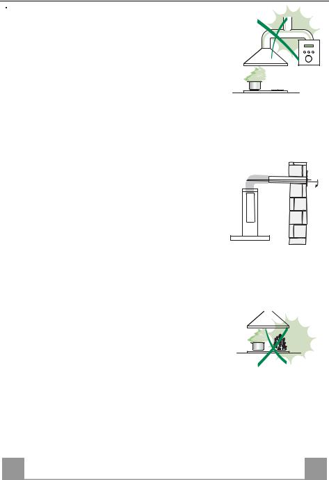
• The minimum safety distance between the cooker top and the extractor hood is 650 mm (some models can be installed at a lower height, please refer to the paragraphs on working dimensions and installation).
• Check that the mains voltage corresponds to that indicated on the rating plate fixed to the inside of the hood.
• For Class I appliances, check that the domestic power supply guarantees adequate earthing. Connect the extractor to the exhaust flue through a pipe of minimum diameter 120 mm. The route of the flue must be as short as possible.
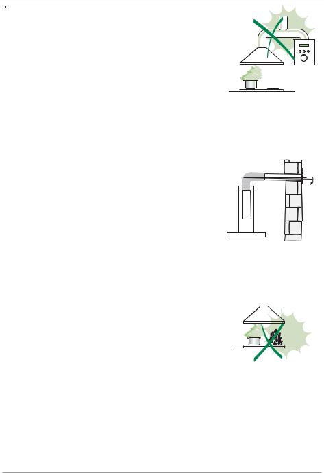
•Do not connect the extractor hood to exhaust ducts carrying combustion fumes (boilers, fireplaces, etc.).
•If the extractor is used in conjunction with non-electrical appliances (e.g. gas burning appliances), a sufficient degree of aeration must be guaranteed in the room in order to prevent the backflow of exhaust gas. The kitchen must have an opening communicating directly with the open air in order
to guarantee the entry of clean air. When the cooker hood is used in conjunction with appliances |
|
supplied with energy other than electric, the negative pressure in the room must not exceed 0,04 |
|
mbar to prevent fumes being drawn back into the room by the cooker hood. |
2° |
• In the event of damage to the power cable, it must be replaced by the manufacturer or by the |
|
technical service department, in order to prevent any risks. |
|
• If the instructions for installation for the gas hob specify a greater distance specified above, this has |
|
to be taken into account. Regulations concerning the discharge of air have to be fulfilled. |
|
USE
•The extractor hood has been designed exclusively for domestic use to eliminate kitchen smells.
•Never use the hood for purposes other than for which it has been designed.
• Never leave high naked flames under the hood when it is in operation.
•Adjust the flame intensity to direct it onto the bottom of the pan only, making sure that it does not engulf the sides.
•Deep fat fryers must be continuously monitored during use: overheated oil can burst into flames.
•Do not flambè under the range hood; risk of fire
•This appliance is not intended for use by persons (including children) with reduced physical, sensory or mental capabilities, or lack of experience and knowledge, unless they have been given supervision or instruction concerning use of the appliance by a person responsible for their safety.
•Children should be supervised to ensure that they do not play with the appliance.
•“ CAUTION: Accessible parts may become hot when used with cooking appliances.”.
MAINTENANCE
• Switch off or unplug the appliance from the mains supply before carrying out any maintenance work.
• Clean and/or replace the Filters after the specified time period (Fire hazard).
• Clean the hood using a damp cloth and a neutral liquid detergent.
The symbol  on the product or on its packaging indicates that this product may not be treated as household waste. Instead it shall be handed over to the applicablecollectionpointfortherecyclingofelectricalandelectronicequipment.Byensuringthisproductisdisposedofcorrectly,youwillhelppreventpotentialnegative consequencesfortheenvironmentandhumanhealth,whichcouldotherwisebecausedbyinappropriatewastehandlingofthisproduct.Formoredetailedinformation aboutrecyclingofthisproduct,pleasecontactyourlocalcityoffice,yourhouseholdwastedisposalserviceortheshopwhereyoupurchasedtheproduct.
EN |
|
3 |
|
3 |

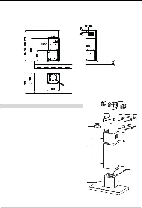
CHARACTERISTICS
Dimensions
|
|
Components |
|
15 |
|
|
|
|
|
|
14.1 |
||
Ref. |
Q.ty |
Product Components |
|
|
||
|
|
|
|
|||
1 |
1 |
Hood Body, complete with: Controls, Light, Blower, |
7.3 |
12a |
7.2.1 |
11 |
2 |
|
Filters |
|
|||
1 |
Telescopic Chimney comprising: |
|
|
|
|
|
2.1 |
1 |
Upper Section |
9 |
|
|
|
2.2 |
1 |
Lower Section |
|
|
|
|
|
|
|
|
|||
9 |
1 |
Reducer Flange ø 150-120 mm |
|
|
|
|
14.1 |
2 |
Air Outlet Connection Extension |
2.1 |
|
|
|
15 |
1 |
Air Outlet Connection |
|
12c |
|
|
|
|
|
||||
Ref. |
Q.ty |
Installation Components |
2 |
|
|
|
7.2.1 |
2 |
Upper Chimney Section Fixing Brackets |
|
|
|
|
7.3 |
1 |
Air Outlet Connection Support |
2.2 |
|
|
|
11 |
6 |
Wall Plugs |
|
|
|
|
12a |
6 |
Screws 4,2 x 44,4 |
|
|
|
|
12c |
6 |
Screws 2,9 x 9,5 |
|
|
11 |
|
|
Q.ty |
Documentation |
|
|
|
|
|
|
|
12a |
|
||
|
1 |
Instruction Manual |
|
|
|
|
|
|
|
|
|
||
|
|
|
1 |
|
|
|
EN |
|
4 |
|
4 |
INSTALLATION
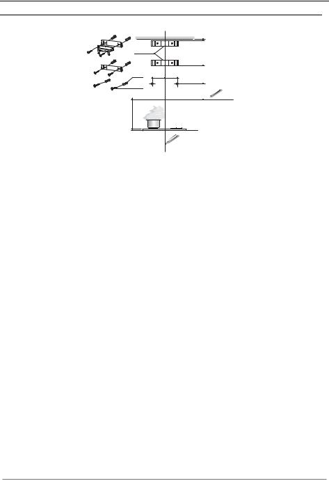
Wall drilling and bracket fixing
7.2.1
11 |
116 116 |
12a |
|
650 min.
340 X 1÷2
Wall marking:
•Draw a vertical line on the supporting wall up to the ceiling, or as high as practical, at the centre of the area in which the hood will be installed.
•Draw a horizontal line at 650 mm above the hob.
•Place bracket 7.2.1 on the wall as shown about 1-2 mm from the ceiling or upper limit aligning the centre (notch) with the vertical reference line.
•Mark the wall at the centres of the holes in the bracket.
•Place bracket 7.2.1 on the wall as shown at X mm below the first bracket (X = height of the upper chimney section supplied), aligning the centre (notch) with the vertical line.
•Mark the wall at the centres of the holes in the bracket.
•Mark a reference point as indicated at 116 mm from the vertical reference line and 340 mm above the horizontal reference line.
•Repeat this operation on the other side.
•Drill ø 8 mm holes at all the centre points marked.
•Insert the wall plugs 11 in the holes.
•Fix the lower bracket 7.2.1 using the 12a screws (4,2 x 44,4) supplied.
•Fix the upper bracket 7.2.1 and the air outlet connection support 7.3 together using the 2 screws 12a (4,2 x 44,4) supplied.
•Insert the two screws 12a (4,2 x 44,4) supplied in the hood body fixing holes, leaving a gap of 5-6 mm between the wall and the head of the screw.
EN |
|
5 |
|
5 |
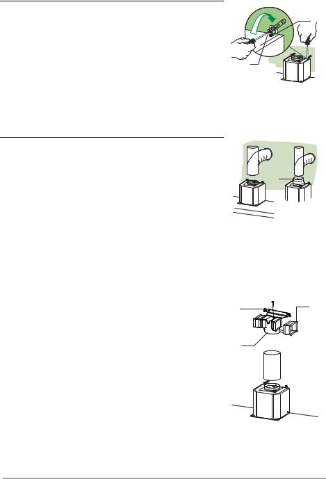
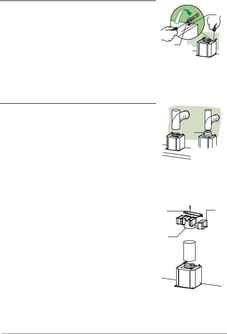
Mounting the hood body
•Before attaching the hood body, tighten the two screws Vr located on the hood body mounting points.
•Hook the hood body onto the screws 12a.
•Fully tighten the support screws 12a.
•Adjust the screws Vr to level the hood body.
Vr
12a
Connections
DUCTED VERSION AIR EXHAUST SYSTEM
When installing the ducted version, connect the hood to the chimney using either a flexible or rigid pipe ø 150 or 120 mm, the choice of which is left to the installer.
•To install a ø 120 mm air exhaust connection, insert the reducer flange 9 on the hood body outlet.
•Fix the pipe in position using sufficient pipe clamps (not supplied).
•Remove any activated charcoal filters.
RECIRCULATION VERSION AIR OUTLET
•Insert the connection extension pieces laterally 14.1 in connection 15.
•Insert the Connector 15 into the Support bracket 7.3 and fix it with a screw.
•Make sure that the outlet of the extension pieces 14.1 is horizontally and vertically aligned with the chimney outlets.
•Connect the air outlet connection 15 to the hood body outlet
using either a flexible or rigid pipe ø 150 mm, the choice of which is left to the installer.
• Ensure that the activated charcoal filters have been inserted.
ø 150 |
ø 120 |
9
7.3 |
14.1 |
|
|
15 |
|
|
ø 150 |
EN |
|
6 |
|
6 |
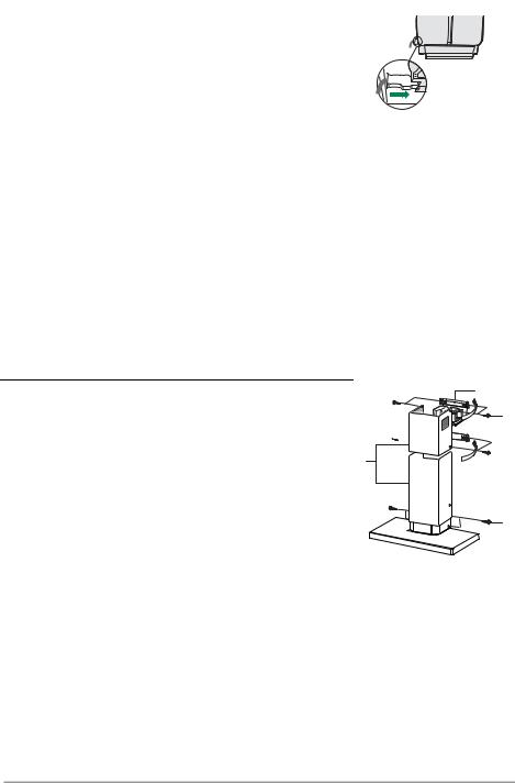
ELECTRICAL CONNECTION
•Connect the hood to the mains through a two-pole switch having a contact gap of at least 3 mm.
•Remove the grease filters (see paragraph Maintenance) being sure that the connector of the feeding cable is correctly inserted in the socket placed on the side of the fan.
Flue assembly
Upper exhaust flue
•Slightly widen the two sides of the upper flue and hook them behind the brackets 7.2.1, making sure that they are well seated.
•Secure the sides to the brackets by using the 4 screws 12c (2,9 x 9,5) supplied.
•Make sure that the outlet of the extensions pieces is aligned with the chimney outlets.
Lower exhaust flue
• Slightly widen the two sides of the flue and hook them between the upper flue and the wall, making sure that they are well seated.
•Fix the lower part laterally to the hood body by using the 2 screws 12c (2,9 x 9,5) supplied.
7.2.1
12c |
2.1 
 2
2 
2.2
12c
EN |
|
7 |
|
7 |

USE
|
|
|
|
|
|
|
|
|
|
|
|
|
|
|
|
|
|
|
|
|
|
|
|
|
|
A |
|
B |
C |
D |
E |
F |
G |
H |
|||||||||||||||
|
|
|
|
|
|
|
|
|
|
|
|
|
|
Control panel |
|
|
|
|
|
|
|
|
|
|
|
Button |
|
Function |
|
|
|
|
|
|
|
Display |
|
|
|
|
|
|
|
|
|
||||
|
A |
|
Turns the suction motor on and off at speed one. |
Displays the set speed |
|
|
|
|
|
|
|
|
|
|||||||||||
|
B |
|
Decreases the working speed. |
Displays the set speed |
|
|
|
|
|
|
|
|
|
|||||||||||
|
C |
|
Increases the working speed. |
Displays the set speed |
|
|
|
|
|
|
|
|
|
|||||||||||
|
D |
|
Activate intensive speed from any other speed, |
Displays HI and the time remaining once very second. |
|
|||||||||||||||||||
|
|
|
|
|
including motor off. This speed is set to operate |
|
|
|
|
|
|
|
|
|
|
|||||||||
|
|
|
|
|
for 10 minutes, after which the system returns to |
|
|
|
|
|
|
|
|
|
|
|||||||||
|
|
|
|
|
the speed that was set before. Suitable to deal with |
|
|
|
|
|
|
|
|
|
|
|||||||||
|
|
|
|
|
maximum levels of cooking fumes. |
|
|
|
|
|
|
|
|
|
|
|||||||||
|
|
|
|
|
Press and hold the button for approximately 5 |
FC+Punto (2 flashes)–Alarm On. |
|
|
|
|
|
|
||||||||||||
|
|
|
|
|
seconds, with all the loads turned off (Motor and |
FC+Punto (1 flash)–Alarm Off. |
|
|
|
|
|
|
||||||||||||
|
|
|
|
|
Lights), to turn the Activated Charcoal Filter |
|
|
|
|
|
|
|
|
|
|
|||||||||
|
|
|
|
|
alarm On and Off. |
|
|
|
|
|
|
|
|
|
|
|
|
|
||||||
|
E |
|
24H function |
|
|
|
|
|
|
|
Displays 24 and the spot at the bottom right flashes once |
|
||||||||||||
|
|
|
|
|
Turns the suction motor on at speed one and |
every second, while the motor is running. |
|
|
|
|
|
|
||||||||||||
|
|
|
|
|
effects one 10 minute extraction every hour. |
It is disabled by pressing the button. |
|
|
|
|
|
|
||||||||||||
|
|
|
|
|
When the filters alarm is triggered, the alarm can |
FF flashes three times. |
|
|
|
|
|
|
|
|
|
|||||||||
|
|
|
|
|
be reset by pressing and holding this button for |
|
|
|
|
|
|
|
|
|
|
|||||||||
|
|
|
|
|
approximately 3 seconds. |
|
|
|
|
|
|
|
|
|
|
|
|
|
||||||
|
|
|
|
|
These indications are only visible when the motor |
When the procedure terminates, the indication shown |
|
|||||||||||||||||
|
|
|
|
|
is turned off. |
|
|
|
|
|
|
|
previously turns off: |
|
|
|
|
|
|
|
|
|
||
|
|
|
|
|
|
|
|
|
|
|
|
|
|
|
FG indicates the need to wash the metal grease filters. |
|
||||||||
|
|
|
|
|
|
|
|
|
|
|
|
|
|
|
The alarm is triggered after the Hood has been in |
|
||||||||
|
|
|
|
|
|
|
|
|
|
|
|
|
|
|
operation for 100 working hours. |
|
|
|
|
|
|
|||
|
|
|
|
|
|
|
|
|
|
|
|
|
|
|
FC indicates the need to change the activated charcoal |
|
||||||||
|
|
|
|
|
|
|
|
|
|
|
|
|
|
|
filters, and also to wash the metal grease filters. The alarm |
|
||||||||
|
|
|
|
|
|
|
|
|
|
|
|
|
|
|
is triggered after the Hood has been in operation for 200 |
|
||||||||
|
|
|
|
|
|
|
|
|
|
|
|
|
|
|
working hours. |
|
|
|
|
|
|
|
|
|
|
F |
|
Delay function |
|
|
|
|
|
|
|
|
|
|
|
|
|
|
|
|
|
||||
|
|
|
|
|
Activate automatic switch-off with a 30’ delay. |
Displays the operating speed and the spot at the bottom |
|
|||||||||||||||||
|
|
|
|
|
Suitable to complete elimination of residual |
right flashes once a second. |
|
|
|
|
|
|
|
|
|
|||||||||
|
|
|
|
|
odours. Can be activated from any position, and is |
|
|
|
|
|
|
|
|
|
|
|||||||||
|
|
|
|
|
disabled by pressing the button or turning the |
|
|
|
|
|
|
|
|
|
|
|||||||||
|
|
|
|
|
motor off. |
|
|
|
|
|
|
|
|
|
|
|
|
|
|
|
|
|
||
|
|
|
|
|
Press and hold the button for approximately 5 |
IR+Punto (2 flashes)–Alarm On. |
|
|
|
|
|
|
||||||||||||
|
|
|
|
|
seconds, with all the loads turned off (Motor and |
IR+Punto (1 flash)–Alarm Off. |
|
|
|
|
|
|
||||||||||||
|
|
|
|
|
Lights), to turn the Remote Control On and Off. |
|
|
|
|
|
|
|
|
|
|
|||||||||
|
G |
|
Turns the lighting system on and off at maximum |
|
|
|
|
|
|
|
|
|
|
|||||||||||
|
|
|
|
|
intensity. |
|
|
|
|
|
|
|
|
|
|
|
|
|
|
|
|
|
||
|
H |
|
Turns the Courtesy Lighting on and off. |
|
|
|
|
|
|
|
|
|
|
|||||||||||
|
|
|
|
|
|
|
|
|
|
|
|
|
|
|
|
|
|
|
|
|
|
|
|
|
EN |
|
8 |
|
8 |
MAINTENANCE
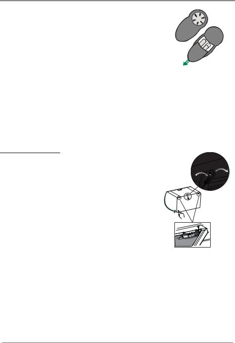
REMOTE CONTROL (OPTIONAL)
The appliance can be controlled using a remote control powered by a 1.5 V carbon-zinc alkaline batteries of the standard LR03AAA type (not included).
• Do not place the remote control near to heat sources.
• Used batteries must be disposed of in the proper manner.
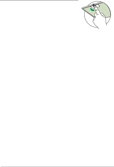
Cleaning the Comfort Panels
• Pull the Comfort Panel to open it. |
1 |
2 |
|
• |
Unhook the security chain by opening the spring catch. |
||
• |
Disconnect the panel from the hood canopy by sliding the fix- |
||
ing pin lever.
• The comfort panel must never be washed in a dishwasher.
• Clean the outside by using a damp cloth and neutral liquid detergent.
• Clean the inside as well by using a damp cloth and neutral detergent; do not use wet cloths or sponges, or jets of water; do not use abrasive substances.
• When the above operation has been completed, hook the panel back and the spring catch to the hood canopy and close it by turning the knob in the opposite direction.
EN |
|
9 |
|
9 |
Metal grease filters
They can be washed in the dishwasher, and need to be cleaned whenever the FG sign appears on the display or at least once every 2 months use, or more frequently if use is particularly intensive.
Resetting the alarm signal
•Turn the Lights and the Suction motor off, then disable the 24h function, if enabled.
•Press button E (see the paragraph on Use).
Cleaning the Filters
•Open the Comfort panels by pulling on the recess.
•Remove the Filters one at a time, pushing them towards the back of the unit and at the same time pulling downward.
•Wash the Filters without bending them, and leave them to dry completely before replacing. (If the surface of the filter changes colour as time goes by, this will have absolutely no effect on the efficiency of the filter itself.)
•Replace, taking care to ensure that the handle faces forwards.
•Close the Comfort panels.
EN |
|
1 |
|
10 |
Activated Charcoal Filter (Recirculation Version)
It cannot be washed or regenerated, and must be changed when the FC symbol on the display appears, or at least once every 4 months. The Alarm signal, if it has been activated, only appears when the Suction motor is turned on.
Activating the alarm signal
•In Recirculation Version Hoods, the Filter Saturation Alarm must be activated on installation or at a later date.
•Turn the Lights and the Suction Motor off.
•Press D and hold for approximately 5 Seconds:
•The message FC+Puntino flashes twice, A.C. Filter saturation alarm ACTIVATED
•The message FC+Puntino flashes once, A.C. Filter saturation alarm DEACTIVATED
CHANGING THE ACTIVATED CHARCOAL FILTER
Resetting the alarm signal
• Turn the Lights and the Suction motor off, then disable the 24h function, if enabled.
• Press button E (see the paragraph on Use).
Changing the Filter
• Open the Comfort panels by pulling on the recess.
•Remove the Metal grease filters.
•Remove the saturated charcoal filter by releasing the fixing hooks.
•Fit the new filter and fasten it in its correct position.
•Replace the Metal grease filters.
•Close the Comfort panels.
Lighting
LIGHT REPLACEMENT
20 W halogen light.
• Remove the snap-on lamp cover by levering it from under the metal ring, supporting it with one hand.
• Remove the halogen lamp from the lamp holder by pulling gently.
• Replace the lamp with a new one of the same type, making sure that you insert the two pins properly into the housings on the lamp holder.
• Replace the snap-on lamp cover.
EN |
|
1 |
|
11 |
CONSIGLI E SUGGERIMENTI
 Questo libretto di istruzioni per l'uso è previsto per più versioni dell' apparecchio. É possibile che siano descritti singoli particolari della dotazione, che non riguardano il Vostro apparecchio.
INSTALLAZIONE
•Il produttore declina qualsiasi responsabilità per danni dovuti ad installazione non corretta o non conforme alle regole dell’arte.
•La distanza minima di sicurezza tra il Piano di cottura e la Cappa deve essere di 650 mm, (alcuni modelli possono essere installati ad un’altezza inferiore, fare riferimento ai paragrafi ingombro e installazione).
•Verificare che la tensione di rete corrisponda a quella riportata nella targhetta posta all’interno della Cappa.
•Per Apparecchi in Classe Ia accertarsi che l’impianto elettrico domestico garantisca un corretto scarico a terra.
•Collegare la Cappa all’uscita dell’aria aspirata con tubazione di diametro pari o superiore a 120 mm. Il percorso della tubazione deve essere il più breve possibile.
•Non collegare la Cappa a condotti di scarico dei fumi prodotti da combustione (caldaie, caminetti, ecc.).
•Nel caso in cui nella stanza vengano utilizzati sia la Cappa che apparecchi non azionati da energia elettrica (ad esempio apparecchi utilizzatori di gas), si deve provvedere ad una aerazione sufficiente dell’ambiente. Se la cucina ne fosse sprovvista, praticare un’apertura che comunichi con l’esterno, per garantire il richiamo d’aria pulita. Un uso proprio e senza rischi si ottiene quando la depressione massima del locale non supera i 0,04 mBar.
•In caso di danneggiamento del cavo alimentazione, esso deve essere sostituito dal costruttore o dal servizio di assistenza tecnica, in modo da prevenire ogni rischio.
•Se le istruzioni di installazione del dispositivo di cottura a gas indicano che è necessaria una distanza maggiore di quella indicato sopra, è necessario tenerne conto. Bisogna rispettare tutte le normative relative allo scarico dell’aria.
USO
•La Cappa è stata progettata esclusivamente per uso domestico, per abbattere gli odori della cucina.
•Non fare mai uso improprio della Cappa.
•Non lasciare fiamme libere a forte intensità sotto la Cappa in funzione.
•Regolare sempre le fiamme in modo da evitare una evidente fuoriuscita laterale delle stesse rispetto al fondo delle pentole.
•Controllare le friggitrici durante l’uso: l’olio surriscaldato potrebbe infiammarsi.
•Non preparare alimenti flambè sotto la cappa da cucina; pericolo d'incendio.
•Questo apparecchio non deve essere utilizzato da persone (bambini inclusi) con ridotte capacità psichiche, sensoriali o mentali, oppure da persone senza esperienza e conoscenza, a meno che non siano controllati o istruiti all’uso dell’apparecchio da persone responsabili della loro sicurezza.
•I bambini devono essere supervisionati per assicurarsi che non giochino con l’apparecchio.
•“ATTENZIONE: Le parti accessibili possono diventare molto calde se utilizzate con degli apparecchi di cottura”.
MANUTENZIONE
•Prima di procedere a qualsiasi operazione di manutenzione, disinserire la Cappa togliendo la spina elettrica o spegnendo l’interruttore generale.
•Effettuare una scrupolosa e tempestiva manutenzione dei Filtri secondo gli intervalli consigliati (Rischio di incendio).
•Per la pulizia delle superfici della Cappa è sufficiente utilizzare un panno umido e detersivo liquido neutro.
Il simbolo  sul prodotto o sulla confezione indica che il prodotto non deve essere considerato come un normale rifiuto domestico, ma deve essere portato nel punto di raccolta appropriato per il riciclaggio di apparecchiature elettriche ed elettroniche. Provvedendo a smaltire questo prodotto in modo appropriato, si contribuisce a evitare potenziali conseguenze negative per l’ambiente e per la salute, che potrebbero derivare da uno smaltimento inadeguato del prodotto. Per informazioni più dettagliate sul riciclaggio di questo prodotto, contattare l’ufficio comunale, il servizio locale di smaltimento rifiuti o il negozioin cui è stato acquistato il prodotto.
IT
2°
1
12
CARATTERISTICHE
Ingombro
Componenti
Rif. Q.tà Componenti di Prodotto
11 Corpo Cappa completo di: Comandi, Luce, Gruppo Ventilatore, Filtri
2 |
1 |
Camino Telescopico formato da: |
2.1 |
1 |
Camino Superiore |
2.2 |
1 |
Camino Inferiore |
9 |
1 |
Flangia di Riduzione ø 150-120 mm |
14.1 |
2 |
Prolunga Raccordo Uscita Aria |
15 |
1 |
Raccordo Uscita Aria |
Rif. |
Q.tà |
Componenti di Installazione |
7.2.1 |
2 |
Staffe Fissaggio Camino Superiore |
7.3 |
1 |
Staffa Sostegno Raccordo |
11 |
6 |
Tasselli |
12a |
6 |
Viti 4,2 x 44,4 |
12c |
6 |
Viti 2,9 x 9,5 |
|
Q.tà |
Documentazione |
|
1 |
Libretto Istruzioni |
15
14.1
7.3 |
12a |
7.2.1 |
11 |
|
9
2.1 |
12c |
|
2
2.2
11 |
12a |
1
IT |
|
1 |
|
13 |

INSTALLAZIONE
Foratura Parete e Fissaggio Staffe
7.2.1
11 |
116 |
116 |
12a |
|
|
650 min.
340 X 1÷2
Tracciare sulla Parete:
•una linea Verticale fino al soffitto o al limite superiore, al centro della zona prevista per il montaggio della Cappa;
•una linea Orizzontale a: 650 mm min. sopra il Piano di Cottura.
•Appoggiare come indicato la Staffa 7.2.1 a 1-2 mm dal soffitto o dal limite superiore, allineando il suo centro (intagli) sulla linea Verticale di riferimento.
•Segnare i centri dei Fori della Staffa.
•Appoggiare come indicato la Staffa 7.2.1 a X mm sotto la prima staffa (X = altezza Camino Superiore in dotazione), allineando il suo centro (intagli) sulla linea Verticale di riferimento.
•Segnare i centri dei Fori della Staffa.
•Segnare come indicato, un punto di riferimento a 116 mm dalla linea Verticale di riferimento, e 340 mm sopra la linea Orizzontale di riferimento.
•Ripetere questa operazione dalla parte opposta.
•Forare ø 8 mm i punti segnati.
•Inserire i tasselli 11 nei fori.
•Fissare la Staffa inferiore 7.2.1 utilizzando le Viti 12a (4,2 x 44,4 ) in dotazione.
•Fissare insieme la Staffa superiore 7.2.1 e la Staffa sostegno raccordo 7.3 utilizzando le 2 viti 12a (4,2 x 44,4) in dotazione.
•Avvitare 2 Viti 12a (4,2 x 44,4) in dotazione nei fori per il fissaggio del corpo Cappa, lasciando uno spazio di 5-6 mm fra la parete e la testa della vite.
IT |
|
1 |
|
14 |
Montaggio Corpo Cappa
•Prima di agganciare il Corpo Cappa, serrare le 2 Viti Vr situate sui punti di aggancio del Corpo Cappa.
•Agganciare il Corpo Cappa alle Viti 12a.
•Serrare definitivamente le Viti 12a di supporto.
•Agire sulle Viti Vr per livellare il Corpo Cappa.
Connessioni
USCITA ARIA VERSIONE ASPIRANTE
Per installazione in Versione Aspirante collegare la Cappa alla tubazione di uscita per mezzo di un tubo rigido o flessibile di ø150 o 120 mm, la cui scelta è lasciata all'installatore.
•Per collegamento con tubo ø120 mm, inserire la Flangia di riduzione 9 sull’Uscita del Corpo Cappa.
•Fissare il tubo con adeguate fascette stringitubo. Il materiale occorrente non è in dotazione.
•Togliere eventuali Filtri Antiodore al Carbone attivo.
Vr
12a
ø 150 |
ø 120 |
9
USCITA ARIA VERSIONE FILTRANTE
•Inserire lateralmente le Prolunghe Raccordo 14.1 sul Raccordo
15.
•Inserire il Raccordo 15 nella Staffa di Sostegno 7.3 fissandolo con una Vite.
•Assicurarsi che l’uscita delle Prolunghe Raccordo 14.1 risulti in corrispondenza delle bocchette del Camino sia in orizzontale che in verticale.
•Collegare il Raccordo 15 all’Uscita del Corpo Cappa per mezzo di un tubo rigido o flessibile di ø150 mm, la cui scelta è lasciata all'installatore.
•Assicurarsi della presenza del Filtro Antiodore al Carbone attivo.
7.3 |
14.1 |
|
|
15 |
|
|
ø 150 |
IT |
|
1 |
|
15 |
 Loading...