


NAZCA Centrale
NOTICE D’INSTALLATION ET D’UTILISATION
INSTRUCTIONS FOR INSTALLATION AND DIRECTIONS FOR USE
MONTAGEUND GEBRAUCHSANWEISUNG
LIBRETTO DI ISTRUZIONI
INSTRUCCIONES DE INSTALACION E UTILIZACION
MONTAGEEN GEBRUIKSHANDLEIDING

F |
SOMMAIRE |
|
GB CONTENTS |
RACCORDEMENT ÉLECTRIQUE |
ELECTRICAL WIRING |
||
CONSEILS D’INSTALLATIONS |
INSTALLATION ADVICE |
||
POSE DE L’APPAREIL |
FITTING THE APPLIANCE |
||
FONCTIONNEMENT |
OPERATION |
||
CONSEILS D’UTILISATIONS |
USEFUL HINTS |
||
ENTRETIEN |
MAINTENANCE |
||
GARANTIE ET SERVICE APRÈS-VENTE |
GUARANTEE AND AFTER-SALES-SERVICES |
||
REMARQUES |
REMARKS |
||
D |
INHALT |
|
I |
CONTENUTI |
|
|
|
||
NETZANSCHLUSS |
COLLEGAMENTO ELETTRICO |
|||
MONTAGEHILFEN |
CONSIGLI DI INSTALLAZIONE |
|||
MONTAGE DES GERÄTES |
POSA DELL’ APPARECCHIO |
|||
BETRIEB DES GERÄTES |
FUNZIONAMENTO |
|||
NUTZUNG |
CONSIGLI DI UTILIZZO |
|||
WARTUNG UND REINIGUNG |
MANUTENZIONE |
|||
GARANTIE UND KUNDENDIENST |
GARANZIA ED ASSISTENZA TECNICA |
|||
WICHTIGE HINVEISE |
NOTE |
|
||
E |
SUMARIO |
|
NL INHOUD |
CONEXION ELECTRICA |
ELECTRISCHE BEDRADING |
||
CONSEJOS DE INSTALACION |
MONTAGE AANWIJZING |
||
INSTALACION DEL APARATO |
AANSLUITEN VAN HET APPARAAT |
||
FUNCIONAMIENTO |
FUNKTIONEREN |
||
CONSEJOS DE UTILIZACION |
GEBRUIKSADVIES |
||
MANTENIMIENTO |
ONDERHOUD |
||
GARANTIA Y ASSISTENCIA TECNICA |
AFTER SALES SERVICE |
||
NOTA |
|
OPMERKINGEN |
|

F
Nous vous remercions de la confiance que vous nous avez accordée en choisissant un appareil de la gamme FRANKE.
Celui-ci a fait l’objet de toute notre attention dans sa conception et sa réalisation.
Afin qu’il vous donne entière satisfaction, nous vous recommandons de lire avec attention cette notice qui vous expliquera comment l’installer, l’utiliser et l’entretenir dans les meilleures conditions.
La présente notice d’emploi vaut pour plusieurs versions de l’appareil. Elle peut contenir des descriptions d’accessoires ne figurant pas dans votre appareil.
1 RACCORDEMENT ÉLECTRIQUE.
• La hotte est équipée d’un cordon d’alimentation de type HO5VVF 3 x 0,75 mm² comportant une fiche normalisée 10/16 A avec système de mise à la terre.
Mode de protection : classe I. Tension d’alimentation : 220-240 V mono - 50Hz / 220 V - 60Hz.
Vérifier que la tension du secteur est identique aux valeurs indiquées sur la plaque signalétique à l’intérieur de la hotte
• Si la hotte est raccordée directement sur le réseau sans sa fiche, un interrupteur omnipolaire avec une ouverture de contact de 3 mm doit être installé avant la hotte. Le fil de terre (Jaune / vert) ne doit pas être interrompu par cet interrupteur.
2 CONSEILS D’INSTALLATION.
•Pour un fonctionnement idéal, nous vous conseillons une plage de hauteur de pose qui se situe de 0,65 m à 0,70 m au-dessus du plan de cuisson. Toutefois, il est formellement interdit d’installer toute hotte ou groupe d’aspiration à une distance inférieure à 0,65 m du plan de travail (risque d’inflammation des filtres). La fumée doit monter naturellement vers la zone de captation.
•Respecter le diamètre de sortie de l’appareil : la hotte ne doit en aucun cas être raccordée à un conduit de ventilation mécanique contrôlée (V.M.C.).
•Lorsqu’on évacue l’air vicié dans un conduit d’évacuation, veiller à ce que celui-ci ne soit pas déjà exploité à véhiculer des gaz ou fumées provenant d’appareils alimentés par une énergie autre qu’électrique.
•Positionner le plan de cuisson au plus près de l’évacuation et éviter la formation de coudes sur la gaine, afin de réduire au maximum les pertes de charges.
•Dans tous les cas d’installation, veiller au bon renouvellement d’air de la cuisine. Penser à effectuer une ou des entrées d’air par une grille de section égale ou supérieure au diamètre du tuyau d’évacuation, afin de ne pas mettre la cuisine en dépression.
•Prévoir une aération suffisante lorsqu’un appareil de cuisson ou autre utilise simultanément l’air ambiant de la pièce où est installée la hotte.
•La dépression maximum crée dans la pièce doit être inférieur à 0.04 mbar, ce qui évite un retour de gaz de combustion.
•L’appareil doit être positionné de telle façon que la fiche d’alimentation soit accessible.
•Cet appareil ne doit pas être utilisé par des personnes (y compris les enfants) ayant des capacités psychiques, sensorielles ou mentales réduites, ni par des personnes n’ayant pas l’expérience et la connaissance de ce type d’appareils, à moins d’être sous le contrôle et la formation de personnes responsables de leur sécurité.
Les enfants doivent être surveillés pour s’assurer qu’ils ne jouent pas avec l’appareil.
1

F
3 POSE DE L’APPAREIL.
Montage et raccordement doivent être réalisés par un installateur* qualifié.
(*) Le non-respect de cette condition entraîne la suppression de la garantie du constructeur et tout recours en cas d’accident.
Attention: prendre bien soin d’employer les chevilles adaptées au support, se renseigner au près des fabricants, effectuer un scellement si nécessaire. La société décline toute responsabilité en cas d’accrochage défectueux dû au perçage et chevillage au plafond.
1)Ouvrir le colis de la hotte.
•PERCAGE DU PLAFOND
2)A l’aide d’un fil à plomb reporter au plafond le centre du plan de cuisson. Tracer les axes parallèlement au plan de cuisson (Fig. 1).
3)Positionner le gabarit de perçage en alignant les axes tracés et le centre avec ceux du gabarit . Tracer les centres des différents perçages à effectuer. (Fig 2b)
4)Enlever les vis du conduit (Fig. 2a), puis enlever le support de hotte du conduit d’habillage Rep. 7.
5)Débrancher le connecteur, puis enlever les vis TH 5 x 16 qui fixent la boîte moteur sur le corps.
•FIXATION DU SUPPORT DE HOTTE
6)Percer le plafond à l’endroit de la pose, dont un trou de Ø 40 qui permet le passage de l’alimenta-
tion suivant la Fig. 2b. Si le plafond est en béton, employer 4 chevilles en fonte pour Ø 10, exclure les chevilles en plastique. Si celui-ci vous semble de solidité douteuse, n’hésitez pas à le renforcer dans les combles (Fig. 3). Fixer solidement le support de hotte à l’aide de 4 tiges filetées Ø 10 mm.
7)Déposer le diffuseur (Fig. 4).
8)Fixer la boîte moteur sur le support de hotte à la hauteur désirée. Votre hotte est réglable en hauteur par tranche de 50 mm ; les 8 vis 5 x 10 T. Hexagonale se logent dans les trous oblongs permettant une mise à l’aplomb. (Fig. 5). L’orientation des commandes est représentée sur le gabarit.
9)Vérifier l’aplomb du conduit.
•RACCORDEMENT
•Version Evacuation Extérieure :
a- Mettre le clapet anti retour C sur la sortie de l’appareil (Rep. 6) et raccorder le tuyau flexible
à l’évacuation extérieure et à la sortie de l’appareil. Fixer l’ensemble à l’aide de colliers ou de ruban adhésif appropriés (Fig. 8).
b- Raccorder électriquement la hotte (Voir paragraphe Raccordement Electrique).
c- Monter la partie supérieure du conduit Rep. 7 sur le support de hotte. Puis le fixer par leurs vis (Fig. 2a)
d- Vérifier de nouveau l’aplomb du conduit.
e- Enfiler la partie inférieure Rep. 5 sur la partie supérieure du conduit. La maintenir en position en dévissant légèrement 2 vis du conduit supérieur. (Fig. 9)
• Version Recyclage :
a- Fixer le déflecteur R sur le support de conduit.
b- Installer un tuyau de diamètre approprié (Non fourni) entre la sortie de l’appareil (Rep. 6) et l’entrée du déflecteur. Fixer l’ensemble à l’aide de colliers ou de ruban adhésif appropriés (Fig. 6).
c- Raccorder électriquement la hotte (Voir paragraphe Raccordement Electrique).
d- Monter la partie supérieure du conduit Rep. 7 sur le support de hotte. Puis le fixer par leurs vis (Fig. 2a)
e- Vérifier de nouveau l’aplomb du conduit.
f- Enfiler la partie inférieure Rep. 5 sur la partie supérieure du conduit. La maintenir en position en dévissant légèrement 2 vis du conduit supérieur. (Fig. 9)
• POSE DU PLATEAU DE HOTTE
10)Présenter le plateau sous le conduit et le fixer avec les 6 vis TH 5X16 fournies. (Fig. 10)
Attention : Cette phase du montage doit être réalisée à 2 personnes compte tenu du poids et de la forme dissymétrique de la hotte.
11)Revisser les vis du conduit supérieur et abaisser le conduit inférieur Rep. 5.
2

F
12)Connecter le connecteur du plateau, vérifier les connecteurs du moteur et remettre le cache. (Fig.
13)Vérifier le bon fonctionnement de l’éclairage, du moteur et du changement des vitesses d’aspiration.
14)Pour les versions Recyclage : Placer la cartouche à charbon actif dans son logement en exerçant une pression sur les languettes A (Fig. 6)
15)Placer les filtres métalliques.
3
F
4 FONCTIONNEMENT
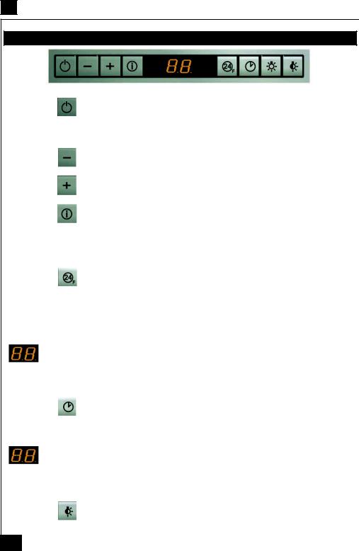
Tableau de commande |
|
|
Touche |
: |
Marche / Arrêt |
Allume et éteint le moteur d'aspiration à la dernière vitesse utilisée.
 Affiche la vitesse choisie.
Touche |
: |
Réglage vitesse |
Diminue la vitesse de service.
Touche |
: |
Réglage vitesse |
Augmente la vitesse de service.
Touche |
: |
Vitesse intensive |
Active la vitesse intensive à partir de n'importe quelle vitesse, même du moteur arrêter. cette vitesse est programmer pour durer 10 minutes, après quoi le système retourne à la vitesse réglée au préalable. Sert à faire face à une quantité maximale de fumées de cuisson.
 Affiche HI et le point bas à droite clignote une fois par seconde.
Touche |
: |
Renouvellement d'air |
Active le moteur à une vitesse permettant une aspiration de100 m3/h pendant 10 minutes toutes les heures, puis le moteur s'arrête.
 Affiche 24 et le point en bas à droite clignote, quand le moteur fonctionne.
Quand l'alarme filtres est déclenchée, appuyer sur cette touche pendant 3 secondes environ pour remettre l'alarme à l'état initial. Ces indications sont visibles uniquement quand le moteur est éteint.
En fin de procédure, le signal affiché précédemment s'éteint :
FF indique qu'il faut laver les filtres à graisse métalliques. L'alarme se déclenche après 100 heures de fonctionnement effectif de la hotte.
EF indique qu'il faut remplacer les filtres au charbon actif et laver les filtres à graisse métalliques. L'alarme se déclenche après 200 heures de fonctionnement effectif de la hotte.
Touche |
: |
Arrêt différé 30 minutes |
Active l'arrêt automatique retardé de 30 minutes. Utile pour achever d'éliminer toute odeur résiduelle.
S'active depuis toutes les positions et se désactive en appuyant sur la touche ou en éteignant le moteur.
Affiche tour à tour la vitesse de service et le temps restant avant l'arrêt de la hotte. le point en bas à droite clignote.
Touche  : Lumière
Allume et éteint l'éclairage. |
|
|
Touche |
: |
Réduction lumière |
Allume et éteint l'éclairage à intensité réduite
4

F
5 CONSEILS D’UTILISATION.
•Pour obtenir une efficacité maximum d’absorption des fumées ou des vapeurs, faire fonctionner l’appareil 5 minutes environ avant et après la cuisson des aliments; La première vitesse est conseillée pour les cuissons à feu doux et pour les sauces. La deuxième pour les cuissons soutenues, grillades et friteuses. La troisième est indiquée pour les cuissons à forte émanation de graisses et vapeur.
•IMPORTANT . NE JAMAIS FLAMBER DE METS AU DESSOUS DE L’APPAREIL
Ne laissez jamais de flammes libres sous la hotte en fonctionnement.
•Les fritures nécessitent une surveillance permanente, l’huile surchauffée pouvant s’enflammer.
6 ENTRETIEN.
Déconnecter le câble d’alimentation pour toute intervention électrique.
L’appareil a été conçu pour faciliter au maximum les opérations d’entretien, synonyme de bon fonctionnement et rendement de l’appareil dans le temps.
•Nettoyage des filtres métalliques.
Il est indispensable de procéder à un NETTOYAGE PÉRIODIQUE de ces filtres à la main (avec un détergent liquide à l’eau tiède et rinçage) ou au lavevaisselle (tous les deux mois environ pour une utilisation normale).
•Carrosserie.
Nettoyer régulièrement celle-ci en utilisant des produits détergents, non abrasifs et une éponge légèrement humide. N’utilisez jamais d’éponges ou de chiffons trempés
N’introduisez aucun objet, ni les mains dans l’ouverture servant à l’évacuation de l’air
•Conduit d’évacuation.
Vérifier tous les 6 mois le bon écoulement de l’air vicié.
Observer les prescriptions réglementaires locales concernant l’évacuation de l’air vicié.
•Éclairage.
Avant toute intervention sur l’appareil, mettre l’interrupteur d’allumage des lampes en position éteinte.
Ne pas dépasser la puissance prescrite et ne pas changer de type de lampe.
•Télécommande.
Attention, la télécommande doit être équipée de piles alcalines standards : LR003-AAA, 1.5V. Ces piles devraient assurer un usage optimum de longue durée et doivent être positionnées correc-tement, elles peuvent exploser si elles sont endommagées ou exposées à la chaleur. Ne pas les jeter dans le feu. Afin de préserver l’environnement, merci de déposer ces piles dans un conteneur approprié.
7 GARANTIE ET SERVICE APRÈS-VENTE.
•En cas d’anomalie de fonctionnement, prévenez votre installateur qui devra vérifier l’appareil et son raccordement.
•Dans le cas où un composant électrique viendrait à être endommagé, celui-ci ne peut être remplacé que par un atelier de réparation reconnu par le fabricant, car des outils spéciaux sont nécessaires.
•Débrancher complètement l’appareil.
•Exigez toujours l’utilisation de pièces de rechange d’origine. La non observation de cette prescription peut compromettre la sécurité de l’appareil.
•Lors de la commande de pièces détachées, rappeler le numéro de l’appareil inscrit sur la plaque signalétique située à l’intérieur de la hotte.
•Seule la facture d’achat de l’appareil fera foi pour l’application de la garantie contractuelle.
5

F
Cette garantie ne couvre pas les consommables comme :
-L’éclairage : lampes incandescentes, halogènes ...
-Les filtres.
8 REMARQUES.
Cet équipement est conforme à la norme européenne sur la basse tension 2006/95/CE relative à la sécurité électrique et aux normes européennes: 2004/108/CE relative à la compatibilité électromagnétique et 93/68 relative au marquage CE.
Lorsque ce symbole  d’une poubelle à roue barrée est attaché à un produit, cela signifie que le produit est couvert par la Directive Européenne 2002/96/EC. Votre produit est conçu et fabriqué avec des matériaux et des composants de haute qualité, qui peuvent être recyclés et utilisés de nouveau. Veuillez vous informer du système local de séparation des déchets électriques et électroniques. Veuillez agir selon les règles locales et ne pas jeter vos produits usagés avec les déchets domestiques usuels.
Jeter correctement votre produit usagé aidera à prévenir les conséquences négatives potentielles contre l’environnement et la santé humaine.
6

GB
Thank you for buying a FRANKE product which has been manufactured to the highest quality standards to meet your requirements.
We recommend you carefully read this booklet in which you will find instructions for installation, hints for use and maintenance.
The Instructions for Use apply to several versions of this appliance. Accordingly, you may find descriptions of individual features that do not apply to your specific appliance.
1 ELECTRICAL
• This cooker hood is fitted with a 3-core mains cable with a standard 10/16A earthed plug.
• Alternatively the hood can be connected to the mains supply via a double-pole switch having 3mm minimum contact gap on each pole.
• Before connecting to the mains supply ensure that the mains voltage corresponds to the voltage on the rating plate inside the cooker hood.
• Technical Specification: Voltage 220-240 V, single phase ~ 50 Hz / 220 V - 60Hz.
2 INSTALLATION ADVICE
•Ensure the cooker hood is fitted in compliance with the recommended fixing heights.
•To ensure the safe operation of this cooker hood, we recommend that the hood should not be fitted below 65cm (for electric) or (70cm for gas) the measurements taken from the surface of the cooking appliance to the underside of the cooker hood.
•It is a possible fire risk if the hood is not sited as recommended.
•To ensure the best results, the cooking fumes should be able to rise naturally towards the inlet grilles on the underside of the cooker hood and the cooker hood should be positioned away from doors and windows, which will create turbulence.
•Ducting
•If the room where the hood is to be used contains a fuel-burning appliance such as a central heating boiler then its flue must be of the room sealed or balanced flue type.
•If other types of flue or appliances are fitted ensure that there is an adequate supply of fresh air to the room. Ensure the kitchen is fitted with an airbrick, which should have a cross-sectional measurement equivalent to the diameter of the ducting being fitted, if not larger.
•The ducting system for this cooker hood must not be connected to any existing ventilation system, which is being used for any other purposes or to a mechanically controlled ventilation ducting.
•The ducting used must be made from fire retardant materials and the correct diameter must be used, as incorrect sized ducting will affect the performance of this cooker hood.
•When the cooker hood is used in conjunction with other appliances supplied with energy other than electricity, the negative pressure in the room must not exceed 0.04 mbar to prevent the fumes from combustion being drawn back into the room.
•The appliance is for domestic use only and should not be operated by children or people who are infirm without supervision.
•This appliance must be positioned so that the wall socket is accessible.
•This appliance is not intended for use by persons (including children) with reduced physical, sensory or mental capabilities, or lack of experience and knowledge, unless they have been given supervision or instruction concerning use of the appliance by a person responsible for their safety.
Children should be supervised to ensure that they do not play with the appliance.
3 FITTING
Any permanent electrical installation must comply with the latest regulations concerning this type of installation and a qualified electrician must carry out the work. Non-compliance could cause serious accidents or injury and would deem the manufacturers guarantee null and void.
IMPORTANT - The wires in this mains lead are coloured in accordance with the following code :
green / yellow : earth |
blue : neutral |
brown : live |
As the colours of the wires in the mains lead of this appliance may not correspond with the coloured
7
GB
markings identifying the terminals in your plug, proceed as follows.
-The wire which is coloured green and yellow must be connected to the terminal in the plug which is
marked with the letter E or by the earth symbol |
or coloured green or green and yellow. |
-The wire which is coloured blue must be connected to the terminal which is marked with the letter N or coloured black.
-The wire which is coloured brown must be connected to the terminal which is marked with the letter
L or coloured red.
ATTENTION: Do not forget to use adequate plugs to the support brackets. Enquire after the manufacturers. Do an embedding if necessary. The manufacturer accepts no responsibility in case of a faulty hanging due to the drilling and the setting up of plugs in the ceiling.
1) Unpack the hood parcel.
• LAYING OUT BEFORE FITTING THE HOOD
2)Mark the centre of the cooking appliance onto the ceiling with a plumb line. Draw the horizontal axes running parallel to the stove top onto the ceiling as illustrated Fig. 1.
3)Place the drill gauge centred on the axes aligning the axes on the drill gauge centrally over these axes as illustrated Fig. 2b.
4)Remove the self-tapping screws, which fix the chimney item 7 to the metal frame bracket as illustrated in Fig. 2a and then remove both sides of the upper chimney stacks.
5)Unplug the connector and separate the motor housing from the canopy unscrewing the screws TH 5 x 16.
• FITTING THE CANOPY BRACKET
6) Mark the positions on the ceiling for : - The cut-out for the ducting Ø 150 mm in the extraction mode and Ø 200 mm in the remote mode when ducting runs through the ceiling.
-The mains supply cords.
-The 4 fixing holes for Ø 10 mm nuts and bolts.
Drill the different holes with the appropriate masonry bit. When fixing the cooker hood to a plasterboard ceiling ensure it is reinforced as illustrated in Fig. 3 and attach using four Ø10mm nuts and bolts; ensuring the bolts as sleeved between the plasterboard and the joist supports to prevent the ceiling being damaged when the bolts are tightened up.
If the ceiling is concrete, use eight Ø 10 mm steel rawl bolts. Plastic rawl plugs must not be used.
7)Remove the deflector Fig. 4.
8)The height of the cooker hood can be adjusted in 50 mm stages. 650 mm when fitting above an electric hotplate and 700 mm when fitting above a gas hotplate. Select the height required using the measurements illustrated in Fig. 5 and fix the metal diffuser to the frame of the chimney brackets using the height 5 x 10T hexagonal headed screws. A drawing on the drill gauge defines the positioning for the controls.
9)Check the vertical of the chimney.
• DUCTING
The hood is more effective when used in the extraction mode (ducted to the outside). When the cooker hood is ducted to the outside, charcoal filters are not required.
The ducting used must be 150 mm (6 INS), rigid circular pipe and must be manufactured from fire retardant material, produced to BS.476 or DIN 4102-B1. Wherever possible utilise rigid circular pipe which has a smooth interior, rather than the expanding concertina type ducting.
Maximum length of ducting run:
-4 metres with 1 x 90° bend.
-3 metres with 2 x 90° bends.
-2 metres with 3 x 90° bends.
The above assumes our 150 mm (6 INS) ducting is being installed. Please note ducting components and ducting kits are optional accessories and have to be ordered, they are not automatically supplied with the chimney hood.
IN THE EXTRACTION MODE:
a. Fit the non-return backflow flaps C over the round outlet item 6 on top of the canopy while pressing down until they snap into position, and then connect the ducting 150mm (6 INS) and secure the connections with appropriate clamping rings or adhesive tape (Fig. 8).
8
GB
b.Before fitting the chimney to the canopy make the electrical connection as described in the section titled ELECTRICAL.
c.Each chimney stack consists of two sections. Fit the upper sections (Fig. 2a - item 7) first by expanding the chimneys slightly around the bracket and secure the chimney stacks to the brackets using the M4 screws provided.
d.Check the vertical of the chimney.
e.Pull on the lower chimney item 5 and secure it temporarily unscrewing a little bit the lower self tapping screws as illustrated in Fig 9.
IN THE RECIRCULATION MODE:
a.Fit the recirculation spigot R onto the chimney bracket using the same fixing screws.
b.Connect the ducting 150mm (6 INS) not provided between motors item 6 and the recirculation spigot and secure the connections with appropriate clamping rings or adhesive tape (Fig. 6).
c.Before fitting the chimney to the canopy make the electrical connection as described in the section titled ELECTRICAL.
d.Each chimney stack consists of two sections. Fit the upper sections (Fig. 2a - item 7) first by expanding the chimneys slightly around the bracket and secure the chimney stacks to the brackets using the M4 screws provided.
e.Check the vertical of the chimney.
f.Pull on the lower chimney item 5 and secure it temporarily unscrewing a little bit the lower self tapping screws as illustrated in Fig 9.
•FITTING THE CANOPY ONTO THE CHIMNEY
10)Place the canopy under the chimney and fix it with the 6 TH 5X16 screws provided as illustrated in
Fig. 10. Attention: 2 persons are necessary to secure this operation.
11)Screw the lower self tapping screws of the upper chimney and fit the lower chimney section item 5 by expending slightly it onto the canopy .
12)Connect the connector, check the connectors of the motor and place the cover as illustrated in Fig.
11.
13)Test the lights and the fan motor.
14)Remove the metal grease filters. Insert the charcoal filter into the base of the motor housing and secure the filter with two securing straps A as illustrated Fig. 6.
15)Fit the metal grease filters.
9

GB
4 OPERATION
Control board |
|
|
Key |
: |
On / Off |
Switches the extractor motor on and off at the latest selected speed.
Indicates the selected speed.
Key |
: |
Speed control |
Decreases the suction speed.
Key |
: |
Speed control |
Increases the suction speed.
Key |
: |
Intensive speed |
By pressing this key it is possible to activate the intensive speed from any previously se-lected speed.
The intensive speed can be acti-vated even when the motor is OFF. This speed has been timed at 10 minutes. After that time the system activates automatically the latest selected speed. This function is suitable for cooking conditions when vapours and smells are of the utmost emission.
HI appears. The spot down on the right side flashes once a second.
Key |
: |
Air Renewing |
By pressing this key it is possible to set up the motor to a suction speed at 100 m3/h lasting 10 minutes every hour. After this the motor switches off automatically.
Indicates the 24-function. The spot down on the right side flashes and the motor is on.
When the filter saturation is going on it is pos-sible to reset the alarm by pressing this key for about 3 seconds. The indication is visible only when the motor is off.
Once the process is finished the previous indi-cation disappears:
FF Indicates that the metal grease filters saturation alarm has been triggered, and the filters need to be washed. The alarm is triggered after 100 working hours.
EF Indicates that the charcoal filter satura-tion alarm has been triggered, and the fil-ter has to be replaced; the metal grease filters must also be washed. The charcoal filter is triggered after 200
working hours. |
|
|
Key |
: |
Stop delay 30 minutes |
By pressing this key it is possible to set the delayed shutdown of the appliance to 30 min-utes. This function is suitable for a complete elimination of the residual smells. It can be activated at any position, and it is deactivated by pressing the key again or by switching off the motor.
Indicates alternately the selected speed of the hood and the time left before the hood shutdown. The spot down on the right side flashes.
Key |
: |
Lighting |
Turns light on and off .
Key |
: |
Dimmer |
Turns light on and off at reduced intensity.
10

GB
5USEFUL HINTS
•To obtain the best performance we recommend you to switch ‘ON’ the cooker hood a few minutes (in the boost setting) before you start cooking and you should leave it running for approximately 15 minutes after finishing.
•IMPORTANT: NEVER DO FLAMBÉ COOKING UNDER THIS COOKER HOOD
•Do not leave frying pans unattended during use as over-heated fat and oil might catch fire.
•Do not leave naked flames under this cooker hood.
•Switch ‘OFF’ the electric and gas before removing pots and pans.
•Ensure heating areas on your hotplate are covered with pots and pans when using the hotplate and cooker hood simultaneously.
6 MAINTENANCE
Before carrying out any maintenance or cleaning isolate the cooker hood from the mains supply. The cooker hood must be kept clean; a build up of fat or grease may cause a fire hazard.
Casing
•Wipe the cooker hood frequently with a clean cloth, which has been immersed in warm water containing a mild detergent and wrung out.
•Never use excessive amounts of water when cleaning particularly around the control panel.
•Never use scouring pads or abrasive cleaners.
•Always wear protective gloves when cleaning the cooker hood.
Metal Grease Filters : The metal grease filters absorb grease and dust during cooking in order to keep clean the cooker hood inside. The grease filters should be cleaned once a month or more frequently if the hood is used for more than 3 hours per day.
To remove and replace the metal grease filters
•Remove the metal grease filters one at a time by releasing the catches on the filters; the filters can now be removed.
•The metal grease filters should be washed, by hand, in mild soapy water or in a dishwasher.
•Allow to dry before replacing.
Active Charcoal Filter : The charcoal filter cannot be cleaned. The filter should be replaced at least every three months or more frequently if the hood is used for more than three hours per day.
To remove and replace the filter
•Remove the metal grease filters.
•Press against the two retaining clips, which hold the charcoal filter in place and this will allow the filter to drop down and be removed.
•Clean the surrounding area and metal grease filters as directed above.
•Insert the replacement filter and ensure the two retaining clips are correctly located.
•Replace the metal grease filters.
Extraction tube : Check every 6 months that the dirty air is being extracted correctly. Comply with local rules and regulations with regard to the extraction of ventilated air.
Lighting : If the lamp fails to function check to ensure it is fitted correctly into the holder. If lamp failure has occurred then it should be replaced with identical replacement.
Do not replace with any other type of lamp and do not fit a lamp with a higher rating.
Remote control handset : Caution, the remote control handset must be fitted with standard LR03-AAA size 1.5V zinc-carbon alkaline batteries. These batteries should give a long life and constant discharge throughout their life. These batteries must be disposed of properly and could explode if damaged or exposed to heat. Do not dispose of on fire. Dispose of batteries in the appropriate sort
11
GB
7 GUARANTEE AND AFTER SALES SERVICE
•In the event of any malfunction or anomaly, notify your fitter who will have to check the appliance and its connection.
•In the event of damage to the mains supply cable, this can only be replaced by at approved repair centre appointed by the manufacturer who will have the required tools and equipment to carry out any repairs properly. Repairs carried out by other persons will invalidate the guarantee.
•Use only genuine spare parts. Should these warnings fail to be observed it could affect the safety of your cooker hood.
•When ordering spare parts quote the model number and serial number written on the rating plate, which is found on the casing behind the grease filters inside the hood.
•Proof of purchase will be required when requesting service. Therefore, please have your receipt available when requesting service as this constitutes the date from which your guarantee commenced.
This Guarantee does not cover :
- Damage or calls resulting from transportation, improper use or neglect, the replacement of any light bulbs or filters or removable parts of glass or plastic.
These items are considered to be consumable under the terms of this guarantee.
8REMARKS
This appliance complies with European regulations on low voltages Directive 2006/95/CE on electrical safety, and with the following European regulations: Directive 2004/108/CE on electromagnetic compatibility and Directive 93/68 on EC marking.
When this crossed-out wheeled bin symbol  is attached to a product it means the product is covered by the European directive 2002/96/EC.Your product is designed and manufactured with high quality materials and components, which can be recycled and reused.Please inform yourself about the local separate collection system for electrical and electronic product. Please act according to your local rules and do not dispose of your old products with your normal household waste. The correct disposal of your old product will help prevent potential negative consequences for the environment and human health.
12

D
Wir gratulieren Ihnen für das Vertrauen, welches Sie uns mit dem Kauf dieses FRANKE-Produktes entgegengebracht haben.
Dieses Gerät wurde nach dem neuesten Stand der Technik entwickelt und mit grösster Sorgfalt hergestellt.
Um eine problemlose und sichere Montage zu ermöglichen und die volle Zufriedenheit bei der Benutzung dieser Dunstesse zu erhalten, empfehlen wir Ihnen dringenst, sowohl die Montageanweisung sorgfältig zu beachten und die Gebrauchs-und Wartungshinweise aufmerksam zu lesen und anzuwenden. Bitte bewahren Sie diese Broschüre sorgfältig auf.
Diese Gebrauchsanleitung gilt für mehrere Geräte-Ausführungen. Es ist möglich, dass einzelne Ausstattungsmerkmale beschrieben sind, die nicht auf Ihr Gerät zutreffen.
1NETZANSCHLUSS
• Die Dunstabzugshaube ist mit einer Anschlussleitung der Art HO5VVF 3 x 0,75 mm2, die einen Schutzstecker 10 / 16 A enthält, ausgestattet. Das entspricht Schutzklasse 1.
Nennspannung : 220 - 240 V - Wechselstrom : 50 Hz / 220 V - 60 Hz.
•Es ist sicherzustellen, daß die Netzspannung den angegebenen Anschlusswerten auf dem
Typenschild im Inneren der Dunstesse entspricht.
•Beim Anschluss der Dunstesse an das Wechselstromnetz ist ein zweipoliger Schalter mit einem Öffnungsweg von wenigstens 3 mm für jeden Pol zwischenzuschalten.
2MONTAGEHILFEN
•Die Mindestund Höchstabstände zwischen der Dunstesse und der Kochfläche sind zu berücksichtigen. Wir empfehlen Ihnen einenAbstand von 650 mm bis 700 mm zwischen Filterfläche und Oberkante Kochfläche einzuhalten, um einen optimalen Betrieb des Gerätes zu gewährleisten. Jedoch ist es untersagt, Dunstessen oder Einbaugeräte mit einem Abstand, der niedriger als 650 mm ist, einzubauen (Entzündungsgefahr der Filter). Beachten Sie die richtige Ableitung der Kochschwaden (Luftzug kann Turbulenzen verursachen).
•Der Aussendurchmesser am Gebläseabgang des Gerätes ist für die Wahl des AbluftRohrsystems zu berücksichtigen : Die Dunstesse darf keinesfalls an eine Entlüftungsleitung mit
Unterdruck angeschlossen werden. Die Abluft darf nicht in einen Schornstein geleitet werden, der für die Abgase von Kochoder Heizgeräten, (Kohle-, Öl-, oder Gas-Öfen / -Herde) benutzt wird.
•Die Kochstelle (und damit auch die Dunstesse) unbedingt so planen und installieren, daß möglichst kurze Wege für eventuelleAbluft-Rohrleitungen erreicht werden. So wenig Umlenkungen [90°-Bögen] wie möglich vorsehen ! Keine Querschnittsverengungen vornehmen !
•Für eine ausreichende Belüftung zur Gewährleistung des Luftaustausches in der Küche ist zu sorgen. Nötigenfalls ist an einer Aussenwand eine entsprechende Öffnung anzubringen, die die Frischluftzufuhr gewährleistet.
•Sorgen Sie für eine ausreichende Zuluft, wenn z.B. ein gasbetriebenes Koch-oder anderes Gerät die Luft des Raumes, in dem die Dunstesse eingebaut ist, gleichzeitig verwendet. Ein gefahrloser Betrieb ist möglich, wenn bei gleichzeitigem Betrieb von Dunstesse und Feuerstätte im Raum ein Unterdruck von höchstens 0.04 mbar erreicht wird und ein Rücksaugen der Feuerstättenabgase vermieden wird.
Das Gerät muß so installiert werden, daß der Geräte-Stecker leicht erreichbar ist.
•Dieses Gerät darf nicht von Personen, auch Kindern, mit verminderten psychischen, sensorischen und geistigern Fähigkeiten, oder von Personen ohne Erfahrung und Kenntnisse benutzt werden, sofern sie nicht von für ihre Sicherheit verantwortlichen Personen beaufsichtigt und beim Gebrauch des Geräts angeleitet werden.
Kinder dürfen sich nicht unbeaufsichtigt in der Nähe des Geräts aufhalten und auf keinen Fall
mit dem Gerät spielen.
13
 Loading...