


GB
IT
FR
DE
TR
CZ
Instructions for use and installation
Cooker Hood
Istruzioni per l’uso e l’installazione
Cappa
Mode d’emploi et installation
Hotte de Cuisine
Bedienungsanleitung und Installation
Dunstabzugshaube
Kullanım ve montaj talimatları
Davlumbaz
Uživatelská Pøíruèka
Odsavač par
FTU 3807 I XS 77H V2

INDEX |
EN |
RECOMMENDATIONS AND SUGGESTIONS ..................................................................................................................... |
3 |
CHARACTERISTICS ............................................................................................................................................................. |
6 |
INSTALLATION...................................................................................................................................................................... |
8 |
USE ...................................................................................................................................................................................... |
12 |
MAINTENANCE ................................................................................................................................................................... |
13 |
INDICE |
IT |
CONSIGLI E SUGGERIMENTI............................................................................................................................................ |
15 |
CARATTERISTICHE............................................................................................................................................................ |
18 |
INSTALLAZIONE ................................................................................................................................................................. |
20 |
USO...................................................................................................................................................................................... |
24 |
MANUTENZIONE ................................................................................................................................................................ |
25 |
SOMMAIRE |
FR |
CONSEILS ET SUGGESTIONS.......................................................................................................................................... |
27 |
CARACTERISTIQUES......................................................................................................................................................... |
30 |
INSTALLATION.................................................................................................................................................................... |
32 |
UTILISATION ....................................................................................................................................................................... |
36 |
ENTRETIEN ......................................................................................................................................................................... |
37 |
INHALTSVERZEICHNIS |
DE |
EMPFEHLUNGEN UND HINWEISE ................................................................................................................................... |
39 |
CHARAKTERISTIKEN ......................................................................................................................................................... |
42 |
MONTAGE ........................................................................................................................................................................... |
44 |
BEDIENUNG ........................................................................................................................................................................ |
48 |
WARTUNG........................................................................................................................................................................... |
49 |
IÇERIKLER |
TR |
TAVSIYELER VE ÖNERILER.............................................................................................................................................. |
51 |
ÖZELLIKLER........................................................................................................................................................................ |
54 |
MONTAJ............................................................................................................................................................................... |
56 |
KULLANIM ........................................................................................................................................................................... |
60 |
BAKIM .................................................................................................................................................................................. |
61 |
OBSAH |
CZ |
RADY A DOPORUČENÍ ...................................................................................................................................................... |
63 |
HLAVNÍ PARAMETRY......................................................................................................................................................... |
66 |
INSTALACE ......................................................................................................................................................................... |
68 |
POUŽITÍ ............................................................................................................................................................................... |
72 |
ÚDRŽBA............................................................................................................................................................................... |
73 |
2
RECOMMENDATIONS AND SUGGESTIONS
 The Instructions for Use apply to several versions of this appliance. Accordingly, you may find descriptions of individual features that do not apply to your specific appliance.
INSTALLATION
•The manufacturer will not be held liable for any damages resulting from incorrect or improper installation.
•The minimum safety distance between the cooker top and the extractor hood is 650 mm (some models can
be installed at a lower height, please refer to the paragraphs on working dimensions and installation).
• Check that the mains voltage corresponds to that indicated on the rating plate fixed to the inside of the hood.
• For Class I appliances, check that the domestic power supply guarantees adequate earthing.
Connect the extractor to the exhaust flue through a pipe of minimum diameter 120 mm. The route of the flue must be as short as possible.
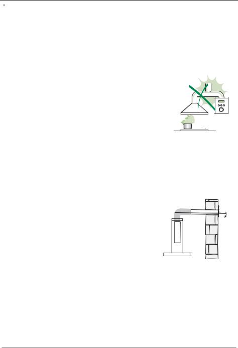
•Do not connect the extractor hood to exhaust ducts carrying combustion fumes (boilers, fireplaces, etc.).
•If the extractor is used in conjunction with non-
electrical appliances (e.g. gas burning appli- |
|
ances), a sufficient degree of aeration must be |
2° |
guaranteed in the room in order to prevent the |
|
backflow of exhaust gas. The kitchen must have |
|
an opening communicating directly with the open |
|
air in order to guarantee the entry of clean air. |
|
When the cooker hood is used in conjunction with |
|
appliances supplied with energy other than electric, the negative pressure in the room must not exceed 0,04 mbar to prevent fumes being drawn back into the room by the cooker hood.
•In the event of damage to the power cable, it must be replaced by the manufacturer or by the technical service department, in order to prevent any risks.
EN |
|
3 |
|
3 |

•If the instructions for installation for the gas hob specify a greater distance specified above, this has to be taken into account. Regulations concerning the discharge of air have to be fulfilled.
•Use only screws and small parts in support of the hood.
Warning: Failure to install the screws or fixing device in accordance with these instructions may result in electrical hazards.
•Connect the hood to the mains through a two-pole switch having a contact gap of at least 3 mm.
USE
•The extractor hood has been designed exclusively for domestic use to eliminate kitchen smells.
•Never use the hood for purposes other than for which it has been designed.
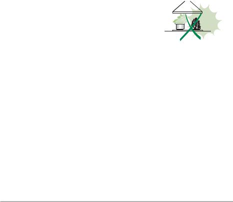
•Never leave high naked flames under the hood when it is in operation.
•Adjust the flame intensity to direct it onto the bottom of the pan only, making sure that it does not engulf the sides.
•Deep fat fryers must be continuously monitored
during use: overheated oil can burst into flames.
• Do not flambè under the range hood; risk of fire.
• This appliance can be used by children aged from 8 years and above and persons with reduced
physical, sensory or mental capabilities or lack of
experience and knowledge if they have been given supervision or instruction concerning use of the appliance in a safe way and understand the hazards involved. Children shall not play with the appliance. Cleaning and user maintenance shall not be made by children without supervision.
EN |
|
4 |
|
4 |

•“ CAUTION: Accessible parts may become hot when used with cooking appliances.”.
MAINTENANCE
•Switch off or unplug the appliance from the mains supply before carrying out any maintenance work.
•Clean and/or replace the Filters after the specified time period (Fire hazard).
•The Grease filters must be cleaned every 2 months of operation, or more frequently for particularly heavy usage, and can be washed in a dishwasher.
•The Activated charcoal filter is not washable and cannot be regenerated, and must be replaced approximately every 4 months of operation, or more frequently for particularly heavy usage.
•Clean the hood using a damp cloth and a neutral liquid detergent.
The symbol  on the product or on its packaging indicates that this product may not be treated as household waste. Instead it shall be handed over to the applicable collection point for the recycling of electrical and electronic equipment. By ensuring this product is disposed of correctly, you will help prevent potential negative consequences for the environment and human health, which could otherwise be caused by inappropriate waste handling of this product. For more detailed information about recycling of this product, please contact your local city office, your household waste disposal service or the shop where you purchased the product.
EN |
|
5 |
|
5 |

CHARACTERISTICS
Dimensions
* **
Min. Min. 550mm 550mm
*Dimensions of the hood in ducting version.
**Dimensions of the hood in recycling version.
EN |
|
6 |
|
6 |

Components
Ref. Q.ty Product Components
11 Hood Body, complete with: Controls, Light, Blower, Filters
2 |
1 |
Chimney Upper |
7.1 |
1 |
Telescopic frame complete with extractor, consisting of: |
7.1a |
1 |
Upper frame |
7.1b |
1 |
Lower frame |
9 |
1 |
Reducer Flange ø 150-120 mm |
10 |
1 |
Flange ø 120 mm |
15 |
1 |
Recirculation Air Outlet Connection |
25 |
|
Pipe clamps (not included) |
|
|
|
Ref. |
Q.ty |
Installation Components |
11 |
4 |
Wall Plugs ø 10 |
12c |
4 |
Screws 2,9 x 6,5 |
12f |
4 |
Screws M6 x 10 |
12g |
4 |
Screws M6 x 80 |
12h |
4 |
Screws 5,2 x 70 |
21 |
1 |
Drilling template |
22 |
4 |
6.4 mm int. dia washers |
23 |
4 |
M6 nuts |
|
|
|
|
Q.ty |
Documentation |
|
1 |
Instruction Manual |
21 |
|
|
|
|
|
|
12c |
|
|
23 |
|
22 |
|
11 |
15 |
|
|
|
|
|
12g |
12h |
|
|
|
|
|
|
|
|
10 |
7.1a |
|
|
|
|
|
|
25 |
7.1 |
|
9 |
|
7.1b |
|
|
|
|
|
2 |
|
|
1 |
|
|
|
12f |
|
|
EN |
|
7 |
|
7 |

INSTALLATION
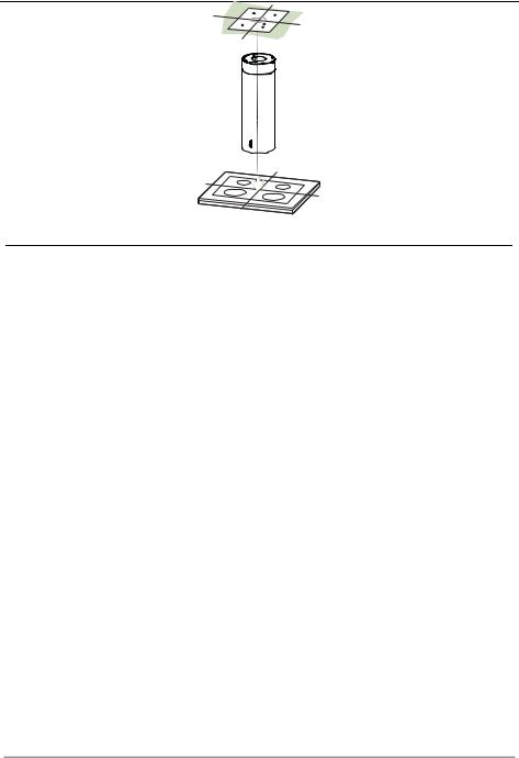
Drilling the Ceiling/shelf and fixing the frame
DRILLING THE CEILING/SHELF
•Use a plumb line to mark the centre of the hob on the ceiling/support shelf.
•Place the drilling template 21 provided on the ceiling/support shelf, making sure that the template is in the correct position by lining up the axes of the template with those of the hob.
•Mark the centres of the holes in the template.
•Drill the holes at the points marked:
•For concrete ceilings, drill for plugs appropriate to the screw size.
•For hollow brick ceilings with wall thickness of 20 mm: drill ø 10 mm(immediately insert the Dowels 11 supplied).
•For wooden beam ceilings, drill according to the wood screws used.
•For wooden shelf, drill ø 7 mm.
•For the power supply cable feed, drill ø 10 mm.
•For the air outlet (Ducted Version), drill according to the diameter of the external air exhaust duct connection.
•Insert two screws of the following type, crossing them and leaving 4-5 mm from the ceiling:
•For concrete ceilings, use the appropriate plugs for the screw size (not provided).
•for Cavity ceiling with inner space, with wall thickness of approx. 20 mm, Screws 12h, supplied.
•For wooden beam ceilings, use 4 wood screws (not provided).
•For wooden shelf, use 4 screws 12g with washers 22 and nuts 23, provided.
EN |
|
8 |
|
8 |

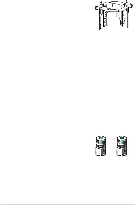
PREPARATION OF THE FRAME FOR THE HOOD IN RE-
CYCLING VERSION
In case the hood is used in recycling version it is necessary to prepare the frame with all the necessary connection pieces. In order to make the installation easier it is necessary to lengthen the frame:
•Unscrew the two screws 2.1 fixing the upper chimney to the frame and pull the chimney out.
•Unscrew the four safety screws placed at the top in the frame separation area. (A).
•Unscrew the eight metric screws connecting the two columns, placed on both sides of the frame (B).
A
B
Installation of components in recycling version: |
12c |
|
|
||
• |
Fix the recycling air outlet piece 15 to the upper part |
|
|
of the frame using four 12c screws supplied with the |
|
|
hood. |
|
• |
Fix the flange (ø120) 10 to the lower part of the recy- |
15 |
|
cling air outlet 15. |
|
|
|
|
• Put the reducer flange 9 on the hood body outlet. |
|
|
• |
At this point, join the flanges with a pipe. In order to |
|
|
calculate the height of the pipe it is necessary to es- |
10 |
|
timate the height of the hood (mm) and subtract 615 |
|
|
|
|
|
mm. (H pipe = H hood-615). |
|
•Lengthen the frame so that the pipe can be inserted. Place the pipe between the two flanges and block it. Make sure that the height of the frame is correct considering the height of the cooker hood (H frame = H hood – 184). Adjust the height of the frame and tighten again the earlier removed screws. Tighten again the safety screws in order to give more stability to the structure.
•Fix the pipe with the pipe clamps 25 supplied with the hood.
WARNING: For the Recirculation version only: remove the sticker from the slots on the upper chimney!
EN |
|
9 |
|
9 |
FIXING THE FRAME
•Lift the frame up, making sure that the index over the frame plate is turned forwards.
•Fit the frame slots onto the two screws inserted in the ceiling as above, and turn until reaching the centre of the adjustment slot.
•Tighten the two screws and fasten the other two screws provided; before locking the screws completely, it is possible to adjust the frame by turning it, making sure that the screws do not come out of their housing in the adjustment slot.
•The Frame must be securely fastened so as to support both the weight of the Hood and the stress caused by occasional axial pressure against the fitted Appliance. After fixing, make sure that the base is stable even when the Frame is subjected to lateral stress.
•If the Ceiling is not strong enough in the area where the hood is to be fixed, the Installer must strengthen the area using suitable plates and counterplates anchored to resistant structures.
1 |
1 |
2 |
2 |
|
|
Ducted version air exhaust system Connection
When installing the ducted version, connect the hood to the chimney using either a flexible or rigid pipe ø 150 or 120 mm, the choice of which is left to the installer.
•To install a ø 120 mm air exhaust connection, insert the reducer flange 9 on the hood body outlet.
•Fix the pipe using the pipe clamps 25 (not provided).
•Remove any activated charcoal filters.
|
9 |
ø 150 |
ø 120 |
EN |
|
1 |
|
10 |

Installing of the chimney and fixing of the hood
When the hood is installed in recycling version the chimney has to be positioned with the slots upwards. When the hood is installed in ducting version it has to be positioned in the opposite way.
•Place the chimney on the frame and fix it to the upper part of it with the earlier removed screws. When installing the hood in recycling version make sure that the slots correspond to the air outlet of the recycling air outlet piece 15.
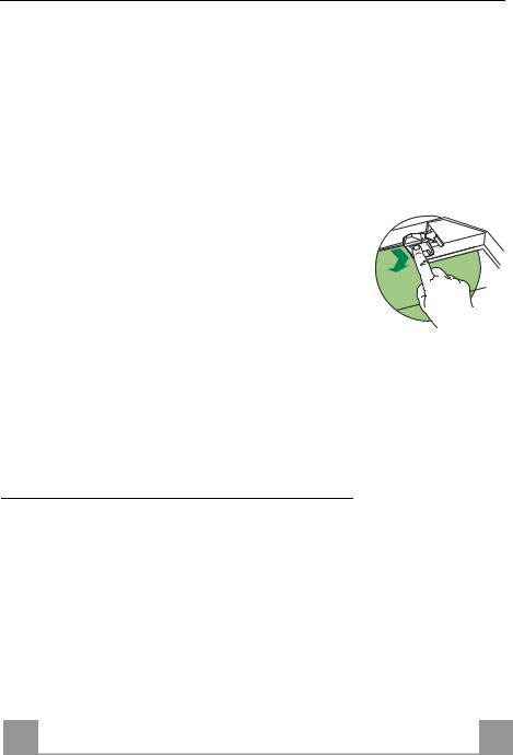
•Open the lighting unit by slightly pulling the notch. Remove the unit from the hood by sliding the fixing pivot.
•Remove the filter pushing it towards the back side of the hood unit and simultaneously pulling downwards.
•Remove possible charcoal filters.
•In order to fix the hood body to the frame insert the 4 screws 12f in their seats. It is necessary to leave at least 4-5 mm gap between the screw heads and the frame plate.
•Hook the hood canopy to the frame and turn it to the left until it reaches the stop, then lock the screws immediately to prevent the hood canopy from falling out accidentally.
1 |
2 |
Electrical connection
• Connect to hood to the mains supply through a double pole switch with at least 3 mm clearance between the contacts.
• Make sure that the connecting piece of the cable is correctly put in the socket.
•Connect the Cmd-connectors of the controls.
•Connect the Lux-connectors of the lighting system.
•In the recycling hood put the charcoal filter in its place.
• Put the metal grease filter and the confort panel into their proper seats.

 Cmd
Cmd
Lux
EN |
|
1 |
|
11 |

USE
A |
D |
B |
C |
E |
F |
G |
H |
Control panel
|
Button |
Function |
Display |
|
|
A |
Turns the suction motor on and off at speed one. |
Displays the set speed |
|
|
B |
Decreases the working speed. |
Displays the set speed |
|
|
C |
Increases the working speed. |
Displays the set speed |
|
|
D |
Activate intensive speed from any other speed, |
Displays HI and the time remaining once very second. |
|
|
|
including motor off. This speed is set to operate |
|
|
|
|
for 6 minutes, after which the system returns to the |
|
|
|
|
speed that was set before. Suitable to deal with |
|
|
|
|
maximum levels of cooking fumes. |
|
|
|
|
Press and hold the button for approximately 5 |
FC+Punto (2 flashes)–Alarm On. |
|
|
|
seconds, with all the loads turned off (Motor and |
FC+Punto (1 flash)–Alarm Off. |
|
|
|
Lights), to turn the Activated Charcoal Filter |
|
|
|
|
alarm On and Off. |
|
|
|
E |
24H function |
Displays 24 and the spot at the bottom right flashes once |
|
|
|
Turns the suction motor on at speed one and |
every second, while the motor is running. |
|
|
|
effects one 10 minute extraction every hour. |
It is disabled by pressing the button. |
|
|
|
When the filters alarm is triggered, the alarm can |
FF flashes three times. |
|
|
|
be reset by pressing and holding this button for |
|
|
|
|
approximately 3 seconds. |
When the procedure terminates, the indication shown |
|
|
|
These indications are only visible when the motor |
previously turns off: |
|
|
|
is turned off. |
FG indicates the need to wash the metal grease filters. |
|
|
|
|
The alarm is triggered after the Hood has been in |
|
|
|
|
operation for 100 working hours. |
|
|
|
|
FC indicates the need to change the activated charcoal |
|
|
|
|
filters, and also to wash the metal grease filters. The alarm |
|
|
|
|
is triggered after the Hood has been in operation for 200 |
|
|
|
|
working hours. |
|
|
F |
Delay function |
Displays the operating speed and the spot at the bottom |
|
|
|
Activate automatic switch-off with a 30’ delay. |
right flashes once a second. |
|
|
|
Suitable to complete elimination of residual |
|
|
|
|
odours. Can be activated from any position, and is |
|
|
|
|
disabled by pressing the button or turning the |
|
|
|
|
motor off. |
|
|
|
|
Press and hold the button for approximately 5 |
IR+Punto (2 flashes)–Alarm On. |
|
|
|
seconds, with all the loads turned off (Motor and |
IR+Punto (1 flash)–Alarm Off. |
|
|
|
Lights), to turn the Remote Control On and Off. |
|
|
|
G |
Turns the lighting system on and off at maximum |
|
|
|
|
intensity. |
|
|
|
H |
Turns the Courtesy Lighting on and off. |
|
|
|
|
|
|
|
EN |
|
1 |
|
12 |

MAINTENANCE
REMOTE CONTROL (OPTIONAL)
The appliance can be controlled using a remote control powered by a 1.5 V carbon-zinc alkaline batteries of the standard LR03AAA type (not included).
•Do not place the remote control near to heat sources.
•Used batteries must be disposed of in the proper manner.
Cleaning the Comfort Panels
•Pull the Comfort Panel to open it.
•Disconnect the panel from the hood canopy by sliding the fixing pin lever.
•The comfort panel must never be washed in a dishwasher.
•Clean the outside by using a damp cloth and neutral liquid detergent.
•Clean the inside as well by using a damp cloth and neutral detergent; do not use wet cloths or sponges, or jets of water; do not use abrasive substances.
•When the above operation has been completed, hook the panel back to the hood canopy and close it by turning the knob in the opposite direction.
Metal grease filters
They can be washed in the dishwasher, and need to be cleaned whenever the FG sign appears on the display or at least once every 2 months use, or more frequently if use is particularly intensive.
Resetting the alarm signal
•Turn the Lights and the Suction motor off, then disable the 24h function, if enabled.
•Press button E (see the paragraph on Use).
Cleaning the Filters
•Open the lighting unit by pulling on the nocth.
•Remove the Filters one at a time, pushing them towards the back of the unit and at the same time pulling downward.
•Wash the Filters without bending them, and leave them to dry completely before replacing. (If the surface of the filter changes colour as time goes by, this will have absolutely no effect on the efficiency of the filter itself.)
•Replace, taking care to ensure that the handle faces forwards.
•Replace the lighting unit.
EN
1
13
Activated Charcoal Filter (Recirculation Version)
It cannot be washed or regenerated, and must be changed when the FC symbol on the display appears, or at least once every 4 months. The Alarm signal, if it has been activated, only appears when the Suction motor is turned on.
Activating the alarm signal
•In Recirculation Version Hoods, the Filter Saturation Alarm must be activated on installation or at a later date.
•Turn the Lights and the Suction Motor off.
•Press D and hold for approximately 5 Seconds:
•The message FC+Puntino flashes twice, A.C. Filter saturation alarm ACTIVATED
•The message FC+Puntino flashes once, A.C. Filter saturation alarm DEACTIVATED
CHANGING THE ACTIVATED CHARCOAL FILTER
Resetting the alarm signal
• Turn the Lights and the Suction motor off, then disable the 24h function, if enabled.
• Press button E (see paragraph on Use).
Changing the Filter
• Open the lighting unit by pulling on the notch provided.
•Remove the Metal grease filters.
•Remove the saturated Activated charcoal filter, using the hooks provided.
•Fit the new Filter, hooking it into place.
•Replace the Metal grease filters.
•Close the lighting unit again.
Lighting unit
Warning: This appliance is fitted with a white LED lamp classed as 1M according to EN 60825-1: 1994 + A1:2002 + A2:2001 standards; maximum optical power emitted @439nm: 7µW. Do not look directly at the light through optical devices (binoculars, magnifying glasses…).
•For replacement contact technical support. ("To purchase contact technical support")
EN
1
14

CONSIGLI E SUGGERIMENTI
 Le Istruzioni per l’uso si riferiscono ai diversi modelli di questo apparecchio. Pertanto, si potrebbero trovare descrizioni di singole caratteristiche che non appartengono al proprio apparecchio specifico.
INSTALLAZIONE
•Il fabbricante non potrà ritenersi responsabile per eventuali danni risultanti da un’installazione o utilizzazione impropria.
•La distanza minima di sicurezza tra il piano cottura e la cappa aspirante è di 650 mm (alcuni modelli
possono essere installati a un’altezza inferiore; vedere il paragrafo relativo alle dimensioni di lavoro e all'installazione).
• Controllare che la tensione di rete corrisponda a quella indicata sulla targa dati applicata all’interno della cappa.
• |
Per gli apparecchi di Classe I, controllare che la rete di alimentazione |
|
||||
|
domestica disponga di un adeguato collegamento a massa. |
|
||||
|
Collegare l'aspiratore al condotto dei fumi mediante un tubo con diametro |
|
||||
|
minimo di 120 mm. Il percorso dei fumi deve essere il più corto possibile. |
|
||||
• |
Non collegare la cappa aspirante ai condotti fumari che trasportano fumi di |
|
||||
|
combustione (per es. caldaie, camini ecc.). |
|
||||
• |
Se l’aspiratore è utilizzato in combinazione con |
2° |
||||
|
apparecchi non elettrici (per es. apparecchi a gas), |
|||||
|
|
|||||
|
deve essere garantito un sufficiente grado di |
|
|
|
||
|
|
|
|
|||
|
|
|
|
|
||
|
aerazione nel locale per impedire il ritorno di flusso |
|
|
|
||
|
dei gas di scarico. La cucina deve avere un'apertura |
|
|
|
||
|
comunicante direttamente con l'esterno per garantire |
|
|
|
|
|
|
|
|
|
|
|
|
|
|
|
|
|
|
|
|
l'afflusso di aria pulita. Quando la cappa per cucina è utilizzata in |
|
||||
|
combinazione con apparecchi non alimentati dalla corrente elettrica, la |
|
||||
|
pressione negativa nel locale non deve superare 0,04 mbar per evitare che i |
|||||
|
fumi vengano riaspirati nel locale dalla cappa. |
|
||||
•In caso di danneggiamento del cavo di alimentazione, occorre farlo sostituire dal produttore o dal reparto di assistenza tecnica per evitare qualsiasi rischio.
IT |
|
1 |
|
15 |
•Se le istruzioni di installazione del piano cottura a gas specificano una distanza maggiore di quella sopra indicata, è necessario tenerne conto. Devono essere rispettate tutte le normative riguardanti lo scarico dell'aria.
•Usare solo viti e minuteria di tipo idoneo per la cappa.
Avvertenza: la mancata installazione delle viti o dei dispositivi di fissaggio in conformità alle presenti istruzioni può comportare rischi di scosse elettriche.
•Collegare la cappa all'alimentazione di rete mediante un interruttore bipolare con distanza tra i contatti di almeno 3 mm.
USO
•La cappa aspirante è progettata esclusivamente per l’uso domestico allo scopo di eliminare gli odori dalla cucina.
•Non usare mai la cappa per scopi diversi da quelli per cui è stata progettata.
•Non lasciare mai fiamme alte sotto la cappa quando è in funzione.
•Regolare l'intensità della fiamma in modo da dirigerla esclusivamente verso il fondo del recipiente di cottura, assicurandosi che non ne avvolga i lati.
•Le friggitrici devono essere costantemente
controllate durante l’uso: l’olio surriscaldato potrebbe incendiarsi.
• Non cuocere al flambé sotto la cappa: si potrebbe sviluppare un incendio.
•Questo apparecchio può essere utilizzato da
bambini di età non inferiore a 8 anni e da persone con ridotte capacità psico- fisico-sensoriali o con esperienza e conoscenze insufficienti, purché attentamente sorvegliati e istruiti su come utilizzare in modo sicuro l'apparecchio e sui pericoli che ciò comporta. Assicurarsi che i bambini non giochino con l'apparecchio. Pulizia e manutenzione da parte dell'utente non devono essere effettuate da bambini, a meno che non siano sorvegliati.
IT |
|
1 |
|
16 |

•“ ATTENZIONE: le parti accessibili possono diventare molto calde durante l’uso degli apparecchi di cottura ”.
MANUTENZIONE
•Spegnere o scollegare l’apparecchio dalla rete di alimentazione prima di qualunque operazione di pulizia o manutenzione.
•Pulire e/o sostituire i filtri dopo il periodo di tempo specificato (pericolo di incendio).
•I filtri antigrasso devono essere puliti ogni 2 mesi di funzionamento o più frequentemente in caso di utilizzo molto intenso e possono essere lavati in lavastoviglie.
•Il filtro al carbone attivo non è lavabile né è rigenerabile e deve essere sostituito ogni 4 mesi di funzionamento circa o più frequentemente in caso di utilizzo molto intenso.
•Pulire la cappa utilizzando un panno umido e un detergente liquido neutro.
Il simbolo  sul prodotto o sulla sua confezione indica che il prodotto non può essere smaltito come un normale rifiuto domestico. Il prodotto da smaltire deve essere conferito presso un apposito centro di raccolta per il riciclaggio dei componenti elettrici ed elettronici. Assicurandosi che questo prodotto sia smaltito correttamente, si contribuirà a prevenire potenziali conseguenze negative per l’ambiente e per la salute che potrebbero altrimenti derivare dal suo smaltimento inadeguato. Per informazioni più dettagliate sul riciclaggio di questo prodotto, contattare il Comune, il servizio locale di smaltimento rifiuti oppure il negozio dove è stato acquistato il prodotto.
IT |
|
1 |
|
17 |

CARATTERISTICHE
Ingombro
* **
Min. Min. 550mm 550mm
*Dimensioni per cappa in versione aspirante.
**Dimensioni per cappa in versione filtrante.
IT |
|
1 |
|
18 |

Componenti
Rif. Q.tà Componenti di Prodotto
11 Corpo Cappa completo di: Comandi, Luce, Filtri, Camino Inferiore
2 |
1 |
Camino superiore |
7.1 |
1 |
Traliccio telescopico completo di Aspiratore,formato da: |
7.1a |
1 |
Traliccio superiore |
7.1b |
1 |
Traliccio inferiore |
9 |
1 |
Flangia di riduzione ø 150-120 mm |
10 |
1 |
Flangia ø 120 mm |
15 |
1 |
Raccordo Uscita Aria Filtrante |
25 |
|
Fascette stringitubo (non incluse) |
|
|
|
Rif. |
Q.tà |
Componenti di Installazione |
11 |
4 |
Tasselli ø 10 |
12c |
4 |
Viti 2,9 x 6,5 |
12f |
4 |
Viti M6 x 15 |
12g |
4 |
Viti M6 x 80 |
12h |
4 |
Viti 5,2 x 70 |
21 |
1 |
Dima di foratura |
22 |
4 |
Rondelle ø 6,4 |
23 |
4 |
Dadi M6 |
|
|
|
|
Q.tà |
Documentazione |
|
1 |
Libretto Istruzioni |
21 |
|
|
|
|
|
|
12c |
|
|
23 |
|
22 |
|
11 |
15 |
|
|
|
|
|
12g |
12h |
|
|
|
|
|
|
|
|
10 |
7.1a |
|
|
|
|
|
|
25 |
7.1 |
|
9 |
|
7.1b |
|
|
|
|
|
2 |
|
|
1 |
|
|
|
12f |
|
|
IT |
|
1 |
|
19 |
INSTALLAZIONE
Foratura Soffitto/Mensola e Fissaggio Traliccio
FORATURA SOFFITTO/MENSOLA
•Con l’ausilio di un Filo a piombo riportare sul Soffitto/Mensola di supporto il centro del Piano di Cottura.
•Appoggiare al Soffitto/Mensola la Dima di Foratura 21 in dotazione, facendo coincidere il suo centro al centro proiettato e allineando gli assi della Dima agli assi del Piano di Cottura.
•Segnare i centri dei Fori della Dima.
•Forare i punti seguenti:
•Soffitto in Calcestruzzo massiccio: secondo Tasselli per Calcestruzzo impiegati.
•Soffitto in Laterizio a camera d’aria, con spessore resistente di 20 mm: ø 10 mm (inserire subito i Tasselli 11 in dotazione).
•Soffitto in Travatura di Legno: secondo Viti per Legno impiegate.
•Mensola in Legno: ø 7 mm.
•Passaggio del Cavo elettrico di Alimentazione: ø 10 mm.
•Uscita Aria (Versione Aspirante): secondo diametro del collegamento alla Tubazione di Evacuazione Esterna.
•Avvitare, incrociandole e lasciando 4-5 mm dal soffitto, due viti:
•per Calcestruzzo massiccio, Tasselli per Calcestruzzo, non in dotazione.
•per Laterizio a camera d’aria, con spessore resistente di 20 mm circa, Viti 12h, in dotazione.
•per Travatura di legno, Viti per legno, non in dotazione.
•per Mensola in Legno, viti 12g con Rondelle 22 e Dadi 23, in dotazione.
IT |
|
2 |
|
20 |
PREPARAZIONE DEL TRALICCIO PER LA CONNESIONE |
A |
|
|
FILTRANTE |
|
Nel caso in cui si installi la cappa in versione filtrante |
|
|
bisogna predisporre nel traliccio tutti i raccordi necessa- |
B |
|
ri per tale versione. Per facilitare l’installazione dei par- |
|
|
ticolari per la versione filtrante è necessario allungare il |
|
|
traliccio, procedere come segue: |
|
|
• |
Svitare le due viti che fissano il camino superiore 2.1 |
|
|
al traliccio e sfilare il camino. |
|
• |
Svitare le quattro viti di sicurezza poste in alto nella |
|
|
zona di separazione del traliccio. (A) |
|
• |
Svitare le otto viti metriche che uniscono le due co- |
|
|
lonne, poste ai lati del traliccio. (B) |
12c |
Installazione dei componenti per versione filtrante: |
|
|
• Fissare il raccordo filtrante 15 alla parte superiore del |
|
|
|
traliccio utilizzando le 4 viti 12c in dotazione. |
|
• |
Agganciare con movimento rotativo la flangia (ø120) |
15 |
|
10 alla parte inferiore del raccordo filtrante 15. |
|
|
|
|
• |
Inserire la flangia di riduzione 9 sull’uscita dell’aspi- |
|
|
ratore. |
|
• |
A questo punto bisogna collegare le due flangie con |
10 |
|
un tubo, per calcolare l’altezza del tubo occorre sti- |
|
|
|
|
|
mare l’altezza della cappa (mm) e sottrarre 615 mm. |
|
|
(H tubo = H cappa-615). |
|
•Allungare il traliccio tanto da permettere l’inserimento del tubo e riposizionarlo bloccando il tubo tra le due flangie. Verificare se l’altezza del traliccio è adeguata all’altezza desiderata della cappa (H traliccio = H cappa – 184). Regolare l’altezza desiderata del traliccio e riavvitare le viti precedentemente tolte. Per garantire una maggiore stabilità al traliccio riavvitare le quattro viti di sicurezza sull’ultimo foro disponibile.
•Fissare il tubo con le fascette stringitubo 25 in dotazione.
ATTENZIONE: Solo per la Versione filtrante rimuovere l’etichetta adesiva dalle asole sul camino superiore!
IT |
|
2 |
|
21 |

FISSAGGIO TRALICCIO
•Sollevare il traliccio facendo attenzione che l’indice posto sopra la piastra del traliccio sia nella parte anteriore.
•Incastrare le asole del traliccio sulle due viti predisposte precedentemente al soffitto e ruotare fino al centro dell’asola di regolazione.
•Stringere le due viti e avvitare le altre due in dotazione; prima di serrare definitivamente le viti è possibile effettuare delle regolazioni ruotando il traliccio, facendo attenzione che le viti non escano dalla sede dell’asola di regolazione.
•Il fissaggio del Traliccio deve essere sicuro in relazione sia al peso della Cappa sia alle sollecitazioni causate da occasionali spinte laterali all’Apparecchio montato. A fissaggio avvenuto verificare quindi che la base sia stabile anche se il Traliccio è sollecitato a flessione.
•In tutti i casi in cui il Soffitto non fosse sufficientemente robusto sul punto di sospensione, l’Installatore dovrà provvedere a irrobustirlo con opportune piastre e contropiastre ancorate a parti strutturalmente resistenti.
1 |
1 |
2 |
2 |
|
|
Connessione Uscita aria Versione Aspirante
Per installazione in Versione Aspirante collegare la Cappa alla tubazione di uscita per mezzo di un tubo rigido o flessibile di ø 150 o 120 mm, la cui scelta è lasciata all’installatore.
•Per collegamento con tubo ø 120 mm, inserire la Flangia di riduzione 9 sull’Uscita del Corpo Cappa.
•Fissare il tubo con adeguate fascette stringitubo 25(non incluse).
•Rimuovere eventuali filtri al carbone attivo.
|
9 |
ø 150 |
ø 120 |
IT |
|
2 |
|
22 |

Montaggio Camino e Fissaggio Corpo Cappa
Il camino va girato con le asole verso l’alto in caso di installazione della cappa in versione filtrante, viceversa con le asole verso il basso in caso di installazione in versione aspirante.
•Infilare dal basso verso l’alto il Camino superiore e fissarlo nella parte superiore al Traliccio con 2 Viti tolte in precedenza, prestando attenzione nel caso di installazione filtrante che le asole del camino sia in corrispondenza dell’uscita del raccordo filtrante 15.
•Aprire il gruppo illuminazione tirandolo sull’apposita intacca, sganciarlo dal corpo cappa facendo scorrere l’apposito perno di fissaggio.
•Togliere il Filtro Antigrasso, spingendolo verso la parte posteriore del gruppo e tirando contemporaneamente verso il basso.
•Togliere eventuali Filtri Antiodore al Carbone attivo.
•Predisporre il fissaggio del corpo cappa al traliccio avvitando le 4 Viti 12f nelle apposite sedi.Lasciare almeno 4-5 mm di spazio tra la testa della vite e la piastra del traliccio.
•Agganciare il corpo cappa al traliccio e ruotare verso sinistra fino alla battuta, procedere immediatamente al bloccaggio delle viti così da evitare un’accidentale caduta del corpo cappa.
1 |
2 |
Connessione elettrica
• Collegare la Cappa all’Alimentazione di Rete interponendo un Interruttore bipolare con apertura dei contatti di almeno 3 mm.
• Assicurarsi che il connettore del Cavo di alimentazione sia correttamente inserito nella presa dell’Aspiratore
•Collegare i connettori dei Comandi Cmd.
•Collegare i connettori dei Faretti Lux.
•Per la Versione Filtrante montare il Filtro Antiodore al Carbo-
ne attivo.
• Rimontare il Filtro Antigrasso e successivamente il pannello aspirante.

 Cmd
Cmd
Lux
IT |
|
2 |
|
23 |
 Loading...