


GB
IT
FR
DE
TR
Instructions for use and installation
Cooker Hood
Istruzioni per l’uso e l’installazione
Cappa
Mode d’emploi et installation
Hotte de Cuisine
Bedienungsanleitung und Einrichtung
Dunstabzugshaube
Kullanım ve montaj talimatları
Davlumbaz
FAK 907 I

Instructions Manual |
|
INDEX |
|
RECOMMENDATIONS AND SUGGESTIONS |
......................................................................................................................7 |
CHARACTERISTICS.............................................................................................................................................................. |
8 |
INSTALLATION .................................................................................................................................................................... |
10 |
USE....................................................................................................................................................................................... |
14 |
MAINTENANCE.................................................................................................................................................................... |
15 |
EN |
|
2 |
|
2 |

Libretto di Istruzioni |
|
INDICE |
|
CONSIGLI E SUGGERIMENTI ............................................................................................................................................ |
17 |
CARATTERISTICHE ............................................................................................................................................................ |
18 |
INSTALLAZIONE.................................................................................................................................................................. |
20 |
USO ...................................................................................................................................................................................... |
24 |
MANUTENZIONE ................................................................................................................................................................. |
25 |
IT |
|
3 |
|
3 |

Manuel d’Instructions |
|
SOMMAIRE |
|
CONSEILS ET SUGGESTIONS .......................................................................................................................................... |
27 |
CARACTERISTIQUES ......................................................................................................................................................... |
28 |
INSTALLATION .................................................................................................................................................................... |
30 |
UTILISATION........................................................................................................................................................................ |
34 |
ENTRETIEN.......................................................................................................................................................................... |
35 |
FR |
|
4 |
|
4 |

Bedienungsanleitung |
|
INHALTSVERZEICHNIS |
|
EMPFEHLUNGEN UND HINWEISE.................................................................................................................................... |
37 |
CHARAKTERISTIKEN.......................................................................................................................................................... |
38 |
MONTAGE............................................................................................................................................................................ |
40 |
BEDIENUNG......................................................................................................................................................................... |
44 |
WARTUNG............................................................................................................................................................................ |
45 |
DE |
|
5 |
|
5 |

Kullanim Kilavuku |
|
IÇERIKLER |
|
TAVSIYELER VE ÖNERILER .............................................................................................................................................. |
47 |
ÖZELLIKLER ........................................................................................................................................................................ |
48 |
MONTAJ ............................................................................................................................................................................... |
50 |
KULLANIM ............................................................................................................................................................................ |
54 |
BAKIM................................................................................................................................................................................... |
55 |
TR |
|
6 |
|
6 |
RECOMMENDATIONS AND SUGGESTIONS
 The Instructions for Use apply to several versions of this appliance. Accordingly, you may find descriptions of individual features that do not apply to your specific appliance.
INSTALLATION
•The manufacturer will not be held liable for any damages resulting from incorrect or improper installation.
•The minimum safety distance between the cooker top and the extractor hood is 500 mm.
•Check that the mains voltage corresponds to that indicated on the rating plate fixed to the inside of the hood.
•For Class I appliances, check that the domestic power supply guarantees adequate earthing.
Connect the extractor to the exhaust flue through a pipe of minimum diameter 120 mm. The route of the flue must be as short as possible.
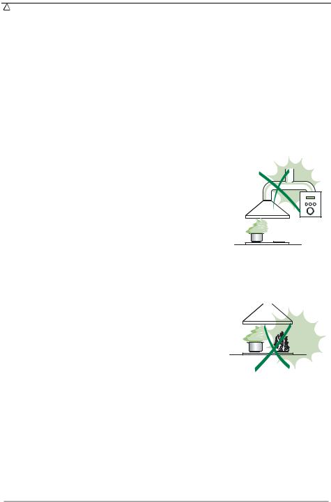
•Do not connect the extractor hood to exhaust ducts carrying combustion fumes (boilers, fireplaces, etc.).
•If the extractor is used in conjunction with non-electrical appliances (e.g. gas burning appliances), a sufficient degree of aeration must be guaranteed in the room in order to prevent the backflow of exhaust gas. The kitchen must have an opening communicating directly with the open air in order to guarantee the entry of clean air.
USE
• The extractor hood has been designed exclusively for domestic use to eliminate kitchen smells.
• Never use the hood for purposes other than for which it has ben designed.
• Never leave high naked flames under the hood when it is in operation.
•Adjust the flame intensity to direct it onto the bottom of the pan only, making sure that it does not engulf the sides.
•Deep fat fryers must be continuously monitored during use: overheated oil can burst into flames.
•Do not flambè under the range hood; risk of fire
•This appliance is not intended for use by persons (including children) with reduced physical, sensory or mental capabilities, or lack of experience and knowledge, unless they have been given supervision or instruction concerning use of the appliance by a person responsible for their safety.
• Children should be supervised to ensure that they do not play with the appliance.
MAINTENANCE
•Switch off or unplug the appliance from the mains supply before carrying out any maintenance work.
•Clean and/or replace the Filters after the specified time period.
•Clean the hood using a damp cloth and a neutral liquid detergent.
EN |
|
7 |
|
7 |

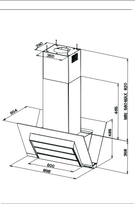
CHARACTERISTICS
Dimensions
EN |
|
8 |
|
8 |
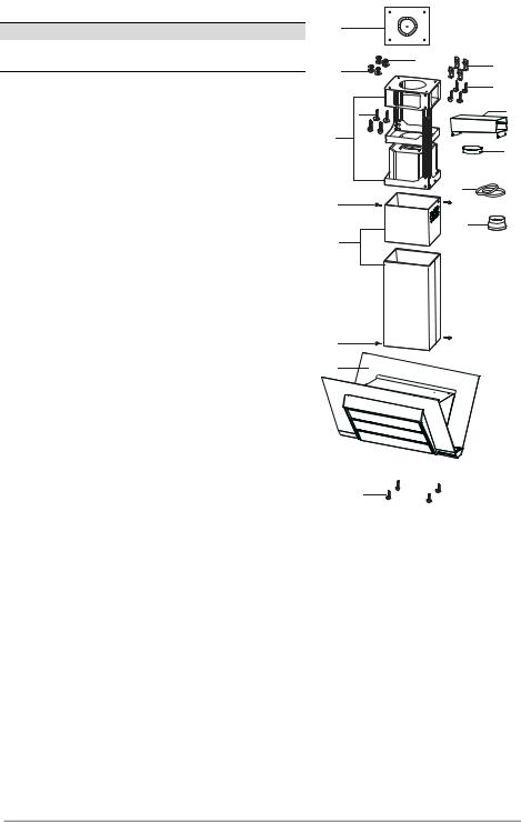
Components
Ref. Q.ty Product Components
11 Hood Body, complete with: Controls, Light, Blower, Filters
2 |
1 |
Telescopic Chimney comprising: |
2.1 |
1 |
Upper Section |
2.2 |
1 |
Lower Section |
7.1 |
1 |
Telescopic frame complete with extractor, consisting of: |
7.1a |
1 |
Upper frame |
7.1b |
1 |
Lower frame |
9 |
1 |
Reducer Flange ø 150-120 mm |
10 |
1 |
Flange ø 150 |
15 |
1 |
Air Outlet Connection |
25 |
2 |
Pipe clamps |
Ref. |
Q.ty |
Installation Components |
11 |
4 |
Wall Plugs ø 10 |
12c |
6 |
Screws 2,9 x 6,5 |
12f |
4 |
Screws M6 x 10 |
12g |
4 |
Screws M6 x 80 |
12h |
4 |
Screws 5,2 x 70 |
21 |
1 |
Drilling template |
22 |
4 |
6.4 mm int. dia washers |
23 |
4 |
M6 nuts |
|
Q.ty |
Documentation |
|
1 |
Instruction Manual |
21 |
|
|
|
23 |
11 |
22 |
|
|
|
|
|
7.1a |
|
12h |
|
|
|
12g |
|
15 |
7.1 |
|
|
|
|
10 |
7.1b |
|
|
|
|
25 |
12c |
|
|
2.1 |
|
9 |
|
|
|
2 |
|
|
2.2 |
|
|
12c |
|
|
1 |
|
|
12f |
|
|
EN |
|
9 |
|
9 |

INSTALLATION
Drilling the Ceiling/shelf and fixing the frame
DRILLING THE CEILING/SHELF
•Use a plumb line to mark the centre of the hob on the ceiling/support shelf.
•Place the drilling template 21 provided on the ceiling/support shelf, making sure that the template is in the correct position by lining up the axes of the template with those of the hob.
•Mark the centres of the holes in the template.
•Drill the holes at the points marked:
•For concrete ceilings, drill for plugs appropriate to the screw size.
•For hollow brick ceilings with wall thickness of 20 mm: drill ø 10 mm(immediately insert the Dowels 11 supplied).
•For wooden beam ceilings, drill according to the wood screws used.
•For wooden shelf, drill ø 7 mm.
•For the power supply cable feed, drill ø 10 mm.
•For the air outlet (Ducted Version), drill according to the diameter of the external air exhaust duct connection.
•Insert two screws of the following type, crossing them and leaving 4-5 mm from the ceiling:
•For concrete ceilings, use the appropriate plugs for the screw size (not provided).
•for Cavity ceiling with inner space, with wall thickness of approx. 20 mm, Screws 12h, supplied.
•For wooden beam ceilings, use 4 wood screws (not provided).
•For wooden shelf, use 4 screws 12g with washers 22 and nuts 23, provided.
EN |
|
1 |
|
10 |
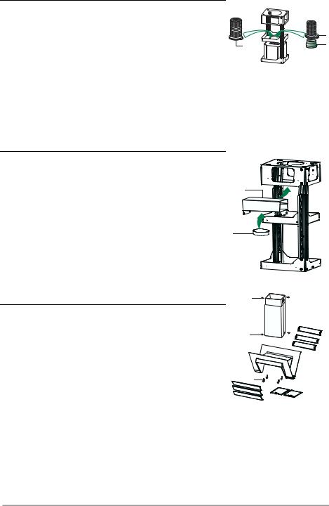
Fixing the frame
• Loosen the two screws fastening the lower chimney and remove this from the lower frame.
• Loosen the two screws fastening the upper chimney and remove this from the upper frame.
If you wish to adjust the height of the frame, proceed as |
|
|
|
follows: |
|
|
|
• |
Unfasten the eight metric screws joining the two col- |
|
|
|
umns, located at the sides of the frame. |
|
|
• |
Adjust the frame to the height required, then replace |
|
|
|
all the screws removed as above. |
|
|
• Insert the upper chimney stack from above, and leave |
|
|
|
|
it running free on the frame. |
1 |
1 |
|
|
||
•Lift up the frame, fit the frame slots onto the screws up to the slot end positions.
• Tighten the two screws and fasten the other two screws provided with the hood.
Before tightening the screws completely it is possible to |
2 |
2 |
adjust the frame by turning it. Make sure that the screws do not come out of their seats in the slotted holes.
•The frame mountings must be secure to withstand the weight of the hood and any stresses caused by the occasional side thrust applied to the device.
On completion, check that the base is stable, even if the frame is subjected to bending.
•In all cases where the ceiling is not strong enough at the suspension point, the installer must provide strengthening using suitable plates and backing pieces anchored to the structurally sound parts.
EN |
|
1 |
|
11 |
Connections
DUCTED VERSION AIR EXHAUST SYSTEM
When installing the ducted version, connect the hood to the chimney using either a flexible or rigid pipe ø 150 or 120 mm, the choice of which is left to the installer.
•To install a ø 120 mm air exhaust connection, insert the reducer flange 9 on the hood body outlet.
•Fix the pipe in position using sufficient pipe clamps (not supplied).
•Remove any activated charcoal filters.
Recirculation version air outlet
•Fix the connection 15 to the frame using the 4 screws provided.
•Fix the flange 10 to the lower opening of the connection 15.
•Connect the hood air outlet to the flange in the lower part of the junction using a rigid or flexible ø 150 tube (by installer’s choice).
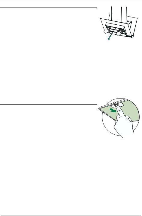
Fitting the Chimney and Fixing the Hood Canopy
•Position the upper chimney and fix the top part to the frame using the 2 screws 12c (2.9 x 6.5) supplied.
•Similarly, position the lower chimney and fix the bottom part to the frame using the 2 screws 12c (2.9 x 6.5) supplied.
Before fixing the hood canopy to the frame:
•Unfasten the panels from the hood canopy by pulling them.
•Remove the metal grease filters from the hood canopy.
•Remove any activated charcoal odour filters.
•Fix the hood canopy to the frame provided, working from below and using the 4 screws 12f (M6 x 10) supplied.
ø 150
25
15
10
12c
12c
12f
ø 120
25
9
EN |
|
1 |
|
12 |

ELECTRICAL CONNECTION
•Connect the Hood to the mains power supply, inserting a two-pole cut-out switch with contact aperture of at least 3 mm along the line.
•Pull the Comfort Panel to open it, ensure that the supply cable connector is properly inserted into the Suction device socket
•Join the connectors.
•Install the odour filter and the charcoal filter in case the hood is to be used in recycling version.
•Install the grease filter again, and successively the suction panel.
EN |
|
1 |
|
13 |
USE
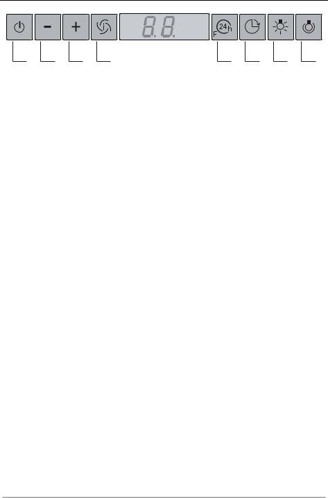
A B C D E F G H
Control board
Key |
Function |
Display |
|
|
|
A |
Switches the extractor motor on and off at the |
Indicates the selected speed. |
|
latest selected speed |
|
B |
Decreases the suction speed. |
|
|
|
|
C |
Increases the suction speed. |
|
|
|
|
D |
By pressing this key it is possible to activate |
HI appears. The spot down on the right side |
|
the intensive speed from any previously se- |
flashes once a second. |
|
lected speed. The intensive speed can be acti- |
|
|
vated even when the motor is OFF. This speed |
|
|
has been timed at 10 minutes. After that time |
|
|
the system activates automatically the latest |
|
|
selected speed. This function is suitable for |
|
|
cooking conditions when vapours and smells |
|
|
are of the utmost emission. |
|
E |
By pressing this key it is possible to set up the |
Indicates the 24-function. The spot down on |
|
motor to a suction speed at 100 m3/h lasting 10 |
the right side flashes and the motor is on. |
|
minutes every hour. After this the motor |
Once the process is finished the previous indi- |
|
switches off automatically. |
|
|
cation disappears: |
|
|
When the filter saturation is going on it is pos- |
|
|
FF Indicates that the metal grease filters |
|
|
sible to reset the alarm by pressing this key for |
saturation alarm has been triggered, and |
|
about 3 seconds. The indication is visible only |
|
|
the filters need to be washed. The alarm |
|
|
when the motor is off. |
is triggered after 100 working hours. |
|
|
EF Indicates that the charcoal filter satura- |
|
|
tion alarm has been triggered, and the fil- |
|
|
ter has to be replaced; the metal grease |
|
|
filters must also be washed. The charcoal |
|
|
filter is triggered after 200 working hours. |
F |
By pressing this key it is possible to set the |
Indicates alternately the selected speed of the |
|
delayed shutdown of the appliance to 30 min- |
hood and the time left before the hood shut- |
|
utes. This function is suitable for a complete |
down. The spot down on the right side flashes. |
|
elimination of the residual smells. It can be |
|
|
activated at any position, and it is deactivated |
|
|
by pressing the key again or by switching off |
|
|
the motor. |
|
G |
Turns light on and off . |
|
|
|
|
H |
Turns light on and off at reduced intensity. |
|
EN |
|
1 |
|
14 |
MAINTENANCE
Cleaning the Comfort Panel
•Remove the Comfort Panel by pulling it.
•The Comfort Panel must never be washed in the dishwasher.
•Clean the outside with a damp cloth an neutral liquid detergent.
• Clean the inside using a damp cloth and neutral detergent; do not use wet cloths or sponges, or jets of water; do not use abrasive substances.
• On completing the operation, hook the panel back onto the hood canopy.
Metal grease filters
Filters can be washed in the dish machine. They need to be  washed when FF-sign appears on the display or in any case every
2 months, or even more frequently in case of particularly intensive use of the hood.
Alarm reset
•Switch off the hood and the lights. If the 24h-function has been activated this has to be deactivated.
•Press the E-key till the display is unlit.
Cleaning the filters
•Pull the comfort panels to open them.
•Remove the filters one by one pushing them towards the back side of the hood unit and simultaneously pulling downwards.
•Any kind of bending of the filters has to be avoided when washing them. Before fitting them again into the hood make sure that they are completely dry. (The colour of the filter surface may change throughout the time but this has no influence to the filter efficiency).
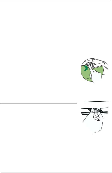
•When fitting the filters into the hood pay attention that they are mounted in correct position the handle facing outwards.
•Close the comfort panel.
EN |
|
1 |
|
15 |
Charcoal filter (recycling version)
•This filter cannot be washed or regenerated. It must be replaced when the EF appears on the display or at least once every 4 months.
Activation of the alarm signal
•In the recycling version hoods the filter saturation alarm must be activated during the installation or later.
•Switch off the hood and the lights.
•Disconnect the hood from the mains supply.
•When restoring the connection press and hold B-key.
•When releasing the key two rotating rectangles appear on the display.
•Within 3 seconds press the B-key until a flashing confirmation appears on the dispaly:
•2 flashes with EF - charcoal filter saturation alarm ACTIVATED
•1 flash with EF - charcoal filter saturation alarm DEACTIVATED.
REPLACING THE CHARCOAL FILTER
Reset of the alarm signal
•Switch off the hood and the lighting. If the 24h-function has been activated this has to be deactivated.
•Press the E-key until the display is unlit.
Replacing of the filter
•Open the comfort panels pulling them downwards.
•Remove the metal grease filters.
•Remove the saturated charcoal filter by releasing the fixing hooks
•Fit the new filter and fasten it in its correct position.
•Put the metal grease filters in their seats.
•Close the comfort panels.
Lighting
LIGHT REPLACEMENT
20 W halogen light.
•Extract the lamp from the lamp holder by pulling gently.
•Replace with another of the same type, making sure that the two pins are properly inserted in the lamp holder socket holes.
EN |
|
1 |
|
16 |

CONSIGLI E SUGGERIMENTI
 Questo libretto di istruzioni per l'uso è previsto per più versioni dell' apparecchio. É possibile che siano descritti singoli particolari della dotazione, che non riguardano il Vostro apparecchio.
INSTALLAZIONE
•Il produttore declina qualsiasi responsabilità per danni dovuti ad installazione non corretta o non conforme alle regole dell’arte.
•La distanza minima di sicurezza tra il Piano di cottura e la Cappa deve essere di 500 mm.
•Verificare che la tensione di rete corrisponda a quella riportata nella targhetta posta all’interno della Cappa.
•Per Apparecchi in Classe Ia accertarsi che l’impianto elettrico domestico garantisca un corretto scarico a terra.
•Collegare la Cappa all’uscita dell’aria aspirata con tubazione di diametro pari o superiore a 120 mm. Il percorso della tubazione deve essere il più breve possibile.
•Non collegare la Cappa a condotti di scarico dei fumi prodotti da combustione (caldaie, caminetti, ecc.).
•Nel caso in cui nella stanza vengano utilizzati sia la Cappa che apparecchi non azionati da energia elettrica (ad esempio apparecchi utilizzatori di gas), si deve provvedere ad una aerazione sufficiente dell’ambiente. Se la cucina ne fosse sprovvista, praticare un’apertura che comunichi con l’esterno, per garantire il richiamo d’aria pulita.
USO
•La Cappa è stata progettata esclusivamente per uso domestico, per abbattere gli odori della cucina.
•Non fare mai uso improprio della Cappa.
•Non lasciare fiamme libere a forte intensità sotto la Cappa in funzione.
•Regolare sempre le fiamme in modo da evitare una evidente fuoriuscita laterale delle stesse rispetto al fondo delle pentole.
•Controllare le friggitrici durante l’uso: l’olio surriscaldato potrebbe infiammarsi.
•Non preparare alimenti flambè sotto la cappa da cucina; pericolo d'incendio.
•Questo apparecchio non deve essere utilizzato da persone (bambini inclusi) con ridotte capacità psichiche, sensoriali o mentali, oppure da persone senza esperienza e conoscenza, a meno che non siano controllati o istruiti all’uso dell’apparecchio da persone responsabili della loro sicurezza.
•I bambini devono essere supervisionati per assicurarsi che non giochino con l’apparecchio.
MANUTENZIONE
•Prima di procedere a qualsiasi operazione di manutenzione, disinserire la Cappa togliendo la spina elettrica o spegnendo l’interruttore generale.
•Effettuare una scrupolosa e tempestiva manutenzione dei Filtri secondo gli intervalli consigliati.
•Per la pulizia delle superfici della Cappa è sufficiente utilizzare un panno umido e detersivo liquido neutro.
IT |
|
1 |
|
17 |
CARATTERISTICHE
Ingombro
IT |
|
1 |
|
18 |
 Loading...