


BACK.TO.MODEL.INDEX
RANG.DRFT.REPAIR MANUAL VIEW MAIN INDEX
TO MODEL INDEX
Ranger / Drifter Repair
Manual
FOREWORD
This Manual has been prepared to provide information covering normal service repairs and maintenance for the RANGER / DRIFTER SERIES.
As all information in this manual was the best available at the time of printing, vehicle specification and other information will be updated in Service Information.
Ford/Mazda Motor Company
WARNING
Servicing a vehicle can be dangerous. If you have not received service-related training, the risks of injury, property damage, and failure of servicing increase. The recommended servicing procedures for the vehicle in this workshop manual were developed with Ford/Mazda-trained technicians in mind. This manual may be useful to non-Ford/Mazda trained technicians, but a technician with our service-related training and experience will be at less risk when performing service operations. However, all users of this manual are excepted at least to know general safety procedures.
This manual contains "Warnings" and "Cautions" applicable to risks not normally encountered in a general technician's experience. They should be followed to reduce the risk of injury and the risk that improper service or repair may damage the vehicle or render it unsafe. It is also important to understand that the "Warnings" and "Cautions" are not exhaustive. It is impossible to warn of all the hazardous consequences that might result from failure to follow the procedures.
The procedures recommended and described in this manual are effective methods of performing service and repair. Some require tools specifically designed for a specific purpose. Persons using procedures and tools, which are not recommended by Ford/Mazda Motor Corporation, must satisfy themselves thoroughly that neither personal safety nor safety of the vehicle will be jeopardized.
The contents of this manual, including drawings and specifications, are the latest available at the time of printing, and Ford/Mazda Motor Corporation reserves the right to change the vehicle designs and alter the contents of this manual without notice and without incurring obligation.
Parts should be replaced with genuine Ford/Mazda replacement parts or with parts, which match the quality of genuine Ford/Mazda replacement parts. Persons using replacement parts of lesser quality than that of genuine Ford/Mazda replacement parts must satisfy themselves thoroughly that neither personal safety nor safety of the vehicle will be jeopardized.
Ford/Mazda Motor Corporation is not responsible for any problems, which may arise from the use of this manual. The cause of such problems includes but is not limited to insufficient service related training, use of improper tools, use of replacement parts of lesser quality than that of genuine Ford/Mazda replacement parts, or not being aware of any revision of this manual.

BACK TO FOREWORD & ENGINE INDEX
Ranger / Drifter
Repair
Manual
APPLICATION:
This manual is applicable to vehicles beginning with the Vehicle Identification Numbers (VIN), and related materials shown on the following page.
RANG.DRFT.REPAIR MANUAL PAGES. FROM. MANUAL
|
|
TO. MODEL .INDEX |
CONTENTS |
|
|
Title |
|
Section |
General Information |
|
GI |
|
||
|
||
|
||
|
|
GI |
|
G6 |
B1 |
Engine |
|
|
F8/FE |
|
|
|
|
|
|
WL, WL Turbo |
B2 |
|
|
|
|
F2 |
B3 |
|
|
|
Lubrication System |
|
D |
|
|
|
Cooling System |
|
E |
|
G6 |
F1 |
|
|
|
Fuel and Emission |
WL, WL Turbo |
F2 |
Control Systems |
F2 CIS |
F3 |
|
||
|
|
|
|
F2 CARB |
F4 |
|
|
|
Engine Electrical System |
|
G |
|
|
|
Clutch |
|
H |
|
|
|
|
M15M–D |
J1 |
Manual Transmission |
M15MX–D |
|
R15M–D |
J2 |
|
|
R15MX–D |
|
|
Transfer |
J3 |
|
|
L |
Propeller Shaft |
|
|
|
|
|
Front and Rear Axles |
|
M |
Steering System |
|
N |
|
|
|
Braking System |
|
P |
Suspension |
|
R |
|
|
|
Body |
|
S |
|
|
T |
Body Electrical System |
|
|
Heater and Air Conditioner Systems |
U |
|
|
|
TD |
Technical Data |
|
|
|
|
|
Special Tools |
|
ST |
|
|
|
 1999 Ford/Mazda Motor Company
All rights reserved. Reproduction by any means, electronic or mechanical including photocopying, recording or by any information storage and retrieval system or translation
in whole or part is not permitted without written authorization from Ford/Mazda Motor Company.
PRINTED IN JAPAN, JAN.1999  F161–10–99A
BACK.TO.MAIN.INDEX
RANG.DRFT.REPAIR MANUAL PAGES. FROM. MANUAL TO. MODEL .INDEX
VEHICLE IDENTIFICATION NUMBERS (VIN)
U.K. specs.
JMZ |
UN1B320W |
100001– |
JMZ |
UN8B320W |
100001– |
JMZ |
UN8F420W |
100001– |
European specs.
JMZ |
UN1*620W |
100001– |
JMZ |
UN1*62WW |
100001– |
JMZ |
UN1*320W |
100001– |
JMZ |
UN1*32WW |
100001– |
JMZ |
UN8*720W |
100001– |
JMZ |
UN8*72WW |
100001– |
JMZ |
UN8*320W |
100001– |
JMZ |
UN8*32WW |
100001– |
General specs. (L.H.D.)
MM7 |
UNY02100 |
100001– |
MM7 |
UNY021WW |
100001– |
MM7 |
UNYOW100 |
100001– |
MM7 |
UNYOW1WW |
100001– |
MM7 |
UN2*6*00 |
100001– |
MM7 |
UN2*6*WW |
100001– |
MM7 |
UN3*6*00 |
100001– |
MM7 |
UN3*6*WW |
100001– |
MM7 |
UN2*2*00 |
100001– |
MM7 |
UN2*2*WW |
100001– |
General specs. (R.H.D.)
MM6 |
UNY02100 |
100001– |
MM6 |
UNYOW100 |
100001– |
RELATED MATERIALS
B Series Training Manual .......................................... |
3333-10-99A |
Engine Workshop Manual WL, WL Turbo ................ |
1532-10-96C |
Engine Workshop Manual G6 .................................... |
1640-10-99A |
Engine Workshop Manual F2 .................................... |
1641-10-99A |
Manual Transmission Workshop Manual |
1645-10-99A |
M15M-D M15MX-D .............................................................. |
|
Manual Transmission Workshop Manual |
1642-10-99A |
R15M-D R15MX-D.................................................... |
|
B Series Wiring Diagrams |
5449-10-99A |
(European, General specs. (L.H.D.)) ..................... |
|
B Series Wiring Diagrams |
5450-10-99A |
(European, General specs. (R.H.D.)) .................... |
CONTINUED

BACK.TO.MAIN.INDEX
RANG.DRFT.REPAIR MANUAL PAGES. FROM. MANUAL TO. MODEL .INDEX
GENERAL INFORMATION
HOW TO USE THIS MANUAL . . . . . . . . . . . . . . . GI-1 RANGE OF TOPICS . . . . . . . . . . . . . . . . . . . . . GI-1 SERVICING PROCEDURE . . . . . . . . . . . . . . . GI-1/2 SYMBOLS . . . . . . . . . . . . . . . . . . . . . . . . . . . . . . GI-3 ADVISORY MESSAGES . . . . . . . . . . . . . . . . . . GI-3
TROUBLESHOOTING PROCEDURE . . . . . . GI-3/6
TEXT SEQUENCE . . . . . . . . . . . . . . . . . . . . . . . GI-6
UNITS . . . . . . . . . . . . . . . . . . . . . . . . . . . . . . . . . . . . GI-7 FUNDAMENTAL PROCEDURES . . . . . . . . . . . . GI-8
PROTECTION OF THE VEHICLE . . . . . . . . . . GI-8 PREPARATION OF TOOLS AND
MEASURING EQUIPMENT . . . . . . . . . . . . . . GI-8 SPECIAL SERVICE TOOLS . . . . . . . . . . . . . . . GI-8 DISCONNECTION OF THE NEGATIVE
BATTERY CABLE . . . . . . . . . . . . . . . . . . . . . . GI-8 REMOVAL OF PARTS . . . . . . . . . . . . . . . . . . . . GI-8 DISASSEMBLY . . . . . . . . . . . . . . . . . . . . . . . . . . GI-8
INSPECTION DURING REMOVAL, DISASSEMBLY . . . . . . . . . . . . . . . . . . . . . . . . . GI-8
ARRANGEMENT OF PARTS . . . . . . . . . . . . . . GI-8/9
CLEANING OF PARTS . . . . . . . . . . . . . . . . . . . GI-9 REASSEMBLY . . . . . . . . . . . . . . . . . . . . . . . . . . GI-9 ADJUSTMENT . . . . . . . . . . . . . . . . . . . . . . . . . . GI-9
RUBBER PARTS AND TUBING . . . . . . . . . . . GI–19
HOSE CLAMPS . . . . . . . . . . . . . . . . . . . . . . . . . GI–19 TORQUE FORMULAS . . . . . . . . . . . . . . . . . . . . GI–10 VISE . . . . . . . . . . . . . . . . . . . . . . . . . . . . . . . . . . . GI–10
DYNAMOMETER . . . . . . . . . . . . . . . . . . . . . . . . GI–10
INSTALLATION OF RADIO SYSTEM . . . . . . . . GI–10 ELECTRICAL SYSTEM . . . . . . . . . . . . . . . . . . . . . GI–11 ELECTRICAL PARTS . . . . . . . . . . . . . . . . . . . . GI–11
CONNECTORS . . . . . . . . . . . . . . . . . . . . . . . . . . GI–11/13
ELECTRICAL TROUBLESHOOTING
TOOLS . . . . . . . . . . . . . . . . . . . . . . . . . . . . . . . . GI–13
JACKING POSITIONS . . . . . . . . . . . . . . . . . . . . . . GI–14 VEHICLE LIFT (2 SUPPORTS) POSITIONS . . . GI–14 SAFETY STAND POSITIONS . . . . . . . . . . . . . . . GI–14 TOWING . . . . . . . . . . . . . . . . . . . . . . . . . . . . . . . . . . GI–15 TOWING HOOKS . . . . . . . . . . . . . . . . . . . . . . . . GI–16 TIEDOWN HOOKS . . . . . . . . . . . . . . . . . . . . . . . GI–16
IDENTIFICATION NUMBER LOCATIONS . . . . . GI–16
VEHICLE IDENTIFICATION NUMBER . . . . . . GI–16 ENGINE IDENTIFICATION NUMBER . . . . . . . GI–16
NEW STANDARDS . . . . . . . . . . . . . . . . . . . . . . . . GI–17/19 ABBREVIATIONS . . . . . . . . . . . . . . . . . . . . . . . . . . GI–19
PRE-DELIVERY INSPECTION. . . . . . . . . . . . . .GI-20
PRE-DELIVERY INSPECTION TABLE . . . . . . GI-20
HOW TO USE THIS MANUAL
RANGE OF TOPICS
DThis manual contains the procedures for performing all of the required service operations. The procedures are divided into the following five basic operations.
(1)Removal/Installation
(2)Disassembly/Assembly
(3)Replacement
(4)Inspection
(5)Adjustment
DSimple operations which can be performed easily just by looking at the vehicle, such as removal/installation of parts, jacking, vehicle lift, cleaning of parts, and visual inspection, have been omitted.
SERVICING PROCEDURE
Inspection, Adjustment
DThe procedures for inspections and adjustments are divided into steps. Important points in regard to the location and contents of the procedures are explained in detail and are shown in the illustrations.
SHOWS PROCEDURE ORDER
FOR SERVICE
TIGHTENING
SPECIFICATIONS
CONTINUED
GI–1

BACK.TO.CHAPTER.INDEX |
RANG.DRFT.REPAIR MANUAL PAGES. FROM. MANUAL |
TO. MODEL .INDEX |
|
|
HOW TO USE THIS MANUAL |
Repair procedure
1.Most repair operations begin with an overview illustration. It identifies the components, shows how the parts fit together, and describes visual part inspection. However, only the removal/installation procedures which need to be performed methodically have written instructions.
2.Expendable parts, tightening torques, and symbols for oil, grease, and sealant are shown in the overview illustration. In addition, symbols indicating parts which require the use of special service tools for removal/installation are also shown.
3.The procedures are numbered and the part that is the main point of that procedure is shown in the illustration with the corresponding number. Occasionally, there are important points or information concerning a procedure. Refer to this information when servicing the related part.
Procedure
“Removal/Installation” Portion
“Inspection After
Installation” Portion
SHOWS PROCEDURE ORDER
FOR SERVICE
Install the parts by performing Steps 1—3 in
reverse order SHOWS TIGHTENING TORQUE SPECIFICATIONS
SHOWS THERE
ARE REFERRAL
NOTES FOR SERVICE
SHOWS SERVICE
ITEM (S) Indicates any relevant references which need to be followed during installation.
SHOWS SPECIAL
SERVICE TOOL (SST)
FOR SERVICE OPERATION
SHOWS APPLICATION
POINTS OF GREASE, ETC.
SHOWS EXPENDABLE PARTS
SHOWS DETAILS
SHOWS TIGHTENING
TORQUE UNITS
SHOWS SPECIAL SERVICE TOOL (SST) NO.
SHOWS REFERRAL NOTES FOR SERVICE
CONTINUED
GI–2

BACK.TO.CHAPTER.INDEX |
RANG.DRFT.REPAIR MANUAL PAGES. FROM. MANUAL |
TO. MODEL .INDEX |
|
|
HOW TO USE THIS MANUAL |
SYMBOLS
DThere are eight symbols indicating oil, grease, sealant, and the use of SSTs. These symbols show the points of applying or using such materials during service.
Symbol |
Meaning |
Kind |
||||
|
|
|
|
|
Apply oil |
Appropriate new |
|
|
|
|
|
engine oil or |
|
|
|
|
|
|
|
gear oil |
|
|
|
|
|
Apply brake fluid |
Appropriate new |
|
|
|
|
|
||
|
|
|
|
|
brake fluid |
|
|
|
|
|
|
|
|
|
|
|
|
|
|
|
|
|
|
|
|
Apply automatic |
Appropriate new |
|
|
|
|
|
transaxle/ |
automatic |
|
|
|
|
|
||
|
|
|
|
|
transmission |
transaxle/ |
|
|
|
|
|
||
|
|
|
|
|
fluid |
transmission fluid |
|
|
|
|
|
Apply grease |
Appropriate |
|
|
|
|
|
grease |
|
|
|
|
|
|
|
|
|
|
|
|
|
|
|
|
|
|
|
|
Apply sealant |
Appropriate |
|
|
|
|
|
sealant |
|
|
|
|
|
|
|
|
|
|
|
|
|
|
|
|
|
|
|
|
Apply petroleum |
Appropriate |
|
|
|
|
|
jelly |
petroleum jelly |
|
|
|
|
|
|
|
|
|
|
|
|
Replace part |
O-ring, gasket, |
|
|
R |
|
|
||
|
|
|
|
etc. |
||
|
|
|
|
|
|
|
|
|
|
|
|
|
|
|
|
|
|
|
Use SST |
Appropriate SST |
|
|
SST |
|
|||
|
|
|
|
|
|
|
ADVISORY MESSAGES
You’ll find several Warnings, Cautions, Notes, Specifications and Upper and lower limits in this manual.
Warning
DA Warning indicates a situation in which serious injury or death could result if the warning is ignored.
Caution
DA Caution indicates a situation in which damage to the vehicle could result if the caution is ignored.
Note
DA Note provides added information that will help you to complete a particular procedure.
Specification
DThe values indicate the allowable range when performing inspections or adjustments.
Upper and lower limits
DThe values indicate the upper and lower limits that must not be exceeded when performing inspections or adjustments.
TROUBLESHOOTING PROCEDURE
Basic Flow of Troubleshooting
SECTION F ONLY
ACTUAL TROUBLESHOOTING PROCEDURES
SECTION K
ONLY
IF
MENTIONED
SECTION F
ONLY
On-board diagnosis
DThe service codes are important hints for repairing malfunctions that are difficult to simulate. By following the service code, perform the inspection to quickly and accurately diagnose the malfunction.
DThe self-diagnostic function is used during inspection. When a service code is shown, specifying the cause of a malfunction, continue the inspection according to the items indicated by the self-diagnostic function.
Engine tune-up (Section F)
DAny necessary adjustments are made after starting the engine.
Basic inspection (Section K)
DThe basic inspection is performed to quickly narrow down the possible causes after a
malfunction occurs regardless of the symptoms. STThe basic inspection is performed to also locate
the region of many malfunction symptoms.
Diagnostic index
DThe diagnostic index lists the symptoms of the malfunctions. Select the symptoms pertaining or most closely pertaining to the actual malfunction.
Quick diagnosis chart (If mentioned)
DThe quick diagnosis chart lists the diagnosis and inspection procedures to be performed specifically relating to the cause of the malfunction.
Symptom troubleshooting
DSymptom troubleshooting quickly determines the location of the malfunction according to the type of symptoms.
CONTINUED
GI–3

BACK.TO.CHAPTER.INDEX |
RANG.DRFT.REPAIR MANUAL PAGES. FROM. MANUAL |
||
TO. MODEL .INDEX |
|||
|
|
HOW TO USE THIS MANUAL |
|
|
|
|
|
Procedures For Use |
|
|
|
Using the basic inspection |
|
|
|
DPerform the basic inspection before the symptom troubleshooting.
DPerform each step in the order shown.
DThe reference column lists the location of the detailed procedure for each basic inspection.
DAlthough inspection and adjustment are performed as according to the procedures referred to in the reference column, if the cause of the malfunction is discovered during the basic inspection, continue the procedures as indicated in the remarks column.
SHOWS INSPECTION |
SHOWS ITEM NAMES FOR |
SHOW POINTS REQUIRING |
|
ORDER |
THE DETAILED PROCEDURES |
||
|
|
|
ATTENTION IN REGARD TO |
|
|
|
INSPECTION RESULTS |
|
|
|
|
Perform malfunction diagnosis according to No. 26 “HOLD INDICATOR LIGHT DOES NOT ILLUMINATE WHEN HOLD SWITCH IS TURNED ON” or No. 27 “HOLD INDICATOR LIGHT ILLUMINATES WHEN HOLD SWITCH IS NOT TURNED ON”
Using the diagnostic index
DThe symptoms of the malfunctions are listed in the diagnostic index for system troubleshooting.
DThe exact malfunction symptoms can be selected using the details.
CONTINUED
GI–4

BACK.TO.CHAPTER.INDEX |
RANG.DRFT.REPAIR MANUAL PAGES. FROM. MANUAL |
TO. MODEL .INDEX |
|
|
HOW TO USE THIS MANUAL |
Using the quick diagnosis chart
DThe chart lists the relation between the symptoms and cause of the malfunction.
DThe chart is effective in quickly narrowing down the relation between the symptoms and cause of the malfunction and specifying the region of the common cause when multiple malfunction symptoms occur.
DThe appropriate diagnostic inspection relating to the cause of the malfunction as specified by the symptoms can be selected by looking down the diagnostic inspection column of the chart.
PARTS WHICH MAY BE THE CAUSE OF
PROBLEMS
ENGINE QUICK DIAGNOSTIC CHART
PART WHICH MAY BE
THE SYMPTOM
 CHOOSE THE ACTUAL
SYMPTOM
CONTINUED
GI–5
BACK.TO.CHAPTER.INDEX |
RANG.DRFT.REPAIR MANUAL PAGES. FROM. MANUAL |
TO. MODEL .INDEX |
|
|
HOW TO USE THIS MANUAL |
Using the symptom troubleshooting
DSymptom troubleshooting shows diagnosis procedure, inspection method, and proper action to take for each trouble symptom.
TROUBLESHOOTING
HINTS describes TROUBLE SYMPTOM possible point of
malfunction.
STEP shows the |
|
ACTION describes the |
||
order of |
|
appropriate action to |
||
troubleshooting. |
|
take as a result |
||
|
|
|
|
(Yes/No) of |
INSPECTION |
|
INSPECTION. |
||
describes an |
|
|
||
inspection (method) to |
|
|
||
quickly determine the |
|
|
||
failed part. |
|
|
||
|
|
|
|
|
Reference page(s) for |
|
|
||
the detailed procedure |
|
|
||
|
|
|||
to perform |
|
|
||
INSPECTION is shown. |
|
|
||
|
|
|
How to perform ACTION |
|
|
|
|
is described in the relative |
|
|
|
|
material shown. |
|
TEXT SEQUENCE
D The text sequence is as indicated by the arrows shown below.
Example:
CONTINUED
GI–6

BACK.TO.CHAPTER.INDEX |
RANG.DRFT.REPAIR MANUAL PAGES. FROM. MANUAL |
|
TO. MODEL .INDEX |
||
|
UNITS
UNITS
Electric current |
A (ampere) |
|
Electric power |
W (watt) |
|
Electric resistance |
W (ohm) |
|
Electric voltage |
V (volt) |
|
Length |
mm (millimeter) |
|
in (inch) |
||
|
||
|
kPa (kilo pascal) |
|
Negative pressure |
mmHg (millimeters of mercury) |
|
|
inHg (inches of mercury) |
|
|
kPa (kilo pascal) |
|
Positive pressure |
kgf/cm2 (kilogram force per square |
|
centimeter) |
||
|
||
|
psi (pounds per square inch) |
|
Number of |
rpm (revolutions per minute) |
|
revolutions |
||
|
||
|
N·m (Newton meter) |
|
|
kgf·m (kilogram force per meter) |
|
Torque |
kgf·cm (kilogram force per centimeter) |
|
|
ft·lbf (foot pound) force |
|
|
in·lbf (inch pound) force |
|
|
L (liter) |
|
|
US qt (U.S. quart) |
|
|
Imp qt (Imperial quart) |
|
Volume |
ml (milliliter) |
|
|
cc (cubic centimeter) |
|
|
cu in (cubic inch) |
|
|
fl oz (fluid ounce) |
|
Weight |
g (gram) |
|
oz (ounce) |
||
|
Conversion to SI Units
(Système International d’Unités)
DAll numerical values in this manual are based on SI units. Numbers shown in conventional units are converted from these values.
Rounding off
DConverted values are rounded off to the same number of places as the SI unit value. For example, if the SI unit value is 17.2 and the value after conversion is 37.84, the converted value will be rounded off to 37.8.
Upper and lower limits
DWhen the data indicates upper and lower limits, the converted values are rounded down if the SI unit value is an upper limit and rounded up if the SI unit value is a lower limit. Therefore, converted values
for the same SI unit value may differ after conversion. For example, consider 2.7 kgf/cm2 in the following specifications:
210—260 kPa {2.1—2.7 kgf/cm2, 30—38 psi} 270—310 kPa {2.7—3.2 kgf/cm2, 39—45 psi}
DThe actual converted values for 2.7 kgf/cm2 are 264 kPa and 38.4 psi. In the top specification, 2.7 is used as an upper limit, so its converted values are rounded down to 260 and 38. In the bottom specification, 2.7 is used as a lower limit, so its converted values are rounded up to 270 and 39.
ST
CONTINUED
GI–7
BACK.TO.CHAPTER.INDEX |
RANG.DRFT.REPAIR MANUAL PAGES. FROM. MANUAL |
TO. MODEL .INDEX |
|
|
FUNDAMENTAL PROCEDURES |
FUNDAMENTAL PROCEDURES
PROTECTION OF THE VEHICLE
DAlways be sure to cover fenders, seats, and floor areas before starting work.
REMOVAL OF PARTS
DWhile correcting a problem, try also to determine its cause. Begin work only after first learning which parts and subassemblies must be removed and disassembled for replacement or repair. After removing the part, plug all holes and ports to prevent foreign material from entering.
PREPARATION OF TOOLS AND MEASURING EQUIPMENT
DBe sure that all necessary tools and measuring equipment are available before starting any work.
SPECIAL SERVICE TOOLS
D Use special tools when they are required.
DISCONNECTION OF THE NEGATIVE BATTERY CABLE
DBefore beginning any work, turn the ignition switch to LOCK, then disconnect the negative battery cable and wait for more than 1 minute to allow the backup power supply of the SAS unit to deplete its stored power.
Disconnecting the battery cable will delete the memories of the clock, audio, and DTCs, etc. Therefore, it is neccessary to verify those memories before disconnecting the cable.
DISASSEMBLY
DIf the disassembly procedure is complex, requiring many parts to be disassembled, all parts should be marked in a place that will not affect their performance or external appearance and identified so that reassembly can be performed easily and efficiently.
INSPECTION DURING REMOVAL, DISASSEMBLY
DWhen removed, each part should be carefully inspected for malfunctioning, deformation, damage, and other problems.
ARRANGEMENT OF PARTS
DAll disassembled parts should be carefully arranged for reassembly.
DBe sure to separate or otherwise identify the parts to be replaced from those that will be reused.
CONTINUED
GI–8

BACK.TO.CHAPTER.INDEX |
RANG.DRFT.REPAIR MANUAL PAGES. FROM. MANUAL |
TO. MODEL .INDEX |
|
|
FUNDAMENTAL PROCEDURES |
CLEANING OF PARTS
DAll parts to be reused should be carefully and thoroughly cleaned using the appropriate method.
Warning
D Using compressed air can cause dirt and other particles to fly out, causing injury to the eyes. Wear protective eye wear whenever using compressed air.
DOil should be applied to the moving components of parts.
DSpecified oil or grease should be applied at the prescribed locations (such as oil seals) before reassembly.
SXU00012
ADJUSTMENT
DUse suitable gauges and/or testers when making adjustments.
SXU00013
REASSEMBLY
DStandard values, such as torques and certain adjustments, must be strictly observed in the reassembly of all parts.
If removed, these parts should be replaced with new ones:
1 |
Oil seals |
2 |
Gaskets |
3 |
O-rings |
4 |
Lockwashers |
5 |
Cotter pins |
6 |
Nylon nuts |
SXU00011
DSealant, a gasket, or both should be applied to the specified locations. When sealant is applied, parts should be installed before sealant hardens.
Hardened sealant causes leaks.
RUBBER PARTS AND TUBING
DPrevent gasoline or oil from spilling on rubber parts or tubing.
ST
SXU00014
HOSE CLAMPS
DWhen reinstalling, position the hose clamp in the original location on the hose, and squeeze the clamp lightly with large pliers to ensure a good fit.
CONTINUED
GI–9

BACK.TO.CHAPTER.INDEX |
RANG.DRFT.REPAIR MANUAL PAGES. FROM. MANUAL |
|
TO. MODEL .INDEX |
||
|
FUNDAMENTAL PROCEDURES, INSTALLATION OF RADIO SYSTEM
TORQUE FORMULAS
D When using a torque wrench-SST combination, the written torque must be recalculated due to the extra length that the SST adds to the torque wrench. Recalculate the torque using the following formulas. Choose the formula that applies to you.
Torque Unit |
Formula |
|
kgf·m |
kgf·m |
[L/(L+A) ] |
kgf·cm |
kgf·cm |
[L/(L+A) ] |
ft·lbf |
ft·lbf |
[L/(L+A) ] |
in·lbf |
in·lbf |
[L/(L+A) ] |
A: The length of the SST past the torque wrench drive. L: The length of the torque wrench.
INSTALLATION OF RADIO SYSTEM
If a radio system is installed improprerly or if a highpowered type is used, the CIS and other systems may be affected.
When the vehicle is to be equipped with a radio, observe the following precautions.
1.Install the antenna at the farthest point from control modules.
2.Install the antenna feeder as far as possible from the control modules harness, and perpendicular to wiring harnesses.
3.Do not install a high-powered radio system.
4.After installing the radio system, start and idle the engine, then confirm that the engine is not influenced by output waves from the system.
SXU00016
VISE
DWhen using a vise, put protective plates in the jaws of the vise to prevent damage to parts.
SXU00017
DYNAMOMETER
When test-running a vehicle on dynamometer :
DPlace a fan, preferably a vehicle-speed proportional type, in front of the vehicle.
DConnect an exhaust gas ventilation unit.
DCool the exhaust pipes with a fan.
DKeep the area around the vehicle uncluttered.
DWatch the water temperature gauge.
CONTINUED
GI–10
BACK.TO.CHAPTER.INDEX |
RANG.DRFT.REPAIR MANUAL PAGES. FROM. MANUAL |
TO. MODEL .INDEX |
|
|
ELECTRICAL SYSTEM |
ELECTRICAL SYSTEM
ELECTRICAL PARTS
Battery Cable
DBefore disconnecting connectors or removing electrical parts, disconnect the negative battery cable.
Disconnecting Connectors
DWhen disconnecting two connectors, grasp the connectors, not the wires.
SXU00018
Wiring Harness
DTo remove the wiring harness from the clip in the engine room, pry up the hook of the clip using a flathead screwdriver.
CONNECTORS
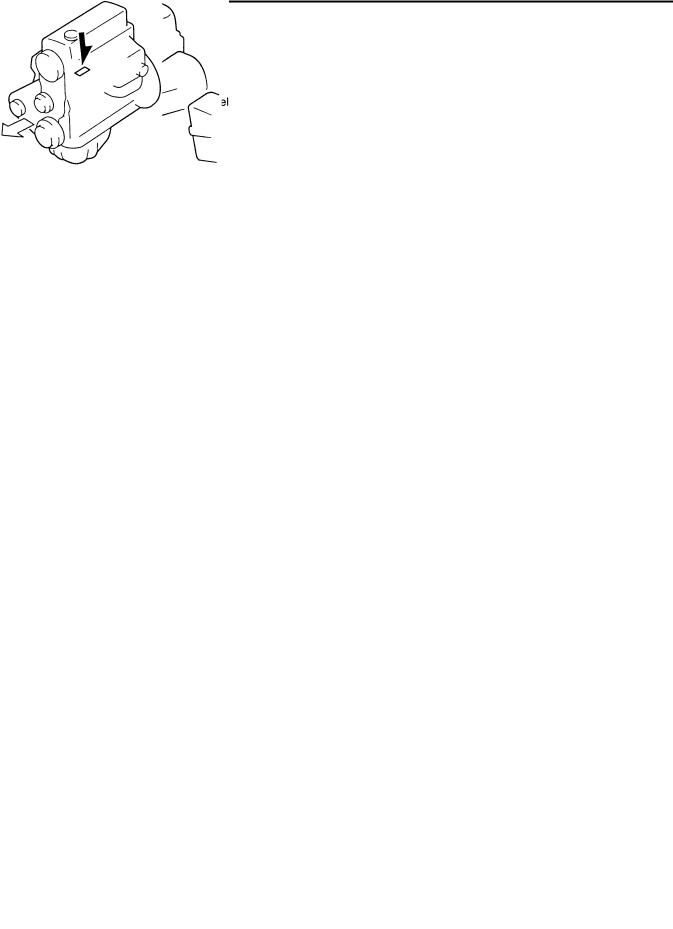
Data Link Connector
DInsert the probe into the service hole when connecting a jumper wire to the data link connector.
Caution
D Inserting a jumper wire probe into the data link connector terminal may damage the terminal.
SXU00019
SXU00020
DConnectors can be disconnected by pressing or pulling the lock lever as shown.
SXU00021
Locking Connector
DWhen locking connectors, listen for a click that will indicate they are securely locked.
SXU00022
Inspection
1.When a tester is used to check for continuity or to measure voltage, insert the tester probe from the wiring harness side.
2.Check the terminals of waterproof connectors from the connector side, as they cannot be accessed from the wiring harness side.
CONTINUED
GI–11

BACK.TO.CHAPTER.INDEX |
RANG.DRFT.REPAIR MANUAL PAGES. FROM. MANUAL |
TO. MODEL .INDEX |
|
|
ELECTRICAL SYSTEM |
Caution
DTo prevent damage to the terminal, wrap a thin wire around the lead before inserting it into the terminal.
SXU00024
Terminals
Inspection
DPull lightly on individual wires to check that they are secured in the terminal.
SXU00025
Replacement
DUse the appropriate tools to remove a terminal as shown. When installing a terminal, be sure to insert it until it locks securely.
DInsert a thin piece of metal from the terminal side of the connector, and then, with the terminal locking tab pressed down, pull the terminal out from the connector.
TYPE A
TYPE B
SXU00026
Sensors, Switches, and Relays
DHandle sensors, switches, and relays carefully. Do not drop them or strike them against other objects.
SXU00027
Wiring Harness
Wiring color codes
DTwo-color wires are indicated by a two-color code symbol.
DThe first letter indicates the base color of the wire and the second the color of the stripe.
CODE |
COLOR |
|
CODE |
COLOR |
B |
Black |
|
O |
Orange |
BR |
Brown |
|
P |
Pink |
G |
Green |
|
R |
Red |
GY |
Gray |
|
V |
Violet |
L |
Blue |
|
W |
White |
LB |
Light Blue |
|
Y |
Yellow |
LG |
Light Green |
|
|
|
B/R |
|
|
BR/Y |
|
|
BLACK |
|
|
BROWN |
|
RED |
|
|
YELLOW |
SXU00028
Fuse
Replacement
1.When replacing a fuse, be sure to replace it with one of the specified capacity. If a fuse again fails after it has been replaced, the circuit probably has a short and the wiring should be checked.
2.Be sure the negative battery terminal is disconnected before replacing a main fuse.
SXU00029
CONTINUED
GI–12
BACK.TO.CHAPTER.INDEX |
RANG.DRFT.REPAIR MANUAL PAGES. FROM. MANUAL |
TO. MODEL .INDEX |
|
|
ELECTRICAL SYSTEM |
3. When replacing a pullout fuse, use the fuse puller.
PULLER
FUSE
SXU00030
ELECTRICAL TROUBLESHOOTING TOOLS
Jumper Wire
DA jumper wire is used to create a temporary circuit. Connect the jumper wire between the terminals of a circuit to bypass a switch.
Caution
D Do not connect a jumper wire from the power source line to a body ground; this may cause burning or other damage to wiring harnesses or electronic components.
Voltmeter
DThe DC voltmeter is used to measure circuit voltage. A voltmeter with a range of 15 V or more is used by connecting the positive (+) probe (red lead wire) to the point where voltage is to be measured and the negative (–) probe (black lead wire) to a body ground.
Ohmmeter
DThe ohmmeter is used to measure the resistance between two points in a circuit, and to check for continuity and short circuits.
Caution
D Do not connect the ohmmeter to any circuit to which voltage is applied. This will damage the ohmmeter.
POWER SOURCE LINE
GROUND LINE
OHMMETER |
SXU00034 |
VOLTMETER |
POWER SOURCE LINE |
BLACK LEAD
RED LEAD
GROUND
CONTINUED
GI–13
BACK.TO.CHAPTER.INDEX |
RANG.DRFT.REPAIR MANUAL PAGES. FROM. MANUAL |
|
TO. MODEL .INDEX |
||
|
JACKING POSITIONS, VEHICLE LIFT (2 SUPPORTS) POSITIONS,
SAFETY STAND POSITIONS
JACKING POSITIONS |
REAR |
Warning
DImproperly jacking a vehicle is dangerous. The vehicle can slip off the jack and cause serious injury. Use only the correct front and rear jacking positions and block the wheels.
Use safety stands to support the vehicle after it has been lifted.
FRONT
SAFETY STAND POSITIONS
FRONT
REAR
REAR
VEHICLE LIFT (2 SUPPORTS)
POSITIONS
FRONT
CONTINUED
GI–14
BACK.TO.CHAPTER.INDEX |
RANG.DRFT.REPAIR MANUAL PAGES. FROM. MANUAL |
|
TO. MODEL .INDEX |
||
|
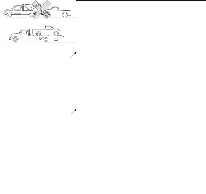
TOWING
TOWING
Proper lifting and towing are necessary to prevent damage to the vehicle.
Government and local laws must be followed.
Wheel dollies
Wheel dollies
Caution
DDo not tow with sling-type equipment. This could damage your vehicle. Use wheel-lift or flatbed equipment.
(With Manual Transmission)
If the transmission, rear axle, and steering system are not damaged, the vehicle may be towed on all four wheels. If any of these components are damaged, use wheel dollies.
(With Automatic Transmission)
If excessive damage or other conditions prevent towing the vehicle with the driving wheels off the ground, use wheel dollies.
If all four wheels are on the ground, the vehicle may be towed only forward. Do not exceed 45 km/h (28 mph) and a distance of 15 km (9.3 miles); you could damage the transmission.
If speed must exceed 45 km/h (28 mph) or a towing distance of 15 km (9.3 miles), use one of these methods:
DPlace the rear wheels on dollies.
DTow with the rear wheels off the ground.
DDisconnect the propeller shaft.
If the transmission or rear axle is inoperative, tow with the rear wheels off the ground.
Caution
DFollow these instructions when towing the vehicle with all wheels on the ground or with the front wheels on the ground and the rear wheels raised.
(4 4 Model)
1.Put the transfer case in 2H.
2.Set the transfer case at 2H and the hubs at FREE.
(All Models)
1.Set the transmission in neutral.
2.Turn the engine switch to ACC position.
3.Release the parking brake.
DRemember that power assist for the brakes and steering will not be available when the engine is not running.
If your Ford/Mazda has 4 4, change to 2-wheel drive before having the vehicle towed. If this is not possible, tow with all four wheels raised.
CONTINUED
GI–15
BACK.TO.CHAPTER.INDEX |
RANG.DRFT.REPAIR MANUAL PAGES. FROM. MANUAL |
|
TO. MODEL .INDEX |
||
|
TOWING, IDENTIFICATION NUMBER LOCATIONS
TOWING HOOKS
Caution
DThe towing hooks should be used only in an emergency (e.g. to get the vehicle out of a ditch or a snow bank).
DWhen using the towing hooks, always pull the cable or chain in a straight direction with respect to the hook. Apply no sideways force.
FRONT 4 4
TIEDOWN HOOKS
Caution
DDo not use the hook loops under the front for towing. They are designed ONLY for tying down the vehicle when it is being transported. Using them for towing will damage the bumper.
FRONT 4 2
IDENTIFICATION NUMBER LOCATIONS
VEHICLE IDENTIFICATION NUMBER
ENGINE IDENTIFICATION NUMBER G6
WL, WL Turbo
F2 CIS
F2 CARB
4 4
CONTINUED
GI–16

BACK.TO.CHAPTER.INDEX |
RANG.DRFT.REPAIR MANUAL PAGES. FROM. MANUAL |
TO. MODEL .INDEX |
|
|
NEW STANDARDS |
NEW STANDARDS
D Following is a comparison of the previous standard and the new standard.
|
New Standard |
|
Previous Standard |
Remark |
|
Abbreviation |
Name |
Abbreviation |
Name |
||
|
|||||
|
|
|
|
|
|
AP |
Accelerator Pedal |
— |
Accelerator Pedal |
|
|
ACL |
Air Cleaner |
— |
Air Cleaner |
|
|
A/C |
Air Conditioning |
— |
Air Conditioning |
|
|
BARO |
Barometric Pressure |
— |
Atmospheric Pressure |
|
|
B) |
Battery Positive Voltage |
VB |
Battery Voltage |
|
|
— |
Brake Switch |
— |
Stoplight Switch |
|
|
— |
Calibration Resistor |
— |
Corrected Resistance |
#6 |
|
CMP |
Camshaft Position Sensor |
— |
Crank Angle Sensor |
|
|
sensor |
|
||||
|
|
|
|
||
CAC |
Charge Air Cooler |
— |
Intercooler |
|
|
CLS |
Closed Loop System |
— |
Feedback System |
|
|
CTP |
Closed Throttle Position |
— |
Fully Closed |
|
|
— |
Closed Throttle Position Switch |
— |
Idle Switch |
|
|
CPP |
Clutch Pedal Position |
— |
Clutch Position |
|
|
CIS |
Continuous Fuel Injection System |
EGI |
Electronic Gasoline Injection System |
|
|
CS sensor |
Control Sleeve Sensor |
CSP |
Control Sleeve Position Sensor |
#6 |
|
sensor |
|||||
|
|
|
|
||
CKP |
Crankshaft Position Sensor |
— |
Crank Angle Sensor 2 |
|
|
sensor |
|
||||
|
|
|
|
||
DLC |
Data Link Connector |
— |
Diagnosis Connector |
|
|
DTM |
Diagnostic Test Mode |
— |
Test Mode |
#1 |
|
DTC |
Diagnostic Trouble Code(s) |
— |
Service Code(s) |
|
|
DI |
Distributor Ignition |
— |
Spark Ignition |
|
|
DLI |
Distributorless Ignition |
— |
Direct Ignition |
|
|
EI |
Electronic Ignition |
— |
Electronic Spark Ignition |
#2 |
|
ECT |
Engine Coolant Temperature |
— |
Water Thermo |
|
|
EM |
Engine Modification |
— |
Engine Modification |
|
|
— |
Engine Speed Input Signal |
— |
Engine RPM Signal |
|
|
EVAP |
Evaporative Emission |
— |
Evaporative Emission |
|
|
EGR |
Exhaust Gas Recirculation |
— |
Exhaust Gas Recirculation |
|
|
FC |
Fan Control |
— |
Fan Control |
|
|
FF |
Flexible Fuel |
— |
Flexible Fuel |
|
|
4GR |
Fourth Gear |
— |
Overdrive |
|
|
— |
Fuel Pump Relay |
— |
Circuit Opening Relay |
#3 |
|
FSO |
Fuel Shut Off Solenoid |
FCV |
Fuel Cut Valve |
#6 |
|
solenoid |
|||||
|
|
|
|
||
GEN |
Generator |
— |
Alternator |
|
|
GND |
Ground |
— |
Ground/Earth |
|
|
HO2S |
Heated Oxygen Sensor |
— |
Oxygen Sensor |
With heater |
|
IAC |
Idle Air Control |
— |
Idle Speed Control |
|
|
— |
Incorrect Gear Ratio |
— |
— |
|
#1: Diagnostic trouble codes depend on the diagnostic test mode #2: Controlled by the PCM
#3: In some models, there is a fuel pump relay that controls pump speed. That relay is now called the fuel pump
relay (speed). |
|
#6: Part name of diesel engine |
CONTINUED |
|
GI–17
BACK.TO.CHAPTER.INDEX |
|
RANG.DRFT.REPAIR MANUAL PAGES. FROM. MANUAL |
||||||
|
|
TO. MODEL .INDEX |
||||||
|
|
|
NEW STANDARDS |
|||||
|
|
|
|
|
|
|||
|
|
|
|
|
|
|
|
|
|
|
|
|
|
|
|
|
|
|
|
|
New Standard |
|
Previous Standard |
Remark |
|
|
|
Abbreviation |
Name |
Abbreviation |
Name |
|
|||
|
|
|
|
|||||
|
|
|
|
|
|
|
|
|
|
|
— |
Injection Pump |
FIP |
Fuel Injection Pump |
#6 |
|
|
|
|
— |
Input/Turbine Speed Sensor |
— |
Pulse Generator |
|
|
|
|
|
IAT |
Intake Air Temperature |
— |
Intake Air Thermo |
|
|
|
|
|
KS |
Knock Sensor |
— |
Knock Sensor |
|
|
|
|
|
MIL |
Malfunction Indicator Lamp |
— |
Malfunction Indicator Light |
|
|
|
|
|
MAP |
Manifold Absolute Pressure |
— |
Intake Air Pressure |
|
|
|
|
|
MAF |
Mass Air Flow Sensor |
— |
Airflow Sensor |
|
|
|
|
|
sensor |
|
|
|
|||
|
|
|
|
|
|
|
|
|
|
|
MFL |
Multiport Fuel Injection |
— |
Multiport Fuel Injection |
|
|
|
|
|
OBD |
On-Board Diagnostic |
— |
Diagnosis/Self-Diagnosis |
|
|
|
|
|
OL |
Open Loop |
— |
Open Loop |
|
|
|
|
|
— |
Output Speed Sensor |
— |
Vehicle Speed Sensor 1 |
|
|
|
|
|
OC |
Oxidation Catalytic Converter |
— |
Catalytic Converter |
|
|
|
|
|
O2S |
Oxygen Sensor |
— |
Oxygen Sensor |
|
|
|
|
|
PNP |
Park/Neutral Position |
— |
Park/Neutral Range |
|
|
|
|
|
— |
PCM Control Relay |
— |
Main Relay |
#6 |
|
|
|
|
PSP |
Power Steering Pressure |
— |
Power Steering Pressure |
|
|
|
|
|
PCM |
Powertrain Control Module |
ECU |
Engine Control Unit |
#4 |
|
|
|
|
— |
Pressure Control Solenoid |
— |
Line Pressure Solenoid Valve |
|
|
|
|
|
PAIR |
Pulsed Secondary Air Injection |
— |
Secondary Air Injection System |
Pulsed |
|
|
|
|
injection |
|
|||||
|
|
|
|
|
|
|
||
|
|
— |
Pump Speed Sensor |
— |
NE Sensor |
#6 |
|
|
|
|
AIR |
Secondary Air Injection |
— |
Secondary Air Injection System |
Injection with |
|
|
|
|
air pump |
|
|||||
|
|
|
|
|
|
|
||
|
|
SAPV |
Secondary Air Pulse Valve |
— |
Reed Valve |
|
|
|
|
|
SFI |
Sequential Multipoint Fuel Injection |
— |
Sequential Fuel Injection |
|
|
|
|
|
— |
Shift Solenoid A |
— |
1–2 Shift Solenoid Valve |
|
|
|
|
|
— |
Shift A Solenoid Valve |
|
|
|
||
|
|
|
|
|
|
|
||
|
|
— |
Shift Solenoid B |
— |
2–3 Shift Solenoid Valve |
|
|
|
|
|
— |
Shift B Solenoid Valve |
|
|
|
||
|
|
|
|
|
|
|
||
|
|
— |
Shift Solenoid C |
— |
3–4 Shift Solenoid Valve |
|
|
|
|
|
3GR |
Third Gear |
— |
3rd Gear |
|
|
|
|
|
TWC |
Three Way Catalytic Converter |
— |
Catalytic Converter |
|
|
|
|
|
TB |
Throttle Body |
— |
Throttle Body |
|
|
|
|
|
TP sensor |
Throttle Position Sensor |
— |
Throttle Sensor |
|
|
|
|
|
TCV |
Timer Control Valve |
TCV |
Timing Control Valve |
#6 |
|
|
|
|
TCC |
Torque Converter Clutch |
— |
Lock-up Position |
|
|
|
|
|
TCM |
Transmission (Transaxle) Control |
— |
EC-AT Control Unit |
|
|
|
|
|
Module |
|
|
|
|||
|
|
|
|
|
|
|
|
|
|
|
— |
Transmission (Transaxle) Fluid |
— |
ATF Thermosensor |
|
|
|
|
|
Temperature Sensor |
|
|
|
|||
|
|
|
|
|
|
|
|
|
|
|
TR |
Transmission (Transaxle) Range |
— |
Inhibitor Position |
|
|
|
|
|
TC |
Turbocharger |
— |
Turbocharger |
|
|
|
|
|
VSS |
Vehicle Speed Sensor |
— |
Vehicle Speed Sensor |
|
|
|
|
|
VR |
Voltage Regulator |
— |
IC Regulator |
|
|
|
#4: Device that controls engine and powertrain #6: Part name of diesel engine
CONTINUED
GI–18
BACK.TO.CHAPTER.INDEX |
|
|
RANG.DRFT.REPAIR MANUAL PAGES. FROM. MANUAL |
||||||
|
|
|
TO. MODEL .INDEX |
||||||
|
|
|
NEW STANDARDS, ABBREVIATIONS |
||||||
|
|
|
|
|
|
||||
|
|
|
|
|
|
|
|
|
|
|
|
|
|
|
|
|
|
|
|
|
|
|
New Standard |
|
|
Previous Standard |
Remark |
|
|
|
Abbreviation |
Name |
Abbreviation |
Name |
|
||||
|
|
|
|
||||||
|
|
|
|
|
|
|
|
|
|
|
VAF |
Volume Air Flow Sensor |
|
— |
Air flow Sensor |
|
|
|
|
|
sensor |
|
|
|
|
||||
|
|
|
|
|
|
|
|
||
|
WU-TWC |
Warm Up Three Way Catalytic |
|
— |
Catalytic Converter |
#5 |
|
|
|
|
Converter |
|
|
|
|||||
|
|
|
|
|
|
|
|
|
|
|
WOT |
Wide Open Throttle |
|
— |
Fully Open |
|
|
|
|
|
#5: Directly |
connected to exhaust manifold |
|
|
|
|
|
|
|
|
ABBREVIATIONS |
|
|
|
|
|
|
||
|
ACC . . . . . . |
. . . . . . . . Accessories |
|
|
|
|
|
|
|
|
ATDC . . . . . |
. . . . . . . . After top dead center |
|
|
|
|
|
|
|
|
ATF . . . . . . . |
. . . . . . . . Automatic transmission fluid |
|
|
|
|
|
|
|
|
BTDC . . . . . |
. . . . . . . . Before top dead center |
|
|
|
|
|
|
|
|
CARB . . . . . |
. . . . . . . . Carburetor |
|
|
|
|
|
|
|
|
ELR . . . . . . |
. . . . . . . . Emergency locking retractor |
|
|
|
|
|
|
|
|
EX |
. . . . . . . |
. . . . . . . . Exhaust |
|
|
|
|
|
|
|
FIP |
. . . . . . . |
. . . . . . . . Fuel injection pump |
|
|
|
|
|
|
|
HI |
. . . . . . . . |
. . . . . . . . High |
|
|
|
|
|
|
|
HLA . . . . . . |
. . . . . . . . Hydraulic lash adjuster |
|
|
|
|
|
|
|
|
IG |
. . . . . . . . |
. . . . . . . . Ignition |
|
|
|
|
|
|
|
IN |
. . . . . . . . |
. . . . . . . . Intake |
|
|
|
|
|
|
|
INT . . . . . . . |
. . . . . . . . Intermittent |
|
|
|
|
|
|
|
|
LH |
. . . . . . . . |
. . . . . . . . Left hand |
|
|
|
|
|
|
|
L.H.D. . . . . . |
. . . . . . . . Left hand drive |
|
|
|
|
|
|
|
|
LO |
. . . . . . . |
. . . . . . . . Low |
|
|
|
|
|
|
|
LSD . . . . . . |
. . . . . . . . Limited slip differential |
|
|
|
|
|
|
|
|
LSPV . . . . . |
. . . . . . . . Load sensing proportioning valve |
|
|
|
|
|
||
|
M |
. . . . . . . . |
. . . . . . . . Motor |
|
|
|
|
|
|
|
MAX . . . . . . |
. . . . . . . . Maximum |
|
|
|
|
|
|
|
|
MFW . . . . . |
. . . . . . . . Manual freewheel |
|
|
|
|
|
|
|
|
MIN . . . . . . |
. . . . . . . . Minimum |
|
|
|
|
|
|
|
|
P/S . . . . . . . |
. . . . . . . . Power steering |
|
|
|
|
|
|
|
|
RFW . . . . . . |
. . . . . . . . Remote freewheel |
|
|
|
|
|
|
|
|
RH |
. . . . . . . |
. . . . . . . . Right hand |
|
|
|
|
|
|
|
R.H.D. . . . . . . . . . . . . Right hand drive |
|
|
|
|
|
|
||
|
SAS . . . . . . |
. . . . . . . . Sophisticated air bag sensor |
|
|
|
|
|
|
|
|
SST . . . . . . |
. . . . . . . . Special service tool |
|
|
|
|
|
|
|
|
TNS . . . . . . |
. . . . . . . . Tail number side lights |
|
|
|
|
|
|
|
|
2WD . . . . . . |
. . . . . . . . 2 wheel drive |
|
|
|
|
|
|
|
|
4WD . . . . . . |
. . . . . . . . 4 wheel drive |
|
|
|
|
|
|
|
|
4 |
2 . . . . . . |
. . . . . . . . 4 wheel – 2 drive |
|
|
|
|
|
|
|
4 |
4 . . . . . . |
. . . . . . . . 4 wheel – 4 drive |
|
|
|
CONTINUED |
||
|
|
|
|
|
|
|
|||
GI–19

BACK.TO.CHAPTER.INDEX |
RANG.DRFT.REPAIR MANUAL PAGES. FROM. MANUAL |
|||
TO. MODEL .INDEX |
||||
|
|
|||
|
|
PRE-DELIVERY INSPECTION |
|
|
PRE-DELIVERY INSPECTION
PRE-DELIVERY INSPECTION TABLE
Following items may be done at any time prior to delivery to your customer.
EXTERIOR
INSPECT and ADJUST, if necessary, the following items to the specifications:
Glass, exterior bright metal and paint for damage Wheel lug nuts
Tire pressures
All weatherstrips for damage or detachment Operation of bonnet release and lock
Door operation and alignment
Headlight aiming INSTALL the following parts:
Wheel caps
UNDER BONNET-ENGINE OFF
INSPECT and ADJUST, if necessary, the following items to the specifications:
Fuel, coolant and hydraulic lines, fittings, connections and components for leaks
Engine oil level
Power steering fluid level (if equipped) Brake and clutch master cylinder fluid levels Windshield washer reservoir fluid level Radiator coolant and specific gravity Tightness of water hose clamps
Tightness of battery terminals, electrolyte level and specific gravity
Drive belt tensions
Accelerator cable and linkage for free movement CLEAN the spark plugs
INTERIOR
INSTALL the following parts Fuse for accessories
CHECK the operation of the following items:
Seat controls (sliding and reclining) and headrest Door locks
Ignition switch (Engine switch) and steering lock All lights including warning and indicator lights Horn, windshield wipers and washers (if equipped)
Wiper blades performance Clean the wiper blades and windshield
Antenna
Cigarette lighter and clock Tilt steering (if equipped)
Air conditioner at various modes (if equipped) CHECK the following items:
Presence of spare fuse Upholstery and interior finish
CHECK and ADJUST, if necessary, the following items: Operation and fit of windows
Pedal height and free play of brake and clutch pedals Parking brake
UNDER BONNET-ENGINE RUNNING AT
OPERATING TEMPERATURE
CHECK the following items:
Operation of dashpot
Initial ignition timing
Injection timing
Idle speed
Operation of throttle position sensor
ON HOIST
CHECK the following items: Operation of freewheel hubs Manual transmission oil level Transfer oil level
Front differential oil level Rear differential oil level
Underside fuel, coolant and hydraulic lines, fittings, connections and components for leaks
Tires for cuts or bruises
Steering linkage, suspension, exhaust system and all underside hardware for looseness or damage
ROAD TEST
CHECK the following items: Brake operation
Clutch operation Steering control
Operation of meters and gauges 3 Squeaks, rattles or unusual noise
Engine general performance Emergency locking retractors Operation of transfer
AFTER ROAD TEST
REMOVE seat and floor mat protective covers CHECK for necessary owner's information material, tools and spare tire in vehicle
CONTINUED
Gl-20

BACK.TO.MAIN.INDEX |
RANG.DRFT.REPAIR MANUAL PAGES. FROM. MANUAL |
|
TO. MODEL .INDEX |
||
|
||
|
ENGINE |
|
|
(G6) |
DRIVE BELT ................................................................ |
B1-1 |
DRIVE BELT INSPECTION ................................ |
B1-1/2 |
DRIVE BELT ADJUSTMENT ............................. |
B1-2 |
COMPRESSION INSPECTION .................................. |
B1-2 |
TIMING CHAIN ............................................................. |
B1-3 |
TIMING CHAIN REMOVAL/ |
B1-3/5 |
INSTALLATION .................................................... |
|
CYLINDER HEAD GASKET .................................. |
B1-6 |
CYLINDER HEAD GASKET |
B1-6/9 |
REPLACEMENT ................................................. |
|
HYDRAULIC LASH ADJUSTER (HLA)................. |
B1-10 |
HLA REMOVAL/INSTALLATION ..................... |
B1-10/11 |
HLA TROUBLESHOOTING ............................. |
B1-12 |
FRONT OIL SEAL....................................................... |
B1-13 |
FRONT OIL SEAL REPLACEMENT................. |
B1-13 |
REAR OIL SEAL ......................................................... |
B1-14 |
REAR OIL SEAL REPLACEMENT .................. |
B1-14 |
ENGINE ....................................................................... |
B1-15 |
ENGINE REMOVAL/INSTALLATION .............. |
B1-15/16 |
ENGINE DISASSEMBLY/ASSEMBLY .............. |
B1-17 |
DRIVE BELT
DRIVE BELT INSPECTION
Drive Belt Deflection Check
1.Check the drive belt deflection when the engine is cold, or at least 30 minutes after the engine has been stopped. Apply pressure 98 N {10 kgf, 22 Ibf} midway between the specified pulleys.
Deflection |
|
mm {in} |
|
|
|
||
Drive belt |
*New |
Used |
|
Generator |
10.0—12.0 |
12.0—14.0 |
|
{0.40—0.47} |
{0.48—0.55} |
||
|
|||
P/S |
6.6—7.2 |
7.2—8.0 |
|
{0.26—0.28} |
{0.29—0.31} |
||
|
|||
A/C |
8.5—10.0 |
10.0—11.5 |
|
{0.34—0.39} |
{0.40—0.45} |
||
|
*: A belt that has been on a running engine for less than five minutes.
2.If the deflection is not within the specification, adjust it. (Refer to DRIVE BELT, DRIVE BELT ADJUSTMENT.)
Drive Belt Tension Check
1.Belt tension can be checked in place of belt deflection. Check the drive belt tension when the engine is cold, or at least 30 minutes after the engine has been stopped. Using the SST, check the belt tension between any two pulleys.
|
|
N {kgf, Ibf} |
|
Drive belt |
*New |
Used |
|
Generator |
491-588 |
393-490 |
|
{50-60,110-132} |
{40-50,88-110} |
||
|
|||
P/S |
412—470 |
354—402 |
|
{42-48,93—105} |
{36-41, 80—90} |
||
|
|||
|
557—641 |
471—556 |
|
A/C |
{56.7—65.4, |
{48.0—56.7, |
|
|
125—143} |
106—124} |
* A belt that has been on a running engine for less than five minutes.
CONTINUED
B1-1

BACK.TO.CHAPTER.INDEX |
RANG.DRFT.REPAIR MANUAL PAGES. FROM. MANUAL |
|||
TO. MODEL .INDEX |
||||
|
|
|||
|
|
DRIVE BELT, COMPRESSION INSPECTION |
|
|
2.If the tension is not within the specification, adjust it. (Refer to DRIVE BELT, DRIVE BELT ADJUSTMENT.)
DRIVE BELT ADJUSTMENT
1.Loosen mounting bolts A and B, and locknut C.
2.Adjust the belt deflection or tension by turning the adjusting bolt D.
(Refer to DRIVE BELT, DRIVE BELT INSPECTION.)
3.Tighten mounting bolts A and B and locknut C.
COMPRESSION INSPECTION
Warning
•When the engine and the oil are hot, they can badly burn. Be careful not to burn yourself during removal/installation of each component.
1.Verify that the battery is fully charged. Recharge it if necessary.
(Refer to section G, CHARGING SYSTEM, BATTERY INSPECTION, Battery.)
2.Warm up the engine to the normal operating temperature.
3.Stop the engine and allow it to cool off for about 10 minutes.
4.Perform "Fuel Line Safety Procedure". Leave the fuel pump relay removed.
(Refer to section F1, FUEL SYSTEM, BEFORE REPAIR PROCEDURE.)
5.Disconnect the igniter connector.
(Refer to section G, IGNITION SYSTEM, IGNITION COIL REMOVAL/INSTALLATION.)
6.Remove the spark plugs.
7.Connect a compression gauge into the No.1 spark plug hole.
8.Fully depress the accelerator pedal and crank the engine.
9.Note the maximum gauge reading.
10.Inspect compression of each cylinder.
Compression |
kPa {kgf/cm2, psi} [rpm] |
|
|
||
Item |
Engine type |
|
G6 |
||
|
||
Standard |
1255 {12.8, 182} [270] |
|
Minimum |
882.6 {9.0, 128} [270] |
|
Maximum |
196 kPa {2.0 kgf/cm2, 28 psi} |
|
difference between |
|
11.If the compression in one or more cylinders is low or the compression difference between cylinders exceeds the maximum, pour a small amount of clean engine oil into the cylinder and recheck the compression.
(1)If the compression increases, the piston, the piston rings, or cylinder wall may be worn and overhaul is required.
(2)If the compression stays low, a valve may be stuck or improperly seated and overhaul is required.
(3)If the compression in adjacent cylinders stays low, the cylinder head gasket may be damaged or the cylinder head distorted and overhaul is required.
12.Disconnect the compression gauge.
13.Install the spark plugs.
Tightening torque
15—22 N.m {1.5—2.3 kgf.m, 11—l6ft.lbf}
14.Connect the igniter connector.
15.Install the fuel pump relay.
CONTINUED
B1-2
BACK.TO.CHAPTER.INDEX |
RANG.DRFT.REPAIR MANUAL PAGES. FROM. MANUAL |
|||
TO. MODEL .INDEX |
||||
|
|
|||
|
|
TIMING CHAIN |
|
|
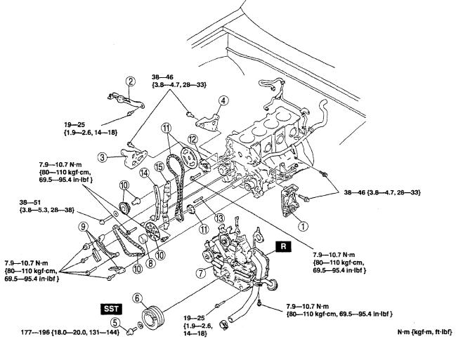
TIMING CHAIN
TIMING CHAIN REMOVAL/INSTALLATION
1.Disconnect the negative battery cable.
2.Remove the generator.
3.Remove the P/S oil pump with the oil hose still connected. Position the P/S oil pump so that it is out of the way. (Refer to section N, ENGINE SPEED SENSING POWER STEERING, POWER STEERING OIL PUMP REMOVAL/INSTALLATION.)
4.Remove the A/C compressor with the pipe still connected. Position the A/C compressor so that it is out of the way.
5.Remove the cylinder head.
(Refer to CYLINDER HEAD GASKET, CYLINDER HEAD GASKET REPLACEMENT.)
6.Remove the water pump. (Refer to section E, WATER PUMP, WATER PUMP REMOVAL/INSTALLATION.)
7.Remove the oil pan. (Refer to section D, OIL PAN, OIL PAN REMOVAL/INSTALLATION.)
8.Disconnect the oil strainer stay.
9.Remove in the order indicated in the table.
10.Install in the reverse order of removal.
11.Start the engine and check for engine oil and engine coolant leakage.
1 |
A/C compressor bracket |
|
10 |
Balancer chain, idler sprocket, crankshaft sprocket |
|
|
|
|
|
Installation Note |
|
2 |
Generator strap |
|
|
||
|
|
|
11 |
Timing chain, timing sprocket, camshaft sprocket |
|
3 |
P/S oil pump bracket |
|
|
||
|
|
Installation Note |
|
||
|
|
|
|
|
|
4 |
Generator bracket |
|
|
|
|
|
|
|
|
||
|
12 |
Chain adjuster |
|
||
5 |
Pulley lock bolt |
|
|
||
|
|
Installation Note |
|
||
|
Removal/Installation Note |
|
|
|
|
|
|
13 |
Key |
|
|
6 |
Crankshaft pulley |
|
|
|
|
|
14 |
Timing chain lever |
|
||
7 |
Chain cover |
|
|
||
|
|
Installation Note |
|
||
8 |
Spacer |
|
15 |
Timing chain guide |
|
9 |
Balancer chain guide |
|
|
|
|
|
Installation Note |
|
|
CONTINUED |
|
|
|
B1-3 |
|||
|
|
||||
|
|
|
|
||

BACK.TO.CHAPTER.INDEX |
RANG.DRFT.REPAIR MANUAL PAGES. FROM. MANUAL |
|||
TO. MODEL .INDEX |
||||
|
|
|||
|
|
TIMING CHAIN |
|
|
Pulley Lock Bolt Removal/Installation Note
•Hold the crankshaft using the SST.
Timing Chain Lever Installation Note
•Install the chain lever and verify that it moves smoothly in the direction indicated.
Chain Adjuster Installation Note
•Push the chain adjuster sleeve in (toward the left) and insert the pin as shown into the lever to hold the sleeve.
2.Assemble the camshaft sprocket to the timing chain so that the timing mark of camshaft sprocket is aligned with the white link of timing chain as shown.
3.Secure the camshaft sprocket and the timing chain with a wire to prevent disengagement.
Balancer Chain, Idler Sprocket, Crankshaft Sprocket Installation Note
1. Install the crankshaft sprocket as shown.
2. Assemble the idler sprocket on to the idler shaft.
3.Set the balancer chain on the idler sprocket so that the timing mark of the idler sprocket is aligned with the brown link of the balancer chain as shown.
Timing Chain, Timing Sprocket, Camshaft
Sprocket Installation Note
1.Install the timing chain and timing sprocket so that the white link of the timing chain is aligned with the timing mark of the timing sprocket as shown.
CONTINUED
B1-4

BACK.TO.CHAPTER.INDEX
TIMING CHAIN
RANG.DRFT.REPAIR MANUAL PAGES. FROM. MANUAL TO. MODEL .INDEX
4.Install the balancer chain so that the five alignment marks on the chain, sprocket and cylinder block align, and attach the idler sprocket to the cylinder block.
4.Loosen the chain guide C by adjusting bolt E.
5.Push the chain guide C with a force of 49 N {5.0 kgf, 11 Ibf} in the direction of the arrow, then pull back the chain guide 3.2—3.8 mm {0.13—0.14 in] and tighten the adjusting bolt E.
5. Hand-tighten the idler sprocket lock bolt.
Balancer Chain Guide Installation Note
1. Install the chain guide A and B.
Note
•The balancer chain must be replaced if chain guide C bottoms when adjusting.
6.Measure the timing chain slack.
Specification
Approx. 3.0 mm {0.12 in}
2.Install the chain guide C, and tighten the bolt D and hand-tighten the adjusting bolt E.
3. Tighten the idler sprocket lock bolt.
CONTINUED
B1-5
BACK.TO.CHAPTER.INDEX |
RANG.DRFT.REPAIR MANUAL PAGES. FROM. MANUAL |
|||
TO. MODEL .INDEX |
||||
|
|
|||
|
|
CYLINDER HEAD GASKET |
|
|
CYLINDER HEAD GASKET
CYLINDER HEAD GASKET REPLACEMENT
Warning
•Fuel vapor is hazardous. It can very easily ignite, causing serious injury and damage. Always keep sparks and flames away from fuel.
•Fuel line spills and leaks are dangerous. Fuel can ignite and cause serious injuries or death and damage. Fuel can also irritate skin and eyes. To prevent this, always complete the "Fuel Line Safety Procedure" in section F1.
(Refer to section F1, FUEL SYSTEM, BEFORE REPAIR PROCEDURE.)
1.Disconnect the negative battery cable.
2.Drain the engine coolant. (Refer to section E, COOLING SYSTEM SERVICE WARNINGS.) (Refer to section E, ENGINE COOLANT, ENGINE COOLANT REPLACEMENT.)
3.Remove the drive belt. (Refer to DRIVE BELT, DRIVE BELT ADJUSTMENT.)
4.Remove the cooling fan.
5.Remove the front pipe.
6.Remove the air intake pipe and resonance chamber.
7.Disconnect the accelerator cable and bracket.
8.S. Disconnect the vacuum hoses, water hoses, and engine harness connectors.
9.Disconnect the fuel hoses.
(Refer to section F1, FUEL SYSTEM, BEFORE REPAIR PROCEDURE.) (Refer to section F1, FUEL SYSTEM, AFTER REPAIR PROCEDURE.)
10.Remove the intake manifold bracket.
11.Remove the distributor.
(Refer to section G, IGNITION SYSTEM, DISTRIBUTOR REMOVAL/INSTALLATION.)
12.Remove the high-tension lead.
(Refer to section G, IGNITION SYSTEM, HIGH-TENSION LEAD REMOVAL/INSTALLATION.)
13.Remove the spark plug.
14.Remove in the order indicated in the table.
15.Install in the reverse order of removal.
16.Inspect for fuel leakage.
17.Inspect the compression.
(Refer to COMPRESSION INSPECTION.)
18.Start the engine and
(1)check the pulleys and drive belt for runout and contact.
(2)check the ignition timing and idle speed.
(Refer to section F1, ENGINE TUNE-UP.)
CONTINUED
B1-6
BACK.TO.CHAPTER.INDEX |
RANG.DRFT.REPAIR MANUAL PAGES. FROM. MANUAL |
|||
TO. MODEL .INDEX |
||||
|
|
|||
|
|
CYLINDER HEAD GASKET |
|
|
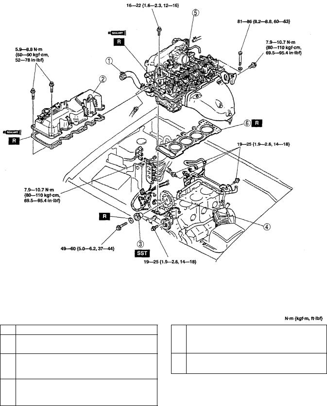
1Upper radiator hose
2Cylinder head cover
Installation Note
3Distributor drive gear
Removal Note
Installation Note
4Camshaft sprocket
Removal Note
Installation Note
5Cylinder head
Removal Note
Installation Note
6Cylinder head gasket
Installation Note
CONTINUED
B1-7
 Loading...