


New Product Introduction
Transit 2006.5 (04/2006-)
Service Information
Technical Service Training
CG 8171/S en 12/2005
TN7002156H
To the best of our knowledge, the illustrations, technical information, data and descriptions in this issue were correct at the time of going to print. The right to change prices, specifications, equipment and maintenance instructions at any time without notice is reserved as part of FORD policy of continuous development and improvement for the benefit of our customers.
No part of this publication may be reproduced, stored in a data processing system or transmitted in any form, electronic, mechanical, photocopy, recording, translation or by any other means without prior permission of Ford-Werke GmbH. No liability can be accepted for any inaccuracies in this publication, although every possible care has been taken to make it as complete and accurate as possible.
Copyright ©2006
Ford-Werke GmbH
Service training programs D-F/GT1 (GB)

Preface
Model year 2006.5 will see the introduction of a modified front end as well as a range of new functions and equipment options for the Transit. Also available will be two new body versions; one with a higher payload as well as a van with medium wheelbase and flat roof (front wheel drive).
As well as the modification of the outer appearance, the interior of the driver cab has also been completely redesigned. In addition to a multitude of storage compartments, the new interior offers the latest generation of audio units, a navigation system, a hands-free kit, a Bluetooth interface and voice control for the phone and audio functions ex works.
The 1,850 kg front axle load version has been added to the range. Disc brakes are installed on the rear axle. Furthermore, stability assist is available as an option.
The previous 2.0L Duratorq TDCi engines have been replaced by a modified generation upgraded to a cubic capacity of 2.2 liters. The 2.4L Duratorq TDCi engine versions have also been modified, while consumption has been reduced. All engines meet emission standard IV.
The vehicle electrical system has undergone significant modification; in addition to providing an instrument cluster with message center it now also permits some custom setting options for the locking system. A second battery (standard on all rear wheel drive versions) as well as a function for charging the radio remote control represent a marked improvement in terms of the power supply.
Protection against theft and ease of repair with regard to the control modules have been notably improved by an innovative Controller Area Network.
The body has again been modified with regard to its crash characteristics. In addition, side air bags and ISOfix mounting points are now available on the Transit for the first time.
You should get to know the new systems, their operation and their function in good time. Only then will you be able to interpret customer complaints correctly and carry out fast and effective diagnoses and/or repairs.
The following product introduction, TN7002156H, CG 8171/S, should provide you with an overview of the vehicle's new systems and components.
Please remember that our training literature has been prepared for FORD TRAINING PURPOSES only. Repairs and adjustments MUST always be carried out according to the instructions and specifications in the workshop literature. Please make full use of the training offered by Ford Technical Training Courses to gain extensive knowledge of both theory and practice.
Service Training (G542739) |
1 |

Table of Contents
|
PAGE |
Preface.............................................................................................................................. |
1 |
At a glance....................................................................................................................... |
5 |
Position of electrical components................................................................................................................................... |
7 |
Lesson 1 – General Information |
|
Lesson 2 – Chassis |
|
Suspension System...................................................................................................................................... |
9 |
Front axle........................................................................................................................................................................ |
9 |
Brake System - General Information........................................................................................................ |
10 |
General............................................................................................................................................................................ |
10 |
ABS system overview..................................................................................................................................................... |
11 |
Bosch 8.0 ABS system.................................................................................................................................................... |
12 |
Active rollover protection............................................................................................................................................... |
13 |
Lesson 3 – Powertrain |
|
Engine System - General Information...................................................................................................... |
14 |
2.2L Duratorq-TDCi (Puma) diesel................................................................................................................................ |
16 |
General................................................................................................................................................................................................... |
16 |
Engine data............................................................................................................................................................................................. |
17 |
Injection system.............................................................................................................................................................. |
19 |
High-pressure pump............................................................................................................................................................................... |
20 |
Fuel injectors.......................................................................................................................................................................................... |
22 |
Valve train.............................................................................................................................................................................................. |
23 |
Accessory drive...................................................................................................................................................................................... |
24 |
2 |
Service Training |

Table of Contents
Cylinder head......................................................................................................................................................................................... |
26 |
Cylinder block........................................................................................................................................................................................ |
28 |
2.4L Duratorq-TDCi (Puma) diesel................................................................................................................................ |
28 |
General................................................................................................................................................................................................... |
28 |
Engine data............................................................................................................................................................................................. |
29 |
Centrifugal oil filter (140 PS version only)............................................................................................................................................ |
31 |
Oil level/temperature sensor (103 kW version only)............................................................................................................................. |
32 |
2.3L Duratec-HE (MI4).................................................................................................................................................. |
33 |
Engine data............................................................................................................................................................................................. |
34 |
Transmission................................................................................................................................................................... |
37 |
Shift mechanism..................................................................................................................................................................................... |
37 |
Clutch assembly.............................................................................................................................................................. |
37 |
Lesson 4 – Electrical |
|
Instrument Cluster..................................................................................................................................... |
38 |
Overview......................................................................................................................................................................... |
38 |
Operation......................................................................................................................................................................... |
40 |
Configuration of the message center (high equipment level)................................................................................................................. |
41 |
Diagnostics............................................................................................................................................................................................. |
41 |
Tachograph.................................................................................................................................................. |
42 |
General............................................................................................................................................................................ |
42 |
Audio System............................................................................................................................................... |
43 |
Overview......................................................................................................................................................................... |
43 |
General............................................................................................................................................................................ |
44 |
Navigation System...................................................................................................................................... |
49 |
Travel Pilot EX................................................................................................................................................................ |
49 |
Service Training |
3 |

Table of Contents
Cellular Phone............................................................................................................................................ |
51 |
General............................................................................................................................................................................ |
51 |
Exterior Lighting........................................................................................................................................ |
53 |
General............................................................................................................................................................................ |
53 |
Communications Network......................................................................................................................... |
54 |
Overview......................................................................................................................................................................... |
54 |
Module Configuration................................................................................................................................ |
57 |
Central module configuration......................................................................................................................................... |
57 |
Module Controlled Functions.................................................................................................................... |
59 |
General............................................................................................................................................................................ |
59 |
Service instructions................................................................................................................................................................................ |
63 |
Power supply................................................................................................................................................................... |
64 |
PATS................................................................................................................................................................................ |
65 |
Multifunction Electronic Modules............................................................................................................ |
66 |
Overview......................................................................................................................................................................... |
66 |
Lesson 5 – Body and Paint |
|
Body............................................................................................................................................................. |
69 |
General............................................................................................................................................................................ |
69 |
Interior.................................................................................................................................................................................................... |
71 |
Anti-corrosion protection....................................................................................................................................................................... |
71 |
End of Life Vehicles Directive............................................................................................................................................................... |
71 |
Central door locking........................................................................................................................................................ |
73 |
SRS.................................................................................................................................................................................. |
77 |
List of Abbreviations....................................................................................................... |
79 |
4 |
Service Training |

Introduction |
At a glance |
Transit 2006.5 (03/2006-)
Internal designation:
•V347 = Front wheel drive
•V348 = Rear wheel drive
Chassis
•Improved drivability through fine-tuning of springs, shock absorbers and steering
•Modified brake system (disc brakes on the rear axle)
•Stability assist with active rollover protection
•Reinforced front axle (for vehicle versions with high payload)
Service Training (G542739) |
5 |

At a glance |
Introduction |
Powertrain
•Modified diesel engines with increased power and lower consumption, emission standard IV, second-generation common-rail technology
•Modified 2.3L Duratec-HE (MI4) engine with emission standard IV, LPG (Liquefied Petroleum Gas) (optional)
•2.4L Duratorq TDCi with 85 kW (115 PS) and 105 kW (143 PS) in conjunction with 6-gear manual transmission (rear wheel drive)
•Gearshift lever in the instrument panel
Electrical system
•Central module configuration
•New GEM (Generic Electronic Module) with integrated PATS (Passive Anti-theft System) function
•Completely newly developed vehicle electrical system with MS-CAN (Controller Area Network) and HS-CAN bus
•New instrument cluster with dot matrix display
•Speed control system
•Power management
•Recharging function for the radio remote control
•Modified locking system with configurable locking functions
•Anti-theft alarm system in accordance with Thatcham CAT 1
•Latest generation of audio units and Travel Pilot EX navigation system
•Hands-free kit with Bluetooth interface and voice control
Body
•Improved crash characteristics
•side air bag modules
•New front end design
•New instrument panel with numerous storage options
•Improved corrosion protection
•Two new vehicle versions
•New exterior colors
•New fabric and leather seats
6 |
(G542739) Service Training |
Introduction |
At a glance |
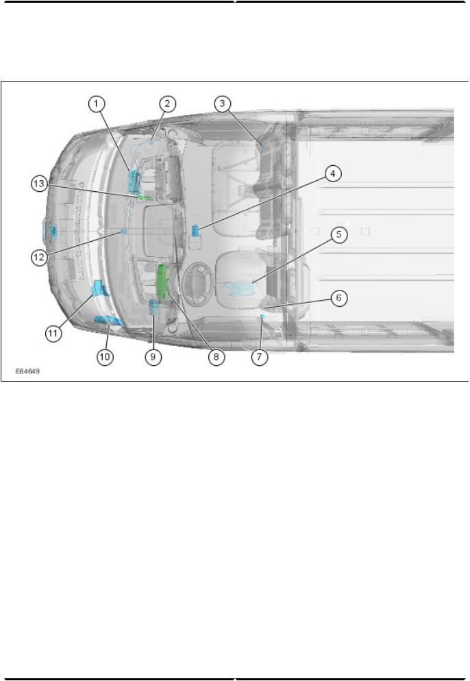
Position of electrical components
Shown: LHD (Left-hand Drive)
1 GEM behind glove compartment, passenger side
IFS (Inertia Fuel Shutoff) (vehicles with petrol
2
engine)
3 Right-hand crash sensor (with side air bag only)
Receiver for radio remote control (in center of
4
headliner)
5Booster heater (vehicle underbody, driver side)
6Trailer module (under driver seat)
7Left-hand crash sensor (with side air bag only)
8Instrument cluster
Hands-free kit/voice control module (beside
9
instrument panel)
PCM (Powertrain Control Module) in left-hand
10
side of engine compartment
ABS (Anti-lock Brake System) module, engine
11
compartment, underneath brake master cylinder
GPS (Global Positioning System) antenna (in
12
center of instrument panel)
RCM (Restraints Control Module) (next to the
13
GEM)
Service Training (G542739) |
7 |
At a glance |
Introduction |
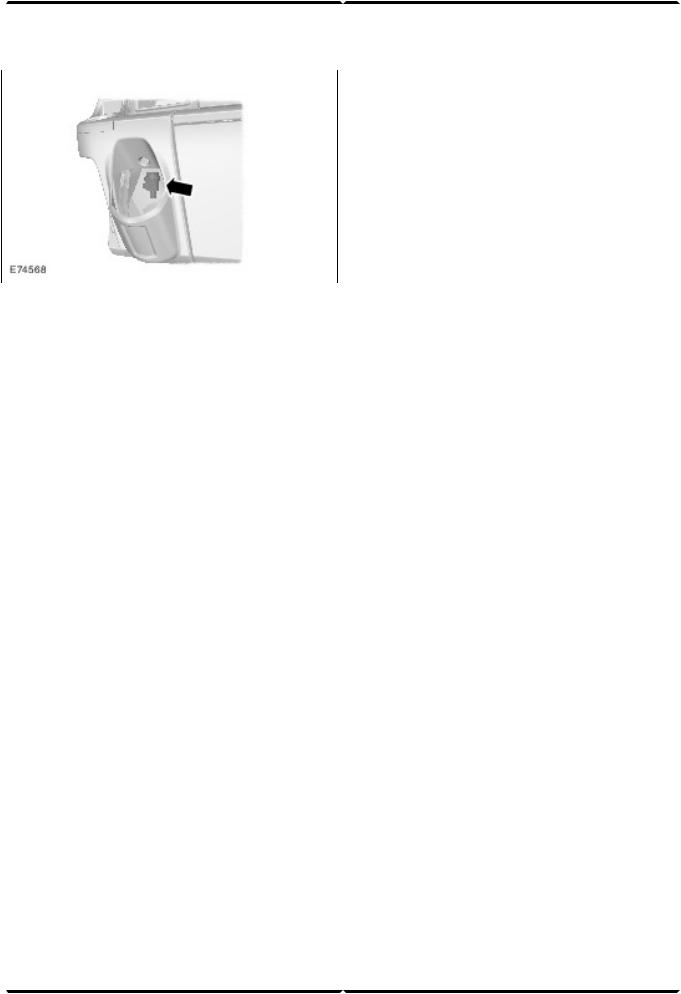
IFS switch
The IFS switch is installed in the instrument panel
(passenger side).
8 |
(G542739) Service Training |
Lesson 2 – Chassis |
Suspension System |
Front axle |
Here the ball joints are bolted between the transverse |
|
control arm and strut and spring assembly (standard: |
|
press-fit) and larger wheel bearings installed. |
|
This requires a new procedure for installation and |
|
removal. Instructions for this can be found in the |
|
relevant Service literature. |
|
Rear axle |
|
In addition to modified suspension points at the rear |
|
axle and a reinforced differential, modified final drive |
|
ratios are also available. |
|
Vehicles with front wheel drive feature a VXT75 manual |
|
transaxle as standard with a final drive ratio of 4,23:1 |
|
or 4,54:1 depending on the payload. |
|
Vehicles with rear wheel drive feature final drive ratios |
|
of 3,73:1 or 5,88:1 in conjunction with MT75 or MT82 |
|
manual transmissions. |
AStrut and spring assembly (reinforced front axle)
BStrut and spring assembly (standard front axle)
In addition to the front axle installed as standard, a reinforced version with a permissible axle load of 1,850 kg is available as an option.
1Press-fit ball joint (standard front axle)
2Bolted ball joint (reinforced front axle)
Service Training (G542798) |
9 |

Brake System - General Information |
Lesson 2 – Chassis |
General
AFront brake
BRear brake
1 Brake pad wear indicator
Larger brake discs as well as modified brake calipers are installed on the front axle depending on the engine.
Disc brakes are installed as standard on the rear axle (except optional version).
The rear brake calipers are similar to those in the Mondeo 2001. The special tool 206-085 is needed to reset the brake caliper piston.
NOTE: To reset the left-hand brake caliper piston, apply pressure to the brake caliper piston while simultaneously turning it counter-clockwise. To reset
the right-hand brake caliper piston, apply pressure to the brake caliper piston while simultaneously turning it clockwise.
All vehicles feature a brake pad wear indicator at the disc brakes. The sensors for the brake pad wear indicator are installed at the inner brake pads and connected in series.
If one of the sensors is interrupted, the instrument cluster registers a missing ground and activates a warning indicator in the instrument cluster.
10 |
(G542740) Service Training |
Lesson 2 – Chassis |
Brake System - General Information |
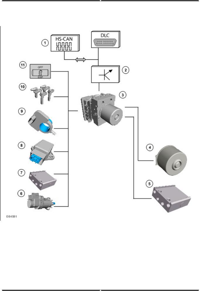
ABS system overview
1HS-CAN data bus input/output signals
2Gateway (GEM)
3ABS module
4ABS motor
5ABS/HCU (Hydraulic Control Unit).
6Stoplamp switch
7 Pressure sensor (in the ABS/HCU)
Yaw rate sensor and lateral acceleration sensor
8
(at the right-hand or left-hand foot controls)
Steering wheel rotation sensor (behind the
9
steering wheel)
10Wheel speed sensors
11Stability assist switch
Service Training (G542740) |
11 |

Brake System - General Information |
Lesson 2 – Chassis |
HS-CAN input signals:
1.CKP (Crankshaft Position) sensor > GEM Gateway
>ABS module
2.Engine idle speed (from PCM) > ABS module
3.Engine status (OFF, idling, stalling) (from PCM) > ABS module
4.Duration of driving cycle (from GEM) > Gateway
>ABS module
5.Tire circumference > GEM Gateway > ABS module
6.Ignition lock position > GEM Gateway > ABS module
7.Torque (from PCM) > ABS module
8.APP (Accelerator Pedal Position) position > GEM Gateway > ABS module
9.BPP (Brake Pedal Position) switch > PCM > ABS module
10.Parking brake switch > GEM Gateway > ABS module
11.Outside air temperature sensor > GEM Gateway > ABS module
12.Total mileage > GEM Gateway > ABS module
13.GEM Gateway > Instrument cluster > Data for central vehicle configuration
HS-CAN output signals:
1.Vehicle speed signal > ABS module > GEM Gateway
2.Intervention BTCS (Brake Traction Control System)
>ABS module > PCM
3.Torque adaptation request > ABS module > PCM
4.ABS module > GEM Gateway > Instrument cluster
>ABS warning indicator
5.ABS module > GEM Gateway > Instrument cluster
>Brake system warning indicator
6.ABS module > GEM Gateway > Instrument cluster
>ABS warning indicator
7.ABS module > GEM Gateway > Instrument cluster > Stability assist warning indicator ESP
8.Signals of all four wheel speed sensors > ABS module > PCM
The following brake systems are available, depending on the vehicle version:
–ABS (Bosch 8.0)
–ABS/BTCS
–ABS/BTCS, stability assist, electronic EBA (Emergency Brake Assist), active rollover protection
Bosch 8.0 ABS system
The Bosch 8.0 ABS system is an enhancement of the previously installed Bosch 5.3 system.
The hydraulic ABS unit and the rear brake calipers are service pre-filled. The front brake calipers and the cylinders of the rear drum brake are not pre-filled.
The steering wheel rotation sensor is integrated together with the clockspring in a housing and is located behind the steering wheel.
The steering wheel rotation sensor works according to the principle of magnetoresistance and permits absolute sensing of the steering wheel position.
NOTE: When replacing the sensor, make sure that the new sensor is installed centrally and is calibrated using WDS (Worldwide Diagnostic System). Instructions for this can be found in the relevant Service literature.
The yaw rate/lateral acceleration sensor is accommodated in a housing and is located on a separate bracket to the left of the foot controls (LHD and RHD (Right-hand Drive)).
Stability assist can be deactivated via a switch in the instrument panel.
12 |
(G542740) Service Training |

Lesson 2 – Chassis |
Brake System - General Information |
Active rollover protection
The active rollover protection (ARM = Active Roll-over
Mitigation) is a function of the stability assist program and is integrated as software in the – ABS/stability assist module as standard. This function does not require any further components.
Operation
If a sudden evasive maneuver by the driver is registered during driving, the outside front wheel is braked for a brief period.
Evasive maneuvers are detected by the steering wheel rotation sensor. For this purpose, a rotational angle speed of more than 512 ° per second must be detected.
The vehicle is stabilized through the braking of the outside front wheel. The active rollover protection is active and effects braking in a vehicle speed range between approx. 30 and 130 km/h.
As soon as the rollover protection is activated, this is indicated by the stability assist warning indicator in the instrument cluster.
If the stability assist is deactivated, the rollover protection nevertheless remains on standby.
Service Training (G542740) |
13 |

Engine System - General Information |
Lesson 3 – Powertrain |
Engine/transmission combinations
1 |
2.2L |
Duratorq-TDCi (Puma) diesel |
4 |
VXT-75 5-speed manual transaxle |
2 |
2.4L |
Duratorq-TDCi (Puma) diesel |
5 |
MT82 6-speed manual transmission |
3 |
2.3L |
Duratec-HE (MI4) |
6 |
MT-75 5-speed manual transmission |
14 |
(G542741) Service Training |

Lesson 3 – Powertrain |
Engine System - General Information |
The Transit 2006.5 (03/2006-) is available with the following engine/transmission combinations:
•2.2L Duratorq-TDCi (Puma) diesel with VXT-75 5-speed manual transaxle (front wheel drive)
•2.4L Duratorq-TDCi (Puma) diesel with MT-75 (5-speed) and MT82 (6-speed) manual transmission
(rear wheel drive)
•2.3L Duratec-HE (MI4) with MT-75 5-speed manual transmission (rear wheel drive)
The engine range consists of the following power versions:
|
Cubic capacity (drive) |
Power output PS (kW) |
Torque (Nm) |
|
2.2L |
(front wheel drive) |
85 |
(63) |
250 |
(previously 2.0L) |
|
|
|
|
|
|
110 (81) |
285 |
|
|
|
130 (96) |
310 |
|
2.4L |
(rear wheel drive) |
100 (74) |
285 |
|
|
|
115 (85) |
320 |
|
|
|
140 |
(103) |
375 |
2.3L |
(rear wheel drive) petrol |
145 |
(107) |
200 |
Service Training (G542741) |
15 |

Engine System - General Information |
Lesson 3 – Powertrain |
2.2L Duratorq-TDCi (Puma) diesel
General
•The previously installed 2.0L TDCi engine will be replaced by a modified 2.2-liter version.
•The 2.2L Duratorq-TDCi (Puma) diesel is essentially based on the previously installed 2.0-liter engine. It is available in three different power output versions of 63 kW, 81 kW and 96 kW.
•The engine features a modified valve train as well as a modified accessory drive.
•The oil change interval is 25,000 km or one year.
•The 63 kW version is the entry-level version for the front wheel drive vehicles. A turbocharger with a wastegate is used.
16 |
(G542741) Service Training |

Lesson 3 – Powertrain |
Engine System - General Information |
•The 81 kW version additionally has oil spray nozzles for cooling the piston crown.
•The 96 kW version has a turbocharger with electrically adjustable guide vane geometry as well as fuel injector nozzles with an increased flow rate.
Injection system
Denso
•Fuel injectors
•High-pressure pump
•Fuel injection supply manifold
Engine management
•Visteon
•EOBD (European On-board Diagnostic) for the monitoring of emissions-related components.
Engine emission control
•Meets emission standard IV
•Electrical EGR (Exhaust Gas Recirculation) valve with water cooling
Diagnosis
•Diagnosis using WDS via the DLC (Data Link Connector).
Engine data
2.2L Duratorq-TDCi
(Puma) diesel
Engine code |
P8FA (85 PS) |
|
QVFA (110 PS) |
|
QWFA (130 PS) |
Cubic capacity |
1,998 ccm |
Stroke |
86 mm |
Bore |
86 mm |
Compression ratio |
19 : 1 |
Firing order |
1-3-4-2 |
Idle speed |
900 rpm |
Max. power output, torque |
63 kW (85 PS) at 3,500 |
|
rpm, 250 Nm at 1,500 rpm |
|
81 kW (110 PS) at 3,500 |
|
rpm, 285 Nm at 1,750 rpm |
|
96 kW (130 PS) at 3,500 |
|
rpm, 310 Nm at 1,600 rpm |
Fuel |
Diesel |
Service Training (G542741) |
17 |

Engine System - General Information |
Lesson 3 – Powertrain |
Power and torque curves
A |
Torque (Nm) |
3 |
Torque curve for 81 kW engine |
B |
Engine speed (rpm) |
4 |
Power curve for 81 kW engine |
C |
Power output (kW) |
5 |
Torque curve for 63 kW engine |
1 |
Torque curve for 96 kW engine |
6 |
Power curve for 63 kW engine |
2 |
Power curve for 96 kW engine |
|
|
18 |
(G542741) Service Training |
Lesson 3 – Powertrain |
Engine System - General Information |
Injection system
1 |
High-pressure pipe |
7 |
Fuel metering valve |
2 |
Leak-off pipe |
8 |
Fuel pressure sensor |
3 |
Fuel injection line |
9 |
Fuel temperature sensor |
4 |
Injector |
10 |
High-pressure pump |
5 |
Pressure relief valve |
11 |
Fuel return |
6 |
Fuel injection supply manifold |
|
|
Service Training (G542741) |
19 |

Engine System - General Information |
Lesson 3 – Powertrain |
The introduction of the Transit 2006.5 (03/2006-) will see the previously used Delphi common-rail system replaced by the Denso common-rail system.
This has achieved an increase in engine power while at the same time reducing fuel consumption.
Fuel injection supply manifold
The pressure relief valve opens at a fuel pressure of approx. 2000 bar. It serves as a safeguard in the event of a malfunction in the high-pressure system. This prevents damage caused by excessive fuel pressure in the high-pressure system.
Any triggering of the pressure relief valve is detected by the PCM, which then sets an appropriate DTC (Diagnostic Trouble CodeWDS) and the MIL (Malfunction Indicator Lamp) is activated.
For installation and removal, refer to the instructions in the current Service Literature.
High-pressure pump
1Fuel pressure sensor
2Pressure relief valve
3Fuel injection supply manifold
NOTE: The pressure relief valve operates as a disposable valve. This means that it must be replaced after it has been triggered once, as the fuel-tightness of the valve can no longer be guaranteed.
The high-pressure pump is flanged onto the left of the cylinder head in the direction of travel and is driven by the intake camshaft.
20 |
(G542741) Service Training |

Lesson 3 – Powertrain |
Engine System - General Information |
1High-pressure pump coupling
2Intake camshaft coupling
3Flange for high-pressure pump
An appropriate coupling is attached to both the intake camshaft and the high-pressure pump for this purpose. The instructions in the service literature must be followed when installing the high-pressure pump.
Service Training (G542741) |
21 |

Engine System - General Information
Fuel injectors
The fuel injectors are mounted by means of a bracket with a central screw that fastens two nozzles at once.
It should be noted that if one of the two fuel injector nozzles is removed, the second nozzle attached using the common bracket must be resealed.
The associated high-pressure lines must also be replaced. Instructions for this can be found in the relevant Service literature.
Further information on the Denso common-rail injection system can be found in the Student Information "Diesel Fuel Injection and Engine Management Systems – Common-Rail Systems", CG 8180/S.
Lesson 3 – Powertrain
Identification number (injector correction factor)
Illustration shows the fuel injector from above
1Electrical connection, solenoid valve
216-digit identification number
3Connection, leak-off pipe
22 |
(G542741) Service Training |

Lesson 3 – Powertrain |
Engine System - General Information |
To ensure optimum fuel metering, the PCM must be informed when a new injector is installed.
Furthermore, after new PCM software has been loaded via WDS, the injectors must also be configured.
This is achieved by entering the 16-digit identification number into the PCM using WDS, taking into account the relevant cylinder.
Note: If the identification numbers are not entered properly with WDS, the following faults can occur:
•Increased black smoke formation,
•Irregular idling,
•Increased combustion noise.
Valve train
The valve train has been adapted to the new position of the high-pressure pump. The timing chain now only drives the two camshafts. Consequently, the housing as well as the routing of the timing chain have been modified.
Service Training (G542741) |
23 |
 Loading...