


 Loading...
Table of Contents |
|
|
|
Introduction |
4 |
|
|
|
|
Instrument Cluster |
10 |
|
|
Warning and control lights |
10 |
Gauges |
14 |
|
|
Entertainment Systems |
16 |
|
|
AM/FM stereo with in-dash six CD |
16 |
|
|
Climate Controls |
22 |
|
|
Electronic automatic temperature control |
22 |
Rear window defroster |
25 |
|
|
Lights |
27 |
|
|
Headlamps |
27 |
Turn signal control |
30 |
Bulb replacement |
30 |
|
|
Driver Controls |
38 |
|
|
Windshield wiper/washer control |
38 |
Steering wheel adjustment |
39 |
Power windows |
40 |
Mirrors |
41 |
Speed control |
42 |
|
|
Locks and Security |
63 |
|
|
Keys |
63 |
Locks |
63 |
Anti-theft system |
71 |
|
|
Seating and Safety Restraints |
75 |
|
|
Seating |
75 |
Safety restraints |
78 |
Air bags |
88 |
Child restraints |
98 |
1

Table of Contents
Tires, Wheels and Loading |
110 |
|
|
Tire Information |
111 |
Changing tires |
115 |
Lug Nut Torque |
120 |
Vehicle loading |
130 |
Trailer towing |
137 |
Recreational towing |
137 |
|
|
Driving |
138 |
|
|
Starting |
138 |
Brakes |
141 |
Traction control/AdvanceTrac |
143 |
Transmission operation |
144 |
|
|
Roadside Emergencies |
151 |
|
|
Getting roadside assistance |
151 |
Hazard flasher switch |
152 |
Fuel pump shut-off switch |
152 |
Fuses and relays |
153 |
Jump starting |
162 |
Wrecker towing |
168 |
|
|
Customer Assistance |
169 |
|
|
Reporting safety defects (U.S. only) |
177 |
|
|
Cleaning |
178 |
|
|
|
|
Maintenance and Specifications |
184 |
|
|
Engine compartment |
185 |
Engine oil |
186 |
Battery |
189 |
Engine Coolant |
191 |
Fuel information |
197 |
Air filter(s) |
209 |
Part numbers |
210 |
Refill capacities |
211 |
Lubricant specifications |
213 |
2
|
Table of Contents |
|
|
Accessories |
219 |
|
|
|
|
Index |
221 |
|
|
All rights reserved. Reproduction by any means, electronic or mechanical including photocopying, recording or by any information storage and retrieval system or translation in whole or part is not permitted without written authorization from Ford Motor Company. Ford may change the contents without notice and without incurring obligation.
Copyright © 2004 Ford Motor Company
3

Introduction
CALIFORNIA Proposition 65 Warning
WARNING: Engine exhaust, some of its constituents, and certain vehicle components contain or emit chemicals known to
the State of California to cause cancer and birth defects or other reproductive harm. In addition, certain fluids contained in vehicles and certain products of component wear contain or emit chemicals known to the State of California to cause cancer and birth defects or other reproductive harm.
CONGRATULATIONS
Congratulations on acquiring your new Ford Motor Company product. Please take the time to get well acquainted with your vehicle by reading this handbook. The more you know and understand about your vehicle, the greater the safety and pleasure you will derive from driving it.
For more information on Ford Motor Company and its products visit the following website:
•In the United States: www.ford.com
•In Canada: www.ford.ca
•In Mexico: www.ford.com.mx
•In Australia: www.ford.com.au
Additional owner information is given in separate publications.
This vehicle’s Owner’s Guide describes every option and model variant available and therefore some of the items covered may not apply to your particular vehicle. Furthermore, due to printing cycles it may describe options before they are generally available.
Remember to pass on this vehicle’s Owner’s Guide when reselling the vehicle. It is an integral part of the vehicle.
Fuel pump shut-off switch: In the event of an accident the safety switch will automatically cut off the fuel supply to the
engine. The switch can also be activated through sudden vibration (e.g. collision when parking). To reset the switch, refer to the Fuel pump shut-off switch in the Roadside Emergencies chapter.
4
Introduction
SAFETY AND ENVIRONMENT PROTECTION
 Warning symbols in this guide
How can you reduce the risk of personal injury to yourself or others? In this guide, answers to such questions are contained in comments highlighted by the warning triangle symbol. These comments should be read and observed.
 Warning symbols on your vehicle
When you see this symbol, it is imperative that you consult the relevant section of this guide before touching or attempting adjustment of any kind.
Protecting the environment
We must all play our part in protecting the environment. Correct vehicle usage and the authorized disposal of waste, cleaning and lubrication materials are significant
steps towards this aim. Information in this respect is highlighted in this guide with the tree symbol.
BREAKING-IN YOUR VEHICLE
Your vehicle does not need an extensive break-in. Try not to drive continuously at the same speed for the first 1,000 miles (1,600 km) of new vehicle operation. Vary your speed frequently in order to give the moving parts a chance to break in.
Do not add friction modifier compounds or special break-in oils during the first few thousand miles (kilometers) of operation, since these additives may prevent piston ring seating. See Engine oil in the Maintenance and Specifications chapter for more information on oil usage.
5

Introduction
SPECIAL NOTICES
Emission warranty
The New Vehicle Limited Warranty includes Bumper-to-Bumper Coverage, Safety Restraint Coverage, Corrosion Coverage, and 6.0L Power Stroke Diesel Engine Coverage. In addition, your vehicle is eligible for Emissions Defect and Emissions Performance Warranties. For a detailed description of what is covered and what is not covered, refer to the Warranty Guide that is provided to you along with your Owner’s Guide.
Service Data Recording
Service data recorders in your vehicle are capable of collecting and storing diagnostic information about your vehicle. This potentially includes information about the performance or status of various systems and modules in the vehicle, such as engine, throttle, steering or brake systems. In order to properly diagnose and service your vehicle, Ford Motor Company, Ford of Canada, and service and repair facilities may access vehicle diagnostic information through a direct connection to your vehicle when diagnosing or servicing your vehicle.
Event Data Recording
Other modules in your vehicle — event data recorders — are capable of collecting and storing data during a crash or near crash event. The recorded information may assist in the investigation of such an event. The modules may record information about both the vehicle and the occupants, potentially including information such as:
•how various systems in your vehicle were operating;
•whether or not the driver and passenger seatbelts were buckled;
•how far (if at all) the driver was depressing the accelerator and/or the brake pedal;
•how fast the vehicle was traveling; and
•where the driver was positioning the steering wheel.
To access this information, special equipment must be directly connected to the recording modules. Ford Motor Company and Ford of Canada do not access event data recorder information without obtaining consent, unless pursuant to court order or where required by law enforcement, other government authorities or other third parties acting with lawful authority. Other parties may seek to access the information independently of Ford Motor Company and Ford of Canada.
6

Introduction
Special instructions
For your added safety, your vehicle is fitted with sophisticated electronic controls.
Please read the section Supplemental restraint system (SRS)  in the Seating and Safety Restraints chapter. Failure to follow the specific warnings and instructions could result in personal injury.
Front seat mounted rear-facing child or infant seats should NEVER be placed in front of an active passenger air bag.
7
Introduction
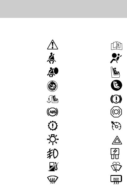
These are some of the symbols you may see on your vehicle.
Vehicle Symbol Glossary |
||
Safety Alert |
See Owner’s Guide |
|
Fasten Safety Belt |
Air Bag-Front |
|
Air Bag-Side |
Child Seat |
|
Child Seat Installation |
Child Seat Lower |
|
Warning |
Anchor |
|
Child Seat Tether |
Brake System |
|
Anchor |
||
|
||
Anti-Lock Brake System |
Brake Fluid - |
|
Non-Petroleum Based |
||
|
||
Powertrain Malfunction |
Speed Control |
|
Master Lighting Switch |
Hazard Warning Flasher |
|
Fog Lamps-Front |
Fuse Compartment |
|
Fuel Pump Reset |
Windshield Wash/Wipe |
|
Windshield |
Rear Window |
|
Defrost/Demist |
Defrost/Demist |
|
8
Introduction
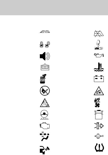
Vehicle Symbol Glossary
Power Windows |
Power Window Lockout |
|
Front/Rear |
||
|
||
Child Safety Door |
Interior Luggage |
|
Compartment Release |
||
Lock/Unlock |
||
Symbol |
||
|
||
Panic Alarm |
Engine Oil |
|
Engine Coolant |
Engine Coolant |
|
Temperature |
||
|
||
Do Not Open When Hot |
Battery |
|
Avoid Smoking, Flames, |
Battery Acid |
|
or Sparks |
||
|
||
Explosive Gas |
Fan Warning |
|
Power Steering Fluid |
Maintain Correct Fluid |
|
Level |
||
|
||
Emission System |
Engine Air Filter |
|
Passenger Compartment |
Jack |
|
Air Filter |
||
|
||
Check fuel cap |
Low tire warning |
MAX
MIN
9

Instrument Cluster
WARNING LIGHTS AND CHIMES
Warning lights and gauges can alert you to a vehicle condition that may become serious enough to cause expensive repairs. A warning light may illuminate when a problem exists with one of your vehicle’s functions.
Many lights will illuminate when you start your vehicle to make sure the bulb works. If any light remains on after starting the vehicle, have the respective system inspected immediately.
Emission system/Check engine:
The Check Engine indicator light illuminates when the ignition is first turned to the ON position to check
the bulb. Solid illumination after the engine is started indicates the On Board Diagnostics System (OBD-II) has detected a malfunction. Refer to
On board diagnostics (OBD-II) in the Maintenance and Specifications chapter. If the light is blinking, engine misfire is occurring which could damage your catalytic converter. Drive in a moderate fashion (avoid heavy acceleration and deceleration) and have your vehicle serviced immediately.
Under engine misfire conditions, excessive exhaust temperatures could damage the catalytic converter, the fuel system, interior
floor coverings or other vehicle components, possibly causing a fire.
Check fuel cap: Illuminates when |
CHECK |
the fuel cap may not be properly |
FUEL |
installed. Continued driving with |
|
this light on may cause the Emission |
CAP |
system/Check engine warning light |
|
to come on. Refer to Fuel Filler Cap in the Maintenance and Specifications chapter.
10
Instrument Cluster
Brake system warning light: To |
BRAKE |
|
confirm the brake system warning |
||
light is functional, it will |
! |
P |
momentarily illuminate when the |
||
ignition is turned to the ON position
when the engine is not running, or in a position between ON and START, or by applying the parking brake when the ignition is turned to the ON position. If the brake system warning light does not illuminate at this time, seek service immediately from your dealership. Illumination after releasing the parking brake indicates low brake fluid level and the brake system should be inspected immediately by your servicing dealership.
Driving a vehicle with the brake system warning light on is dangerous. A significant decrease in braking performance may
occur. It will take you longer to stop the vehicle. Have the vehicle checked by your dealer immediately.
Anti-lock brake system: If the
ABS light stays illuminated or ABS continues to flash, a malfunction has
been detected, have the system serviced immediately. Normal
braking is still functional unless the brake warning light also is illuminated.
Air bag readiness: If this light fails to illuminate when ignition is turned to ON, continues to flash or remains on, have the system serviced
immediately. A chime will also sound when a malfunction in the supplemental restraint system has been detected.
Safety belt: Reminds you to fasten your safety belt. A chime will also sound to remind you to fasten your safety belt.
Charging system: Illuminates when the battery is not charging properly.
11
Instrument Cluster
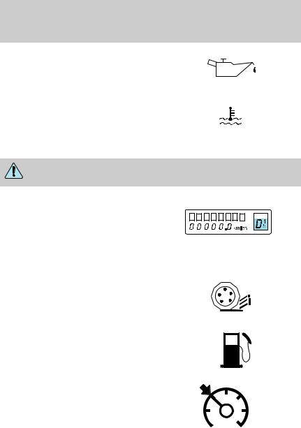
Engine oil pressure: Illuminates when the oil pressure falls below the normal range, refer to Engine oil in the Maintenance and Specifications chapter.
Engine coolant temperature:
Illuminates when the engine coolant temperature is high. Stop the
vehicle as soon as possible, switch off the engine and let cool. Refer to
Engine coolant in the Maintenance and Specifications chapter.
Never remove the coolant reservoir cap while the engine is running or hot.
Transmission PRNDL indicator:
Displays the gearshift positions. If an “E” character is displayed or flashing, this indicates a
transmission malfunction, contact your dealer immediately. Operating the transmission with the “E” character illuminated may cause additional damage to the transmission.
Traction Control active:
Illuminates when the Traction Control is active. If the light remains on, have the system
serviced immediately, refer to the Driving chapter for more information.
Low fuel: Illuminates when the fuel level in the fuel tank is at or near empty (refer to Fuel gauge in this chapter).
Speed control: Illuminates when the speed control is activated. Turns off when the speed control system is deactivated.
12
Instrument Cluster
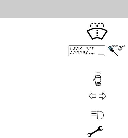
Low washer fluid: Illuminates when the windshield washer fluid is low.
Bulb warning: A text message indicates when one of the exterior
front turn lamps or rear brake/turn/tail lamps bulb has
burned out. Depress the RESET control to return to the Trip odometer display.
Door ajar: Illuminates when the ignition is in the ON position and any door or trunk is open.
Turn signal: Illuminates when the left or right turn signal or the hazard lights are turned on. If the
indicators flash faster, check for a burned out bulb.
High beams: Illuminates when the high beam headlamps are turned on.
Electronic throttle control:
Illuminates when the engine has defaulted to a ’limp-home’ operation. Report the fault to a dealer at the earliest opportunity.
Key-in-ignition warning chime: Sounds when the key is left in the ignition in the OFF/LOCK or ACCESSORY position and the driver’s door is opened.
Headlamps on warning chime: Sounds when the headlamps or parking lamps are on, the ignition is off (the key is not in the ignition) and the driver’s door is opened.
13

Instrument Cluster
GAUGES
Speedometer: Indicates the current vehicle speed.
Engine coolant temperature gauge: Indicates engine coolant temperature. At normal operating temperature, the needle will be in
the normal range (between “H” and
“C”). If it enters the red section, the engine is overheating. Stop
the vehicle as soon as safely
possible, switch off the engine and let the engine cool.
Never remove the coolant reservoir cap while the engine is running or hot.
14
Instrument Cluster
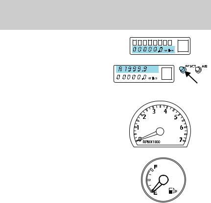
Odometer: Registers the total miles (kilometers) of the vehicle.
Trip odometer: Registers the miles
(kilometers) of individual journeys.
To reset, depress the RESET control. To switch the display from
Trip A to the Trip B, depress the A/B control.
Tachometer: Indicates the engine speed in revolutions per minute. Driving with your tachometer pointer continuously at the top of the scale may damage the engine.
Fuel gauge: Indicates approximately how much fuel is left in the fuel tank (when the ignition is in the ON position). The fuel gauge may vary slightly when the vehicle is in motion or on a grade.
Refer to Filling the tank in the Maintenance and Specifications chapter for more information.
15

Entertainment Systems
AUDIOPHILE SATELLITE READY AM/FM STEREO IN-DASH SIX CD RADIO
1. Seek: Press and release SEEK  /
/  for previous/next strong station or track.
2. Rewind: In CD mode, press until desired selection is reached.
Fast forward: In CD mode, press until desired selection is reached.
TEXT: TEXT is only available when equipped with Satellite radio. Your Audiophile radio comes equipped with Satellite ready capability. The kit to enable Satellite reception is available through your Ford dealer.
Detailed Satellite instructions are included with the dealer installed kit.
Dealer installed satellite kit available only in the continental United States.
3. DSP (Digital Signal Processing): Press DSP to access the Ambiance menu. Ambiance gives the feeling of “being there” to your
music, creating increased clarity as well as an open and spacious feel to the music. Press SEL to engage/disengage. Turn the volume control to increase/decrease the level of ambiance.
16

Entertainment Systems
Occupancy: Press DSP again to change the occupancy mode to optimize sound for ALL SEATS, DRIVER SEAT or TOP DOWN. Press SEL to scroll through settings.
4. Mute: Press to MUTE playing media; press again to return to playing media
5. Eject: Press to eject a CD. Press and hold to eject all loaded discs.
6. Bass: Press BASS; then press SEL  /
/  to decrease/increase the bass output.
Treble: Press TREB; then press SEL  /
/  to decrease/increase the treble output.
7. Select: Use with Bass, Treble, Balance and Fade controls to adjust levels and set the clock.
8. Balance: Press BAL; then press SEL  /
/  to shift sound to the left/right speakers.
Fade: Press FADE; then press SEL  /
/  to shift sound to the rear/front speakers.
9. Menu: Press MENU and SEL to access clock mode, RDS on/off, Traffic announcement mode, Program type mode, and Shuffle mode.
The Federal Communications Commission (FCC) and the Canadian Radio and Telecommunications Commission (CRTC) recommend that FM radio broadcasters use RDS technology to transmit information. FM radio stations are independently operated and individually elect to use RDS technology to transmit station ID and program type as desired.
17
Entertainment Systems
Traffic: Allows you to hear traffic broadcasts. With the feature ON, press SEEK or SCAN to find a station broadcasting a traffic report (if it is broadcasting RDS data).Traffic information is not available in most U.S. markets.
FIND Program type: Allows you to search RDS-equipped stations for a certain category of music format: Classic, Country, Info, Jazz, Oldies, R&B, Religious, Rock, Soft, Top 40.
Show TYPE: Displays the station’s call letters and format.
Shuffle: With a CD playing, press to play tracks in a random order. Press MENU until SHUF appears in the display. Use SEL to select SHUF DISC, SHUF TRAC or SHUF OFF.
Compression: With a CD playing, compression brings soft and loud CD passages together for a more consistent listening level. Press MENU until compression status is displayed. Press the SEL control to enable the compression feature when COMP OFF is displayed. Press the SEL control again to disable the feature when COMP ON is displayed.
Setting the clock: Press MENU until SELECT HOUR or SELECT MINS is displayed. Use SEL to manually increase ( ) or decrease (
 ) the hours/minutes. Press MENU again to disengage clock mode.
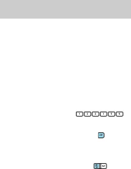
10. Memory presets: To set a station: Select frequency band AM/FM; tune to a station, press and hold a preset button until sound returns.
11. SAT (if equipped): Your Audiophile radio comes equipped with Satellite Ready capability. The
kit to enable the Satellite reception is available through your Ford dealer. Detailed satellite instructions are included with the dealer installed kit.
Dealer installed satellite kit available only in the continental United States.
12. AM/FM: Press to select AM/FM frequency band.
Autoset: Allows you to set the
strongest local radio stations without losing your original manually set preset stations for AM/FM1/FM2 . Press and momentarily hold AM/FM. AUTOSET will flash on the display. When the six strongest stations are filled, the station stored in preset 1 will begin playing. If there are less than six strong stations, the system will store the last one in the remaining presets. Press again to disengage.
18

Entertainment Systems
13. Power/volume: Press to turn ON/OFF; turn to increase or decrease volume levels.
Speed sensitive volume: Radio volume changes automatically and slightly with vehicle speed to
compensate for road and wind noise. Recommended level is 1–3. Level 0 turns the feature off and level 7 is the maximum setting.
Press and hold the volume control for five seconds. Then press SEL to increase ( ) or decrease (
 ) the volume setting. The level will appear in the display.
14. Load: Press to load a CD. Press and hold to load up to six discs.
15. CD AUX: Press to access CD or AUX mode.
CD units are designed to play
commercially pressed 4.75 in (12 cm) audio compact discs only. Due to technical incompatibility, certain recordable and re-recordable compact discs may not function correctly when used in Ford CD players. Irregular shaped CDs, CDs with a scratch protection film attached, and CDs with homemade paper (adhesive) labels should not be inserted into the CD player. The label may peel and cause the CD to become jammed. It is recommended that homemade CDs be identified with permanent felt tip marker rather than adhesive labels. Ballpoint pens may damage CDs. Please contact your dealer for further information.
16. Scan: Press SCAN to hear a brief sampling of radio stations or CD tracks. Press again to stop.
17. Disc/Tune: Press  or
or  to
to
manually tune down/up the radio frequency band, or to listen to the previous/next track on the CD.
CAT: CAT is only available when equipped with Satellite Radio. Your Audiophile radio comes equipped with Satellite ready capability. The kit to enable Satellite reception is available through your Ford dealer. Detailed Satellite instructions are included with the dealer installed kit.
Dealer installed satellite kit available only in the continental United States.
19

Entertainment Systems
For information regarding SIRIUS Satellite Radio, please call toll-free 888-539-SIRIUS (888-539-7474) or visit the SIRIUS website at www.siriusradio.com
RADIO FREQUENCIES
AM and FM frequencies are established by the Federal Communications Commission (FCC) and the Canadian Radio and Telecommunications Commission (CRTC). Those frequencies are:
AM - 530, 540–1700, 1710 kHz
FM87.7, 87.9–107.7, 107.9 MHz
RADIO RECEPTION FACTORS
There are three factors that can effect radio reception:
•Distance/strength: The further you travel from an FM station, the weaker the signal and the weaker the reception.
•Terrain: Hills, mountains, tall buildings, power lines, electric fences, traffic lights and thunderstorms can interfere with your reception.
•Station overload: When you pass a broadcast tower, a stronger signal may overtake a weaker one and play while the weak station frequency is displayed.
CD/CD PLAYER CARE
Do:
•Handle discs by their edges only. Never touch the playing surface.
•Inspect discs before playing. Clean only with an approved CD cleaner and wipe from the center out.
Don’t:
•Expose discs to direct sunlight or heat sources for extended periods of time.
•Insert more than one disc into each slot of the CD changer magazine.
•Clean using a circular motion.
20
Entertainment Systems
CD units are designed to play commercially pressed 12 cm (4.75 in) audio compact discs only. Due to technical incompatibility, certain recordable and re-recordable compact discs may not function correctly when used in Ford CD players. Irregular shaped CDs, CDs with a scratch protection film attached, and CDs with homemade paper (adhesive) labels should not be inserted into the CD player. The label may peel and cause the CD to become jammed. It is recommended that homemade CDs be identified with permanent felt tip marker rather than adhesive labels. Ball point pens may damage CDs. Please contact your dealer for further information.
AUDIO SYSTEM WARRANTY AND SERVICE
Refer to the Warranty Guide for audio system warranty information. If service is necessary, see your dealer or qualified technician.
21
Climate Controls
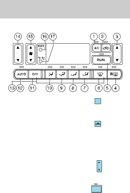
DUAL ELECTRONIC AUTOMATIC TEMPERATURE CONTROL (DEATC) SYSTEM
1. A/C control: Press to turn on |
A/C |
and manually control the air |
|
conditioning. Press again to |
|
disengage. Press AUTO for the system to automatically control the temperature.
2. Recirculation control: Press to engage/disengage. Used to manually
enable or disable recirculated air
operation. When activated, recirculates air in the cabin thereby reducing the amount of time to cool down the interior of the vehicle. May also help reduce undesired odors from reaching the interior of the vehicle. Will work in all modes except defrost. Recirculation turns off automatically when floor, floor/defrost or defrost mode is selected. To reduce humidity inside the vehicle, turn recirculation off.
3. Passenger side temperature control: Press to engage the dual
zone feature of the DEATC system. Allows the passenger to choose and
control a different temperature than the driver, if desired.
4. Rear defroster: Press to defrost the rear window. Refer to Rear Window defroster for more information.
R
22
Climate Controls
5. DUAL zone selector: Press to toggle the system between single zone and dual zone control.
DUAL
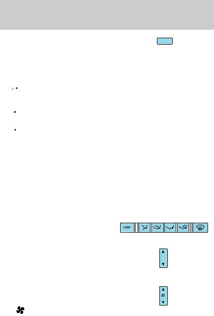
6. (Defrost): Distributes outside air through the windshield defroster ducts and the demister outlets. Can be used to clear ice or fog from the windshield. The system will automatically provide outside air to reduce window fogging.
7. : Distributes air through the windshield defroster ducts, demister outlets, and the floor ducts. The system will automatically provide outside air to reduce window fogging.
8. : Distributes air through the floor ducts. The system will automatically provide outside air to reduce window fogging.
9. : Distributes air through the instrument panel, and the floor ducts.
10. : Distributes air through the instrument panel.
11. |
OFF: Outside air is shut out and |
OFF |
the fan will not operate. |
|
|
|
||
12. |
Auto: To engage automatic |
|
AUTO |
||
temperature control, press AUTO |
|
|
|
||
and select the desired temperature |
|
|
using the temperature control. The system will automatically determine fan speed, airflow location, AC on or off, and outside or recirculated air, to heat or cool the vehicle to reach the desired temperature.
13. Manual override controls:
Allows you to manually select where airflow is directed. To return to full automatic control, press AUTO.
14. Driver’s side temperature control: Controls the temperature on the driver side of the vehicle in dual zone and controls the
temperature of the entire vehicle in single zone.
15. Fan Speed: Press to manually increase/decrease fan speed. In manual mode, the display will show  with a bar graph to
indicate fan speed. Fan speed can be manually adjusted in AUTO mode. To allow the system to automatically control fan speed, press AUTO.
23

Climate Controls
16. EXT control: Press to display |
EXT |
the outside air temperature. Press |
|
again to return to interior |
|
temperature. Exterior readings are most accurate when the vehicle is moving.
17. Temperature conversion: |
F C |
Press to toggle between Fahrenheit |
|
and Celsius temperature on the
DEATC display only. The set point temperatures in Celsius will be displayed in half-degree increments.
OPERATING TIPS
•To reduce fog build up on the windshield during humid weather, place the air flow selector in the  position.
•To reduce humidity build up inside the vehicle:
Do not drive with the air flow selector in the OFF position. Do not drive with recirculation engaged.
•In order to allow the vehicle to “breathe” using the outside air inlet vents, do not leave the air flow selector in the OFF position when the vehicle is parked.
•Remove any snow, ice or leaves from the air intake area at the base of the windshield.
•With the ignition in the OFF position after operating the vehicle, some vehicle sounds related to the climate control system may be heard.
•Approximately two minutes after key off, the air distribution doors may adjust their positions as part of the normal operating process.
•Demisters, located at the far left and right sides of the dash, usually blow out a small amount of airflow in order to reduce side window fogging.
•Outboard panel registers, located at the left and right sides of the dash, blow out a small amount of airflow when in Floor, Floor/Defrost, and Defrost modes. This also reduces side window fogging.
24
Climate Controls
• Do not place items over the climate temperature sensor grid. This may cause improper operation of the system.
To aid in side window defogging/demisting in cold weather:
1.Select  .
.
2.Ensure that recirculation is disengaged.
3.Set the temperature control to full heat.
4.Set the fan to the highest speed.
5.Direct the outer instrument panel vents towards the side windows.
To increase airflow to the outer instrument panel vents, close the vents located in the middle of the instrument panel.
Do not place objects on top of the instrument panel as these objects may become projectiles in a collision or sudden stop.
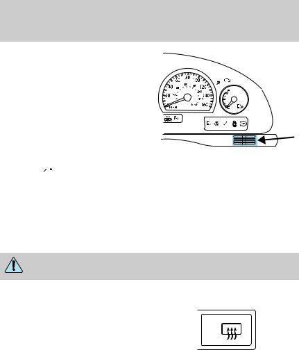
REAR WINDOW DEFROSTER 
Press the rear window defroster control to clear the rear window of
thin ice or fog. The light above the R control will illuminate to indicate
that the rear defroster is operating.
The ignition must be in the RUN position and the engine running in order to operate the rear window defroster.
The rear window defroster turns off automatically after a predetermined amount of time, if a low battery condition is detected, or if the ignition is turned to the OFF position. To manually turn off the rear window defroster at any time, press the control again.
Do not use razor blades or other sharp objects to clean the inside of the rear window or to remove decals from the inside of the rear window. This may cause damage to the heated grid lines and will not be covered by your warranty.
25

Climate Controls
CABIN AIR FILTER
Your vehicle is equipped with a cabin air filter. The particulate air filtration system is designed to reduce the concentration of airborne particles such as dust, spores and pollen in the air being supplied to the interior of the vehicle. The particulate filtration system gives the following benefits to customers:
•Improves the customer’s driving comfort by reducing particle concentration
•Improves the interior compartment cleanliness
•Protects the climate control components from particle deposits
The filter is located just in front of the windshield under the cowl grille on the passenger side of the vehicle.
For more information, or to replace the filter, see your Ford or Lincoln Mercury dealer.
26
Lights
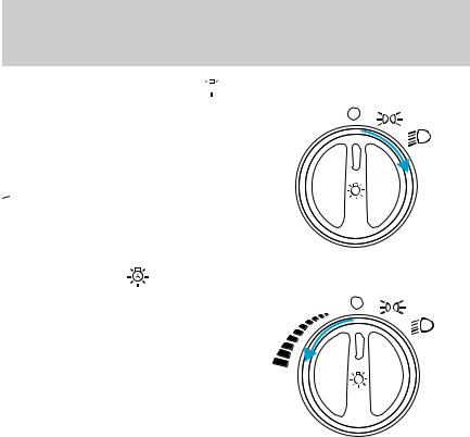
MASTER LIGHTING SWITCH 


 Turns the lamps off.

 Turns on the parking lamps, instrument panel lamps, license plate lamps and tail lamps.
 Turns on the headlamps, parking lamps, instrument panel lamps, license plate lamps and tail lamps.
Autolamp control |
|
|
The autolamp system provides light |
|
|
sensitive automatic on-off control of |
AUTO |
|
the exterior lights normally |
||
|
||
controlled by the master lighting |
|
|
switch. |
|
The autolamp system also keeps the lights on for a preselected period of time after the ignition switch is turned to OFF.
•To turn autolamps on, rotate the
control counterclockwise. The preselected time lapse is adjustable up to approximately three minutes by continuing to rotate the control counterclockwise.
•To turn autolamps off, rotate the control clockwise to OFF.
Note: The instrument panel lamps will only turn on if the autolamp control has determined it is night.
Daytime running lamps (DRL) (Canada Only)
Turns the lowbeam headlamps on with a reduced output.
To activate with automatic transmission:
•the ignition must be in the RUN position;
•the headlamp control is in the OFF position, Parking lamps position, or Autolamp position when the autolamp function has not turned on the headlamps (daytime); and
•the transmission is out of Park.
27
Lights
Always remember to turn on your headlamps at dusk or during inclement weather. The Daytime Running Light (DRL) System
does not activate your tail lamps and generally may not provide adequate lighting during these conditions. Failure to activate your headlamps under these conditions may result in a collision.
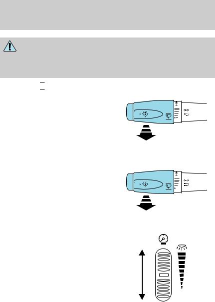
High beams 

Pull toward you until control stops to activate. Repeat to deactivate.
Flash to pass
Pull toward you slightly to activate and release to deactivate.
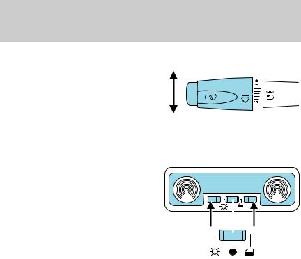
PANEL DIMMER CONTROL
Use to adjust the brightness of the instrument panel during parklamp, headlamp and autolamp operation.
• Rotate up to brighten.
• Rotate down to dim.
• Rotate fully up to turn on the floor and dome lights.
Note: When the headlamp switch is in the autolamp position, the panel dimmer control is only active when the autolamp has determined that it is night.
28

Lights
The dome light will only go on when the dome light switch is in the delay or ON position.
HEADLAMP VERTICAL AIM ADJUSTMENT
1. Park the vehicle directly in front of a wall or screen on a level surface, approximately 25 feet (7.6 meters) away.
• (1) 8 feet (2.4 meters)
• (2) Center height of lamp to ground
• (3) 25 feet (7.6 meters)
• (4) Horizontal reference line
2. Measure the height from the center of your headlamp to the
ground and mark an 8 foot (2.4 meter) horizontal reference line on
the vertical wall or screen at this
height (a piece of masking tape works well). The center of the lamp is marked by a 3.0 mm circle on the headlamp lens.
3.Turn on the low beam headlamps to illuminate the wall or screen and open the hood.
4.On the wall or screen you will
observe a light pattern with flat edges at the top of the beam pattern. If the flat edges are not at the horizontal reference line, the beam will need to be adjusted.
To see a clearer light pattern for adjusting, you may want to block the light from one headlamp while adjusting the other.
5.Locate the vertical adjuster on each headlamp, then use a 6 mm Allen wrench or screwdriver to adjust the headlamp up or down.
6.HORIZONTAL AIM IS NOT REQUIRED FOR THIS VEHICLE AND IS NON-ADJUSTABLE.
7.Close the hood and turn off the lamps.
29
Lights
TURN SIGNAL CONTROL 

• Push down to activate the left turn signal.
• Push up to activate the right turn signal.
INTERIOR LAMPS
Reading and dome lamps
The reading lamps are located in the header trim panel. Press the control next to the reading lamp to activate it.
The reading lamp assembly also contains an overhead dome lamp.
This lamp is controlled by the center (OFF) control on the
assembly. The dome lamp will stay on if the control is moved to the
driver side (ON) position. When the
control is in the passenger side (delay) position, the lamp will only come on when a door is opened, or if the panel dimmer control is fully rotated up. If the control is moved to the center position, the lamp will not come on at all.
BULB REPLACEMENT
Headlamp Condensation
The headlamps are vented to equalize pressure. When moist air enters the headlamp(s) through the vents, there is a possibility that condensation can occur. This condensation is normal and will clear within 45 minutes of headlamp operation.
Replacing exterior bulbs
Check the operation of all of the bulbs periodically.
30
Loading...