


501-00-1 |
Body System — General Information |
501-00-1 |
DESCRIPTION AND OPERATION
Body Sealer Types And Applications
Clear Silicone Rubber TA-32
Clear Silicone Rubber TA-32 or equivalent meeting Ford specification ESB-M4G92-A is used for sealing water leaks, noise concerns, remounting trim, and repairing torn weatherstripping.
Caulking Cord
3M Strip Caulk-Black 051135-08578 or equivalent meeting Ford specification WSB-M4G32-C:
•is a heavy-bodied, plastic base with a filler.
•is commonly known as perma-gum.
•is used on spot-welds holes, around moulding clips, and between surfaces not sealed with a gasket.
Weatherstrip Adhesive
Trim and Weatherstrip Adhesive TA-14 is a quick drying, strong adhesive designed to hold weatherstripping onto all body panels and surrounding metal.
Silicone Spray Lubricant
Silicone Spray Lubricant XL-6 meeting Ford specification ESR-M13P4-A:
•is used to keep the door and the window weatherstrip pliable and soft.
•should be applied to the weatherstrip at every lubrication period.
•makes the door easier to close.
•retards weatherstrip squeaks.
•retards weatherstrip wear.
•helps retain door window alignment by reducing friction between the glass frame and the rubber weatherstrip.
•should not be used prior to painting.
Copyright ♥ 2006, Ford Motor Company |
2007 Mustang, Mustang GT 8/2006 |
Last updated: 6/19/2006 |

501-00-1 |
Body System — General Information |
501-00-1 |
DESCRIPTION AND OPERATION
Body
Body and Sheet Metal
The body:
•is a unibody open cowl structure.
•is constructed of a lightweight, all-steel material with a removable, bolted hood, front fenders, doors, and luggage compartment lid.
Copyright ♥ 2006, Ford Motor Company |
2007 Mustang, Mustang GT 8/2006 |
Last updated: 6/19/2006 |

501-00-1 |
Body System — General Information |
501-00-1 |
DESCRIPTION AND OPERATION
Insulation
Insulation is comprised of urethane, PVC, and recycled felt. Insulation is installed:
•under the roof panel.
•above and below the instrument panel.
•on the cowl sides.
•over the front and rear floor areas.
•on a coupe, in the B and C-pillar sections.
•under the hood.
Copyright ♥ 2006, Ford Motor Company |
2007 Mustang, Mustang GT 8/2006 |
Last updated: 6/19/2006 |

501-00-1 |
Body System — General Information |
501-00-1 |
DIAGNOSIS AND TESTING
Body System
Material
Item |
Specification |
Silicone Gasket and |
WSE-M4G323-A4 |
Sealant |
|
TA-30 |
|
Inspection and Verification
Leaks
NOTE: Trim reveals the location of most leaks.
1.Remove any trim or carpet in the general area of the leak.
2.Road test or water test the vehicle.
3.Inspect for a dust pattern around the area in question. Inspect for water paths near and above the area in question.
Symptom Chart
Symptom Chart
4.Some leaks can be located by placing bright light under the vehicle, removing any necessary trim or carpet, and inspecting the interior of the body at joints and weld lines.
Noise
Wind noise, rattles, and their sources are detected by driving the vehicle at highway speeds. The vehicle should be driven in 4 different directions with all of the windows closed, the radio off, the blower motor off, and all of the ventilation ducts open.
Most wind noise leaks occur at the door and window seals or at the sheet metal joints in the door or the door opening.
Condition |
|
Possible Sources |
Action |
• Dust and water leaks |
• |
Body sealer missing |
• REMOVE the trim panel. |
|
• Opening in the weldings or |
CHECK for leaks and SEAL |
|
|
• |
body joints |
with the appropriate sealer. |
|
Components not fully |
ROAD TEST or WATER |
|
|
• |
installed |
TEST for leaks. RECHECK |
|
Components missing |
for leaks; use light under the |
|
|
• |
Components damaged |
vehicle with the trim |
|
|
|
removed. CHECK the interior |
|
|
|
of the body at the joints and |
|
|
|
weld lines. |
• Dust/water leaks at the floor |
• |
Missing or damaged plugs |
• CHECK the plugs for proper |
pan and grommets |
|
and/or grommets |
installation. REPLACE if |
|
|
|
necessary. |
• Door drain holes collecting |
• |
Holes clogged with mud or |
• CLEAN the drain holes of |
water |
|
road tar |
dirt and foreign material. |
|
|
|
CHECK the drain holes |
|
|
|
regularly. TEST the system |
|
|
|
for normal operation. |
• Wind noise, air entering the |
• |
Leaks at the door and |
• SEAL leaks with Silicone |
vehicle through small holes in |
|
window seals or sheet metal |
Gasket and Sealant. ROAD |
the body |
|
joints in the doors or door |
TEST. |
|
|
openings |
|
Copyright ♥ 2006, Ford Motor Company |
2007 Mustang, Mustang GT 8/2006 |
Last updated: 6/19/2006 |

501-00-2 |
Body System — General Information |
|
501-00-2 |
|||||
|
|
|
|
|
||||
DIAGNOSIS AND TESTING (Continued) |
|
|
|
|||||
Symptom Chart (Continued) |
|
|
|
|
|
|
|
|
|
|
|
|
|
|
|
|
|
|
Condition |
|
|
Possible Sources |
|
|
Action |
|
• Rattles |
|
• |
Loose objects in the wells, |
|
• |
CHECK the doors by |
||
|
|
|
• |
pillars, and quarter panels |
|
|
carefully STRIKING the |
|
|
|
|
Misalignment (if tightening |
|
|
underside of the door with a |
||
|
|
|
|
bolts does not eliminate |
|
|
rubber mallet. LISTEN for |
|
|
|
|
• |
rattle) |
|
|
loose objects in the door. |
|
|
|
|
Weatherstripping and/or |
|
|
REPAIR. TIGHTEN the body |
||
|
|
|
|
anti-squeak material |
|
|
bolts and screws. |
|
|
|
|
|
|
|
• ADJUST the alignment of the |
||
|
|
|
|
|
|
|
doors or panels. REFER to |
|
|
|
|
|
|
|
• |
Section 501-03. |
|
|
|
|
|
|
|
APPLY additional sealer. |
||
|
|
|
|
|
|
|
INSTALL in the proper |
|
|
|
|
|
|
|
|
location to eliminate rattle. |
|
|
|
|
|
|
|
|
|
|
2007 Mustang, Mustang GT 8/2006

501-00-1 |
Body System — General Information |
501-00-1 |
SPECIFICATIONS
General Specifications
Item |
Specification |
|
|
Adhesives |
|
|
|
Trim and Weatherstrip |
— |
Adhesive TA-14 |
|
|
|
Clear Silicone Rubber |
ESB-M4G92-A |
TA-32 |
|
|
|
Lubricants |
|
|
|
General Specifications (Continued)
Item |
Specification |
|
|
Silicone Spray Lubricant |
ESR-M13P4-A |
XL-6 |
|
|
|
Sealers |
|
|
|
3M Strip Caulk-Black |
WSB-M4G32-C |
051135-08578 |
|
|
|
Silicone Gasket and |
WSE-M4G323-A4 |
Sealant TA-30 |
|
|
|
Copyright ♥ 2006, Ford Motor Company |
2007 Mustang, Mustang GT 8/2006 |
Last updated: 6/19/2006 |

501-02-1 |
Front End Body Panels |
501-02-1 |
DESCRIPTION AND OPERATION
Front End Body Panels
The front end body panel components consist of the following:
•Air deflectors
•Cowl vent screens
•Fenders
•Fender splash shields
•Hood
•Hood hinges
Copyright ♥ 2006, Ford Motor Company |
2007 Mustang, Mustang GT 8/2006 |
Last updated: 6/19/2006 |

501-02-1 |
Front End Body Panels |
501-02-1 |
REMOVAL AND INSTALLATION
Cowl Vent Screen
Item |
Part Number |
Description |
1 |
17D515 |
Wiper pivot arm nut covers |
|
|
(2 required) |
2 |
W706109 |
Wiper pivot arm nuts (2 |
|
|
required) |
3 |
175261/17527 |
Wiper pivot arms |
|
|
|
4 |
N804837 |
Cowl vent screen pin-type |
|
|
retainers (4 required) |
5 |
G046000094 |
RH cowl vent screen |
6 |
G046000093 |
LH cowl vent screen |
1.Remove the 2 wiper pivot arms. For additional information, refer to Section 501-16.
2.Remove the 4 cowl vent screen pin-type retainers.
3.NOTE: The RH cowl vent screen overlaps the LH cowl vent screen and must be removed first.
Remove the RH and LH cowl vent screens.
4.To install, reverse the removal procedure.
Copyright ♥ 2006, Ford Motor Company |
2007 Mustang, Mustang GT 8/2006 |
Last updated: 6/19/2006 |
501-02-1 |
Front End Body Panels |
501-02-1 |
REMOVAL AND INSTALLATION
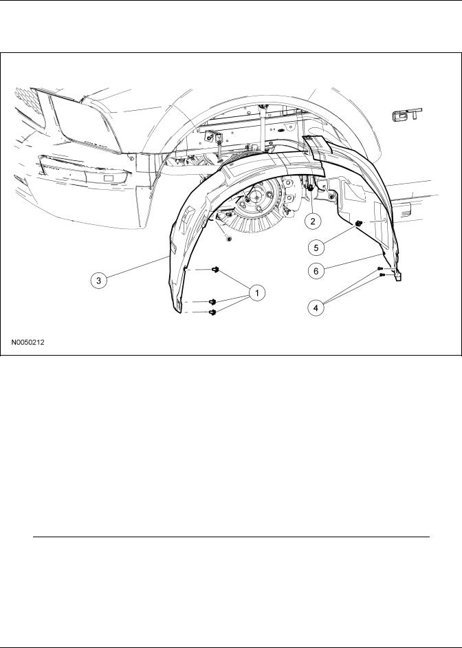
Fender Splash Shield
Item |
Part Number |
Description |
1 |
W706805 |
Fender splash shield screws |
|
|
(3 required) |
2 |
16K194 |
Fender splash shield pin-type |
|
|
retainer (front) (5 required) |
3 |
16B568 |
Fender splash shield (front) |
|
|
|
4 |
W709176 |
Rocker panel pin-type |
|
|
retainers (2 required) |
5 |
16K194 |
Fender splash shield pin-type |
|
|
retainers (rear) (2 required) |
6 |
16B568 |
Fender splash shield (rear) |
Removal and Installation
1.Remove the 3 front fender splash shield screws.
2.Remove the 5 pin-type retainers and the front fender splash shield.
3.Remove the 2 pin-type retainers and position the rocker panel aside.
4.Remove the 2 pin-type retainers and the rear fender splash shield.
5.To install, reverse the removal procedure.
Copyright ♥ 2006, Ford Motor Company |
2007 Mustang, Mustang GT 8/2006 |
Last updated: 6/19/2006 |

501-02-1 |
Front End Body Panels |
501-02-1 |
REMOVAL AND INSTALLATION
Fender
Item |
Part Number |
Description |
1 |
39001B |
Rocker panel pin-type |
|
|
retainers (4 required) |
2 |
6310155 |
Rocker panel |
3 |
W505421 |
Fender bolts (lower) (2 |
|
|
required) |
4 |
W505421 |
Fender bolt |
|
|
|
5 |
W505421 |
Fender support nut |
|
|
|
6 |
W505421 |
Fender bolts (top) (4 |
|
|
required) |
7 |
16015 |
Fender |
Removal and Installation
Both fenders
1.Remove the front bumper cover. For additional information, refer to Section 501-19.
2.Remove the fender splash shield. For additional information, refer to Fender Splash Shield in this section.
3.Remove the 4 front rocker panel pin-type retainers and position the rocker panel aside.
4.Remove the 2 lower fender bolts.
• To install, tighten to 11 Nm (8 lb-ft).
5.Remove the fender bolt.
Copyright ♥ 2006, Ford Motor Company |
2007 Mustang, Mustang GT 8/2006 |
Last updated: 6/19/2006 |
501-02-2 |
Front End Body Panels |
501-02-2 |
REMOVAL AND INSTALLATION (Continued)
6.Remove the fender support nut through the door opening.
• To install, tighten to 11 Nm (8 lb-ft).
Right fender
7.Disconnect the antenna lead-in cable. For additional information, refer to Section 415-02.
8.Disconnect the hood ajar switch.
Both fenders
9.Remove the 4 top fender bolts and the fender.
• To install, tighten to 11 Nm (8 lb-ft).
10.To install, reverse the removal procedure.
2007 Mustang, Mustang GT 8/2006

501-02-1 |
Front End Body Panels |
501-02-1 |
SPECIFICATIONS
Torque Specifications
Description |
Nm |
lb-ft |
|
|
|
Wiper pivot arm nuts |
28 |
21 |
|
|
|
Torque Specifications (Continued)
Description |
Nm |
lb-ft |
|
|
|
Fender bolts/nuts |
11 |
8 |
|
|
|
Copyright ♥ 2006, Ford Motor Company |
2007 Mustang, Mustang GT 8/2006 |
Last updated: 6/19/2006 |

501-03-1 |
Body Closures |
501-03-1 |
DESCRIPTION AND OPERATION
Body Closures
The body closures consist of the following components:
•door check arms
•front doors
•front door latch striker plates
•front door hinges
•hood
•hood hinges
•luggage compartment lid
•luggage compartment lid hinges
•luggage compartment lid hydraulic lifts
•luggage compartment lid latch striker
Copyright ♥ 2006, Ford Motor Company |
2007 Mustang, Mustang GT 8/2006 |
Last updated: 6/19/2006 |

501-03-1 |
Body Closures |
501-03-1 |
GENERAL PROCEDURES
Door Alignment
NOTE: The door should be adjusted for even and parallel fit with the body opening and surrounding panels as well as making sure the anti-chuck pin is not binding on convertible models.
1.Mark the position of the front door hinges to the front door to use as reference points.
2.Loosen the 4 front door hinge-to-front door bolts enough to permit movement.
3.Adjust the front door alignment to specification.
4.NOTE: After aligning the door, verify the door can be closed easily and fits tightly.
Tighten the 4 front door hinge-to-front door bolts.
• Tighten to 30 Nm (22 lb-ft).
Copyright ♥ 2006, Ford Motor Company |
2007 Mustang, Mustang GT 8/2006 |
Last updated: 6/19/2006 |

501-03-1 |
Body Closures |
501-03-1 |
GENERAL PROCEDURES
Hinge Adjustment
1.Remove the fender. For additional information, refer to Section 501-02.
2.Mark the position of the upper and lower front door hinges to the body to use as reference points.
3.Loosen the 2 upper and 2 lower front door hinge-to-body bolts enough to permit movement.
4.Adjust the front door to specification.
5.NOTE: After adjusting the door hinge, verify the door can be closed easily and fits tightly. Tighten the 4 front door hinge-to-body bolts.
• Tighten to 30 Nm (22 lb-ft).
6.Install the fender. For additional information, refer to Section 501-02.
Copyright ♥ 2006, Ford Motor Company |
2007 Mustang, Mustang GT 8/2006 |
Last updated: 6/19/2006 |

501-03-1 |
Body Closures |
501-03-1 |
GENERAL PROCEDURES
Striker Adjustment
NOTE: After adjusting the door latch striker plate, verify the door can be closed easily and fits tightly.
1.Loosen the door latch striker plate bolts.
2.Reposition the door latch striker plate from side to side or up and down as necessary.
3.Tighten the 2 door latch striker plate bolts.
• Tighten to 25 Nm (18 lb-ft).
4.Check the adjustment. Repeat the procedure as necessary.
Copyright ♥ 2006, Ford Motor Company |
2007 Mustang, Mustang GT 8/2006 |
Last updated: 6/19/2006 |
501-03-1 |
Body Closures |
501-03-1 |
REMOVAL AND INSTALLATION
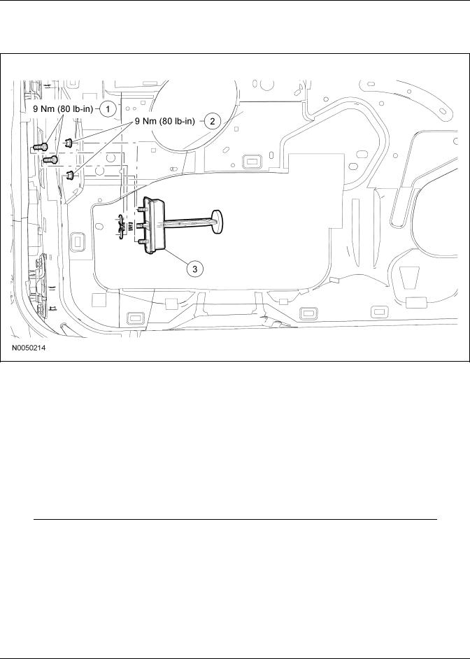
Door Check Arm
Item |
Part Number |
Description |
1 |
56912 |
Door check arm bolts (2 |
|
|
required) |
2 |
W705436 |
Door check arm nuts (2 |
|
|
required) |
3 |
23500 |
Door check arm |
|
|
|
Removal and Installation
1.Remove the front door trim panel. For additional information, refer to Section 501-05.
2.Remove the door check arm bolts.
•To install, tighten to 9 Nm (80 lb-in).
3.Remove the nuts and the door check arm.
•To install, tighten to 9 Nm (80 lb-in).
4.To install, reverse the removal procedure.
Copyright ♥ 2006, Ford Motor Company |
2007 Mustang, Mustang GT 8/2006 |
Last updated: 6/19/2006 |

501-03-1 |
Body Closures |
501-03-1 |
SPECIFICATIONS
General Specifications
Item |
Specification |
|
|
Premium Long Life |
ESA-M1C75-B |
Grease XG-1-C or |
|
XG-1-K (US); CXG-1-C |
|
(Canada) |
|
|
|
Silicone Spray Lubricant |
ESR-M13P4-A |
XL-6 |
|
|
|
Multi-Purpose Grease |
ESB-M1C93-B |
Spray XG-4 and/or XL-5 |
|
|
|
Door clearance: bottom of |
5.0 - 6.0 mm (0.196 - |
the door to the rocker |
0.236 in) parallel top to |
panel |
bottom within 1.0 mm |
|
(0.04 in) |
|
|
Door clearance: between |
4.0 - 5.0 mm (0.157 - |
fender and door |
0.196 in) parallel top to |
|
bottom within 1.0 mm |
|
(0.04 in) |
|
|
Door flushness: door to |
-1.0 - 0.00 mm (-0.04 - |
the front fender |
0.00 in) |
|
|
Torque Specifications
Description |
Nm |
lb-ft |
lb-in |
|
|
|
|
Door check arm bolts |
9 |
— |
80 |
|
|
|
|
Door check arm nuts |
9 |
— |
80 |
|
|
|
|
Door latch striker plate |
25 |
18 |
— |
bolts |
|
|
|
|
|
|
|
Front door |
30 |
22 |
— |
hinge-to-body bolts |
|
|
|
|
|
|
|
Front door |
30 |
22 |
— |
hinge-to-front door |
|
|
|
bolts |
|
|
|
|
|
|
|
Luggage compartment |
23 |
17 |
— |
lid hinge bolts |
|
|
|
|
|
|
|
Luggage compartment |
12 |
9 |
— |
lid hinge nuts |
|
|
|
|
|
|
|
Copyright ♥ 2006, Ford Motor Company |
2007 Mustang, Mustang GT 8/2006 |
Last updated: 6/19/2006 |

501-05-1 |
Interior Trim and Ornamentation |
501-05-1 |
DESCRIPTION AND OPERATION
Interior Trim
The interior trim consists of:
•A-pillar trim panels
•A-pillar lower trim panels
•door trim panels
•coat hooks
•headliner
•header trim panel (convertible)
•upper quarter trim panels (convertible)
•lower quarter trim panels (convertible)
•upper quarter trim panel caps (convertible)
•quarter trim panels
•parcel shelf trim panel
•quarter window trim panels
•door scuff plates
•sun visors
•tether anchor covers (coupe)
Copyright ♥ 2006, Ford Motor Company |
2007 Mustang, Mustang GT 8/2006 |
Last updated: 6/19/2006 |
501-05-1 |
Interior Trim and Ornamentation |
501-05-1 |
REMOVAL AND INSTALLATION
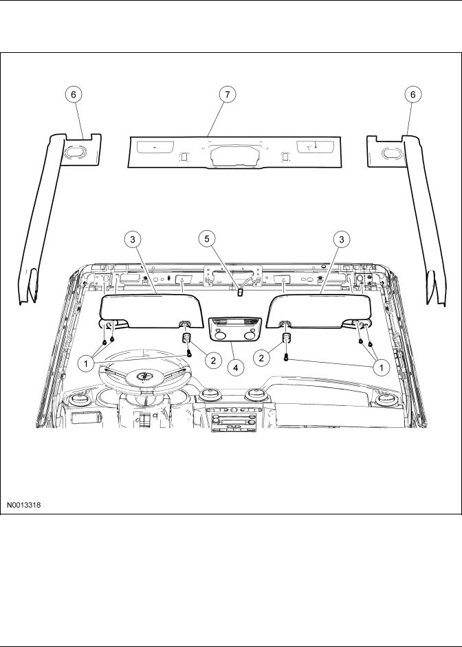
A-Pillar Trim Panel
Item |
Part Number |
Description |
1 |
N806664 |
Sun visor screws/sun visor |
|
|
arm clip screws (6 required) |
2 |
04132 |
Sun visor arm clips (2 |
|
|
required) |
3 |
4104/4105 |
Sun visors (2 required) |
|
|
(RH/LH) |
(Continued) |
|
|
Item |
Part Number |
Description |
4 |
519A58 |
Overhead console |
5 |
— |
Overhead console electrical |
|
|
connector (part of 14A464) |
6 |
030A64 |
A-pillar trim panel (2 |
|
|
required) (RH/LH) |
7 |
51916 |
Header trim panel |
Copyright ♥ 2006, Ford Motor Company |
2007 Mustang, Mustang GT 8/2006 |
Last updated: 6/19/2006 |
501-05-2 |
Interior Trim and Ornamentation |
501-05-2 |
REMOVAL AND INSTALLATION (Continued)
Removal and Installation
NOTE: If removing the header trim panel, remove the 2 A-pillar trim panels.
1.Remove the 2 sun visor srews and the sun visor.
2.Remove the A-pillar trim panel.
3.If necessary, remove the overhead console.
• Disconnect the electrical connector.
4.If necessary, remove the 2 screws and the 2 sun visor arm clips.
5.If necessary, remove the header trim panel.
6.To install, reverse the removal procedure.
2007 Mustang, Mustang GT 8/2006

501-05-1 |
Interior Trim and Ornamentation |
501-05-1 |
REMOVAL AND INSTALLATION
Door Trim Panel
|
|
|
Removal and Installation |
||
Item |
Part Number |
Description |
|||
1 |
17D698/17D699 |
Sail panel (RH/LH) |
1. |
Remove the sail panel. |
|
2 |
21999 |
Door lock control knob bezel |
|||
|
• If equipped, disconnect the exterior mirror |
||||
|
|
(RH/LH) |
|
||
3 |
22620/22621 |
Interior door handle cover |
|
control switch electrical connector. |
|
|
|
(RH/LH) |
|
|
|
4 |
N807780 |
Door trim panel bolt |
2. |
Remove the interior door handle cover and the |
|
|
|
|
|
door trim panel bolt. |
|
5 |
14527/14528 |
Window control switch |
|
||
|
|
||||
|
|
housing (RH/LH) |
3. |
Remove the window control switch housing. |
|
6 |
— |
Window control switch |
|||
|
• Disconnect the electrical connector. |
||||
|
|
electrical connector |
|
||
7 |
W709996 |
Door trim panel screw |
4. |
Remove the door trim panel center screw. |
|
8 |
6320456/ |
Door trim panel handle cover |
|||
|
|
||||
|
6320457 |
(RH/LH) |
5. |
Remove the door trim panel handle cover and |
|
|
|
|
|||
9 |
N807780 |
Door trim panel bolt |
|||
|
the door trim panel bolt. |
||||
|
|
|
|
||
10 |
W709996 |
Door trim panel screws (8 |
|
||
|
|
||||
|
|
required) |
|
|
|
11 |
23942/23943 |
Door trim panel (RH/LH) |
|
|
|
Copyright ♥ 2006, Ford Motor Company |
2007 Mustang, Mustang GT 8/2006 |
Last updated: 6/19/2006 |

501-05-2 |
Interior Trim and Ornamentation |
501-05-2 |
REMOVAL AND INSTALLATION (Continued)
6.Remove the 8 outer door trim panel screws and the door trim panel.
•Disconnect the interior door handle actuating cable.
•If equipped, disconnect the subwoofer electrical connector.
7.To install, reverse the removal procedure.
2007 Mustang, Mustang GT 8/2006

501-05-1 |
Interior Trim and Ornamentation |
501-05-1 |
REMOVAL AND INSTALLATION
Headliner
Item |
Part Number |
Description |
1 |
N806664 |
Sun visor screws/sun visor |
|
|
arm clip screws (6 required) |
2 |
6304104/ |
Sun visors (2 required) |
|
6304105 |
(RH/LH) |
3 |
6304132 |
Sun visor arm clips (2 |
|
|
required) |
4 |
519A58 |
Overhead console |
5 |
— |
Overhead console electrical |
|
|
connector (part of 14A464) |
6 |
— |
Headliner electrical connector |
|
|
(part of 14484) |
7 |
W709950 |
Headliner pin-type retainers |
|
|
(2 required) |
8 |
6351916 |
Headliner |
Removal and Installation
1.Remove the quarter window trim panel. For additional information, refer to Quarter Window Trim Panel in this section.
2.Remove the 6 sun visor screws, the 2 sun visors, and the 2 sun visor arm clips.
3.Remove the overhead console.
• Disconnect the electrical connector.
4.Remove the 2 headliner pin-type retainers.
5.Disconnect the headliner electrical connector and remove the headliner.
Copyright ♥ 2006, Ford Motor Company |
2007 Mustang, Mustang GT 8/2006 |
Last updated: 6/19/2006 |

501-05-2 |
Interior Trim and Ornamentation |
501-05-2 |
REMOVAL AND INSTALLATION (Continued)
6.NOTE: A new headliner will need to be installed if the headliner is folded during removal or installation.
To install, reverse the removal procedure.
2007 Mustang, Mustang GT 8/2006

501-05-1 |
Interior Trim and Ornamentation |
501-05-1 |
REMOVAL AND INSTALLATION
Interior Trim — Exploded View
NOTE: The coupe is shown, the convertible is similar.
Item |
Part Number |
Description |
1 |
03598/03599 |
A-pillar trim panel (RH/LH) |
|
|
|
2 |
13208/13209 |
Door scuff plate (RH/LH) |
|
|
|
3 |
390018 |
A-pillar lower trim panel |
|
|
pin-type retainer |
4 |
02344/02345 |
A-pillar lower trim panel |
|
|
(RH/LH) |
5 |
— |
Lower front safety belt |
|
|
anchor bolt cover (part of |
|
|
6311B08-A) |
6 |
— |
Lower front safety belt |
|
|
anchor bolt (part of |
|
|
6311B08-A) |
7 |
— |
Upper front safety belt anchor |
|
|
bolt cover (part of |
|
|
6311B08-A) |
8 |
— |
Upper front safety belt anchor |
|
|
bolt (part of 6311B08-A) |
(Continued) |
|
|
Item |
Part Number |
Description |
9 |
6311B08 |
Front safety belt assembly |
10 |
W505956 |
Coat hook bolt |
11 |
29024 |
Coat hook |
12 |
51986/51987 |
Quarter window trim panel |
|
|
(RH/LH) |
13 |
W706544 |
Quarter trim panel pin-type |
|
|
retainer (3 required) |
14 |
31012/31013 |
Quarter trim panel (RH/LH) |
|
|
|
15 |
54403 |
Parcel shelf pin-type retainers |
|
|
(4 required) |
16 |
6346668 |
Parcel shelf |
1.For additional information, refer to the procedures in this section.
Copyright ♥ 2006, Ford Motor Company |
2007 Mustang, Mustang GT 8/2006 |
Last updated: 6/19/2006 |

501-05-1 |
Interior Trim and Ornamentation |
501-05-1 |
REMOVAL AND INSTALLATION
Parcel Shelf
Removal and Installation
1.Remove the quarter window trim panel. For additional information, refer to Quarter Window Trim Panel in this section.
2.Remove the 4 parcel shelf pin-type retainers.
3.Position the 2 rear seat belts aside and remove the parcel shelf.
4.To install, reverse the removal procedure.
Copyright ♥ 2006, Ford Motor Company |
2007 Mustang, Mustang GT 8/2006 |
Last updated: 6/19/2006 |

501-05-1 |
Interior Trim and Ornamentation |
501-05-1 |
REMOVAL AND INSTALLATION
Quarter Trim Panel — Convertible
Item |
Part Number |
Description |
1 |
13208/13209 |
Door scuff plate (RH/LH) |
2 |
31004/31005 |
Upper quarter trim panel cap |
|
|
(RH/LH) |
3 |
390018 |
Quarter trim panel pin-type |
|
|
retainers (3 required) |
4 |
31112/31113 |
Upper quarter trim panel |
|
|
(RH/LH) |
(Continued) |
|
|
Item |
Part Number |
Description |
5 |
31012/31013 |
Lower quarter trim panel |
|
|
(RH/LH) |
Removal and Installation
1.Remove the door scuff plate.
2.Remove the upper quarter trim panel cap.
Copyright ♥ 2006, Ford Motor Company |
2007 Mustang, Mustang GT 8/2006 |
Last updated: 6/19/2006 |

501-05-2 |
Interior Trim and Ornamentation |
501-05-2 |
REMOVAL AND INSTALLATION (Continued)
3.Remove the rear seat cushion. For additional information, refer to Section 501-10.
4.Remove the pin-type retainer and the upper quarter trim panel.
5.Remove the 2 pin-type retainers and the lower quarter trim panel.
6.To install, reverse the removal procedure.
2007 Mustang, Mustang GT 8/2006

501-05-1 |
Interior Trim and Ornamentation |
501-05-1 |
REMOVAL AND INSTALLATION
Quarter Trim Panel — Coupe
Removal and Installation
1.Remove the door scuff plate.
2.Remove the quarter trim panel lower pin-type retainer.
3.Fold the rear seat forward, remove the 2 pin-type retainers, and the rear quarter trim panel.
4.To install, reverse the removal procedure.
Copyright ♥ 2006, Ford Motor Company |
2007 Mustang, Mustang GT 8/2006 |
Last updated: 6/19/2006 |
 Loading...