


Victoreen® 875
High Range Containment Monitor
Operators Manual
February 2005
Manual No. 877-1-1 Rev. 9
©2004, 2005 Fluke Corporation, All rights reserved. Printed in U.S.A.
All product names are trademarks of their respective companies
Fluke Biomedical
Radiation Management Services
6045 Cochran Road Cleveland, Ohio 44139 440.498.2564
120 Andrews Road Hicksville, New York 11801 516.870.0100
www.flukebiomedical.com/rms
Table of Contents
Section 1: |
Introduction................................................................................................ |
1-1 |
1.1 |
General Description ..................................................................................... |
1-1 |
1.2 |
Specifications............................................................................................... |
1-1 |
1.3 |
Equipment Overview.................................................................................... |
1-3 |
1.4 |
Receiving Inspection.................................................................................... |
1-8 |
1.5 |
Storage ........................................................................................................ |
1-9 |
1.6 |
Procedures, Warnings, and Cautions .......................................................... |
1-9 |
Section 2: |
Installation.................................................................................................. |
2-1 |
2.1 |
Installation.................................................................................................... |
2-1 |
2.2 |
Cable and Wiring Installation ....................................................................... |
2-3 |
Section 3: |
Operation.................................................................................................... |
3-1 |
3.1 |
Operation ..................................................................................................... |
3-1 |
Section 4: |
Operation.................................................................................................... |
4-1 |
4.1 |
Functional Description ................................................................................. |
4-1 |
4.2 |
Readout Module 876A-1 .............................................................................. |
4-1 |
Section 5: Maintenance, Calibration, and Troubleshooting..................................... |
5-1 |
|
5.1 |
Maintenance ................................................................................................ |
5-1 |
5.2 |
Calibration.................................................................................................... |
5-1 |
5.3 |
Troubleshooting ........................................................................................... |
5-3 |
5.4 |
Power Supply Measurements ...................................................................... |
5-4 |
5.5 |
Signal Input Circuit....................................................................................... |
5-4 |
5.6 |
Metering Circuit............................................................................................ |
5-5 |
5.7 |
The Alarm Circuits ....................................................................................... |
5-5 |
5.8 |
High Alarm Circuit........................................................................................ |
5-6 |
5.9 |
Muting Stages of the Alarm Circuits............................................................. |
5-6 |
5.10 |
ESC Board................................................................................................... |
5-7 |
5.11 |
Overall Fail Circuitry Associated with the ECS Test .................................... |
5-9 |
5.12 |
Starting with Pins M and P on the Power Supply Schematic ....................... |
5-9 |
5.13 |
Starting with Terminal H on Relay Driver Board .......................................... |
5-9 |
5.14 |
Provision of Inputs to Terminals M and P on the Power Supply Board........ |
5-9 |
5.15 |
Outputs of U206 Pulse Generator on the ECS Board................................ |
5-10 |
5.16 |
Operation of the Latch Circuit .................................................................... |
5-10 |
i
Appendix A: |
Calibration and Test Procedures.............................................................. |
A-1 |
A.1 |
Calibration Procedures ................................................................................ |
A-1 |
A.2 |
Test Procedures .......................................................................................... |
A-1 |
Appendix B: |
Cable and Pull Box Procedures................................................................ |
B-1 |
B.1 |
Cable and Pull Box Procedures ................................................................... |
B-1 |
Appendix C: Applicable Drawings and Bill of Materials............................................... |
C-1 |
|
C.1 |
Applicable Drawings .................................................................................... |
C-1 |
C.2 |
Bill of Materials ............................................................................................ |
C-3 |
ii

Introduction
General Description 1
Section 1
Introduction
1.1 General Description
Containment Monitor 875


 NOTE
NOTE


The 875 Containment Monitor has been qualified for use in Nuclear Safety related applications. Qualification Test Reports, 950.301, 950.308A, and 950.310A define the parameters that have been verified by test and are available for purchase.
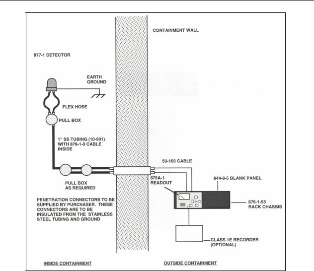
Containment Monitor 875 functions as an accident monitor for reactor containments, refer to Figure 1-1. It consists of the 877-1 Ion Chamber Detector that is located within the reactor containment, and the 876A-1 Readout Module that is contained in a rack in the control room. The readout module contains a power supply that provides the necessary power both for itself and the detector. The readout module is connected to the detector by two cables, a coaxial high voltage cable and a coaxial signal cable. Specifications for the detector and readout module are contained below.
1.2 Specifications
Detector 877-1
Radiation Detected |
Photons above 60 keV |
Range |
1 R/h to 1E7 R/h |
Energy Response |
± 20% from 80 keV to 2 MeV |
Chamber Construction |
Stacked parallel plate, 316 stainless steel housing, 3 |
|
terminal, guarded ion chamber |
Saturation |
>80% up to full scale on instrument |
Collection Voltage |
450 to 550 VDC |
Current Output |
7E-11 to 7E-4 Amp/R/Hr (nominal) |
Chamber Capacitance |
435 picofarads (nominal) |
Voltage Withstand and Leakage |
5E10-5 amperes @ 500 VDC between either ground and |
|
connector pins |
Capacitance |
Approximately 430 pf |
1-1

Victoreen 875
Operators Manual
Hermetic Integrity |
1E10-5 cm3 of helium per second @ one standard |
|
|
atmosphere |
|
Chamber Fill Gas |
Nitrogen/helium (2%) at atmospheric pressure |
|
Dimensions (W x H x D) with Mounting Bracket |
9.25 x 12.5 x 10.06 in |
|
|
(234.95 x 317.5 x 255.52 mm) |
|
Weight |
Approximately 18 lb (8.17 kg) |
|
Temperature, Storage |
40° to 160°F (4° to 71°C) |
|
Temperature, Operating |
40° to 160°F (4° to 71°C) |
|
|
375°F (180°C) peak, accident, 3 hours |
|
Relative Humidity |
100% (waterproof) |
|
Total Integrated Dose |
2E8 Rads + 10% margin, 60Co |
|
Chemical Spray |
0.45 Gallons/minute/ft2 (0.28 molar H3BO3, 3000 ppm |
|
|
Boron, and NaOH; ph of 11, 24 hrs |
|
LOCA Test Duration |
28 days |
|
(Consult Fluke Biomedical, Radiation Management Services, for a complete description of Qualification Test Results)
Readout Module 876A-1
Range
Input Current
Recorder Output optional)
Computer Output optional)
System Accuracy (during "all" conditions)
Power Requirements:
maximum
Temperature Coefficient
Dimensions (W x H x D)
Weight
Environmental Parameters
1 to 107 R/h
Minimum: 6.5 to 7.5 x 10⁻¹¹ A
Maximum: 6.5 to 7.5 x 10⁻⁴ A
0 to +1 VDC, logarithmic (0 - 10 mV and 0 – 5 V
0 to +5 VDC, logarithmic (0 - 100 mV and 0 - 50 mV
(Other Outputs Available Upon Request)
Accumulative @ Meter +36% of input radiation Analog Outputs +28% of input radiation
a)AC Voltage: 108 to 132 VAC, RMS @ 60 ± 3 Hz
b)Battery Power: 22 to 32 VDC @ 600 mA DC
0.40%/°C, + 0.25 R/h/°C
8.46 x 5.25 x 15.21 in
(214.88 x 133.35 x 386.33 mm)
20 lbs (9.07 kg)
Temperature (Storage): 40° to 140°F (4° to 60°C) Temperature (Operating): 40° to 120°F (4° to 49°C)
1-2
|
|
Introduction |
1 |
|
|
Specifications |
|
|
Relative Humidity (Storage): 0 to 95% (non- |
|
|
|
condensation) |
|
|
|
Relative Humidity (Operating): 0 to 90% (non- |
|
|
|
condensation) |
|
|
|
Irradiation: 3.5 to 1 x 10³ Rads @ 60°C integrated over |
||
|
40 years life. |
|
|
Mounting |
876-1-55, Rack Chassis |
|
|
Available Options (consult factory) |
876A-100: Readout, for use with digital systems |
|
|
|
Outputs: 0 |
- 100 mV |
|
|
0 |
- 50 mV |
|
|
0 |
- 10 mV |
|
0 - 5 V
Figure 1-2 illustrates the typical energy response for the detector, Figure 1-3 illustrates typical linearity for the detector and Figure 1-4 illustrates radiation input versus meter reading.
1.3 Equipment Overview
High-Range Containment Monitor Detector (877-1)
The high-range containment monitor detector is an ion chamber detector that has the appearance of a six-inch diameter domed cylinder about seven inches long. Inside the cylinder are two flange-mounted electrodes consisting of 31 flat, disk-shaped plates, each about four inches in diameter, stacked, and mounted on disk rods. The assembly has the appearance of a large air capacitor. The mounting posts are attached to the mounting flange through insulating spacers, so the flange and housing will be neutral with respect to the charges applied to the electrodes.
The whole assembly is covered by the six-inch diameter housing which contacts only the neutral mounting flange. The mounting flange is pierced by three holes. One hole supports the exhaust tube used for exhausting and back filling the chamber. The other two support two 2-pin connectors, one for each electrode. One pin in each pair is connected to the neutral mounting flange. When the coaxial signal cable is connected to this connector, the cable shield is connected to the neutral pin.
The entire chamber is filled with a mixture of helium and nitrogen at atmospheric pressure and sealed.
For further information refer to Section 4, Functional Description.
Readout Module (876A-1)
The 876A-1 Readout Module is designed to give an indication, on an analog meter, of radiation levels within the containment area. The readout is composed of an analog meter, indicator lights and operating switches. The meter has a range of 1 to 107 R/h and is controlled by an eight position rotary switch. The readout is mounted in the 876-1-55 Rack Chassis located in the control room.
For further information refer to Section 4, Functional Description.
Rack Chassis (876-1-55)
The 876-1-55 Rack Chassis permits mounting of two readout modules or one readout module and one optical isolator in a 19-inch wide RETMA equipment rack. The panel height is 5.21 inches.
For further information refer to applicable drawing located in Appendix C.
1-3

Victoreen 875
Operators Manual
Pull Box Assembly (878-12-5)
The 878-12-5 Pull Box Assembly is designed to allow for thermal expansion of the detector cables and to provide a service loop. Various optional pull-box configurations are available per Table 1-1. For more information refer to Section 2, Appendix B, and Appendix C.
Table 1-1. |
Pull-box Variations |
|
|
|
|
|
|
|
|
Model |
Inlet, Size and Location |
Outlet, Size and |
Inlet/Outlet Orientation |
|
Location |
||||
|
|
|
||
878-12 |
1" 270° |
2, ¾", 90° |
180° |
|
|
|
|
|
|
878-12-M 1 |
1" MNPT 270° |
2, ¾", 90° |
180° |
|
|
|
|
|
|
878-12-M2 |
1" MNPT 270° |
2, 1", 90° |
180° |
|
|
|
|
|
|
878-12-M3 |
1" 270° |
1, 1", 90° |
180° |
|
|
|
|
|
|
878-12-M4 |
1" 270° |
1, 1", 90° |
90° |
|
|
|
|
|
|
878-12-M5 |
¾" 270° |
2, ¾", 90 |
180° |
|
|
|
|
|
|
878-12-M6 |
2, ¾" 0°/360° |
2, ¾", 90 |
90° |
|
|
|
|
|
|
878-12-M7 |
1" MNPT 270° |
2, ¾", 90 |
90° |
|
|
|
|
|
|
878-12-M8 |
2, ¾", 0° |
1,1", MNPT, 90° |
90° |
|
|
|
|
|
|
878-12-M9 |
1,1" MNPT 90° |
1, ¾" MNPT, 120° |
150° |
|
|
|
1, ½" MNPT, 210° |
210° |
|
|
|
|
|
|
878-12-M10 |
1,1" MNPT |
2, ¾ 90° |
0° |
|
|
|
|
|
|
878-12-M11 |
2, ¾", 90° |
1,1" MNPT 90° |
0° |
|
|
|
|
|
|
878-12-M12 |
2, ¾", 270° |
1" MNPT, 0° |
90° |
|
|
|
|
|
Flexible Tubing (878-12-30TAB)
1.0 inch diameter flexible stainless steel tubing is available in various lengths to interconnect the 877-1 Detector to the first pull-box.
Cables/Connectors/Panel
In-Containment Cable: (878-1-9-TAB)
Ex-Containment Cable: (50-103-TAB)
Replacement Detector Connector Kit: (878-7-5)
Blank Panel: (844-8-5)
Optional Equipment
The following optional equipment is available:
878-10 Field Calibrator - 250 mCi 137Cs
1-4
Introduction
Equipment Overview 1
Figure 1-1.High-Range Containment Monitor 875
1-5

Victoreen 875
Operators Manual
Figure 1-2.Typical Energy Response Curve – Detector 877-1
1-6
Introduction
Equipment Overview 1
Figure 1-3.Typical Linearity Detector 877-1
Figure 1-4.Radiation Input vs. Meter Reading (Calculated Curve)
1-7

Victoreen 875
Operators Manual
Figure 1-5.High-Range Detector, Recommended Installation
1.4 Receiving Inspection
Upon receipt of the unit:
1.Inspect the carton(s) and contents for damage. If damage is evident, file a claim with the carrier and notify Fluke Biomedical, Radiation Management Services at 440.248.9300.
2.Remove the contents from the packing material.
3.Verify that all items listed on the packing list have been received and are in good condition.


 NOTE
NOTE


If any of the listed items are missing or damaged, notify Fluke Biomedical.
1-8

Introduction
Storage 1
1.5 Storage
Storage of Victoreen instruments must comply with level B storage requirements as outlined in ANSI N45.2.2 (1972) Section 6.1.2(.2). The storage area shall comply with ANSI N45.2.2 (1972) Section 6.2 Storage Area, paragraphs 6.2.1 through 6.2.5. Housekeeping shall conform to ANSI N45.2.3 (1972).
Level B components shall be stored within a fire resistant, tear resistant, weather tight enclosure in a wellventilated building.
Storage of Victoreen instruments must comply with the following:
1.Inspection and examination of items in storage must be in accordance with ANSI N45.2.2 (1972) Section 6.4.1.
2.Requirements for proper storage must be documented and written procedures or instructions must be established.
3.In the event of fire, post-fire evaluation must be in accordance with ANSI N45.2.2 (1972), Section 6.4.3.
4.Removal of items from storage must be in accordance with ANSI N45.2.2 (1972), Sections 6.5 and 6.6.
1.6 Procedures, Warnings, and Cautions
The equipment described in this manual is intended to be used for the detection and measurement of ionizing radiation. It should be used only by persons who have been trained in the proper interpretation of its readings and the appropriate safety procedures to be followed in the presence of radiation.
Although the equipment described in this manual is designed and manufactured in compliance with all applicable safety standards, certain hazards are inherent in the use of electronic and radiometric equipment.
WARNINGS and CAUTIONS are presented throughout this document to alert the user to potentially hazardous situations. A WARNING is a precautionary message preceding an operation that has the potential to cause personal injury or death. A CAUTION is a precautionary message preceding an operation that has the potential to cause permanent damage to the equipment and/or loss of data. Failure to comply with WARNINGS and CAUTIONS is at the user's own risk and is sufficient cause to terminate the warranty agreement between Fluke Biomedical and the customer.
Adequate warnings are included in this manual and on the product itself to cover hazards that may be encountered in normal use and servicing of this equipment. No other procedures are warranted by Fluke Biomedical. It shall be the owner’s or user's responsibility to see to it that the procedures described here are meticulously followed, and especially that WARNINGS and CAUTIONS are heeded. Failure on the part of the owner or user in any way to follow the prescribed procedures shall absolve Fluke Biomedical and its agents from any resulting liability.
Indicated battery and other operational tests must be performed prior to each use to assure that the instrument is functioning properly. If applicable, failure to conduct periodic performance tests in accordance with ANSI N323-1978 (R1983) Radiation Protection Instrumentation Test and Calibration, paragraphs 4.6 and 5.4, and to keep records thereof in accordance with paragraph 4.5 of the same standard, could result in erroneous readings or potential danger. ANSI N323-1978 becomes, by this reference, a part of this operating procedure.
1-9

Victoreen 875
Operators Manual
(Blank page)

Installation
Installation 2
Section 2
Installation
2.1 Installation
Installation of the monitoring system consists of selecting suitable mounting sites for each component of the system, mounting each of the components, and connecting the components into the system configuration.
Installation of this system is as follows:


 NOTE
NOTE


Refer to the applicable drawings in Appendix C for further installation Instructions.
Rack Chassis
The 876-1-55 Rack Chassis is a standard 19-inch chassis with a flame barrier. When seismic qualification is required for the readout, seismic support brackets (P/N 876-1-114) are needed to support the rear of the rack chassis. The brackets are designed to mount on the 19-inch qualified equipment rack. Recommended mounting is shown on drawings GEL876-1-55, and 876-1-114.
Readout Module
Readout Module 876A-1 is designed to fit into one-half of an 876-1-55 Rack Chassis. Insert the readout module in the rack chassis (see drawing GEL876A-1), then insert and tighten the two holding screws in the rear flanges of the rack chassis. The pawl fastener on the front panel of the readout must be tightened.
Optical Isolator (No longer manufactured, consult factory)
Detector


 NOTE
NOTE


The detector case MUST BE PHYSICALLY GROUNDED TO EARTH GROUND. The readout instrument circuit common SHOULD NOT be grounded to earth ground.
The 877-1 Detector is designed to mount on the containment wall. A mounting bracket attached to the detector has four holes that are used for mounting. Studs must be placed in the containment wall before mounting the detector. Dimensions for the studs are the same as the dimensions of the holes in the mounting bracket (refer to drawing GEL877-1). Recommended studs are 5/16 inch Grade 5. No lock washers are to be used and recommended torque for the nuts is 18 ft. lbs. Orient the detector so that the cable connectors are on the underside. Attach the detector to the mounting bracket with the four clamps provided, securing the bolts with a torque of 132 in. lbs. (Figure 1-5 and GEL877-1).
Pull Box
A cable pull box is required to allow for thermal expansion of the detector cables and to provide a service loop. The pull box (drawing 878-12-5) is a typical type that mounts to the containment wall. It should be mounted directly below the detector as shown in Figure 1-1. Depending on actual detector location, more than one pull box may be necessary.
2-1
 Loading...