


 Loading...
INCUTM
Incubator Analyzer
Operators Manual
PN 2206965
April 2005
© 2005 Fluke Corporation All rights reserved. Printed in USA All product names are trademarks of their respective companies.

INCU
Operators Manual
Notices
Fluke Biomedical
6920 Seaway Blvd.
Everett, WA 98203
USA
Customer Service and Sales
USA and Canada:800.648.7952
Outside the USA: 775.883.3400 |
|
Sales Fax: |
775.883.9541 |
Sales E-Mail: |
sales@flukebiomedical.com |
Service: |
888.993.5853 |
Service Fax: |
775.886.6320 |
Service E-mail: |
techservices@flukebiomedical.com |
Internet: |
www.flukebiomedical.com |
For additional sales or service information, contact your local Fluke Biomedical Distributor or Fluke Electronics office.
Restrictions and Liabilities
Information in this document is subject to change and does not represent a commitment by Fluke Biomedical. Changes made to the information in this document will be incorporated in new editions of the publication. No responsibility is assumed by Fluke Biomedical for the use or reliability of software or equipment that is not supplied by Fluke Biomedical or its affiliated dealers.
All Rights Reserved
Copyright 2005, Fluke Biomedical. No part of this publication may be reproduced, transmitted, transcribed, stored in a retrieval system, or translated into any language without the written permission of Fluke Biomedical.
ii

Incubator Analyzer
Notices, Warranty and Contents
Safety Considerations
Warnings and Cautions
Use of this instrument is restricted to qualified personnel who recognize shock hazards and are familiar with safety precautions used when operating electrical equipment. Read the manual carefully before operating the INCU.
The following warning and informational symbols may be found on the INCU.
Symbol |
Description |
Alternating Current
Caution: Refer to accompanying documentation
Master ON/OFF,switch. Push for OFF or ON
Direct / Alternating Current
Direct Current
Enclosure with double insulation or reinforced insolution
Fuse
I P 30 |
Class of protection see Appendix A |
iii

INCU
Operators Manual
Hazard Warnings
Warning! Power Rating. The INCU mains power input must be connected using an external power supply that provides voltage and current within the specified rating for the system.
Warning! Internal Voltage. Always turn off the power switch and unplug the power cord before cleaning the outer surface of the INCU.
Warning! Liquids. Avoid spilling liquids on the analyzer; fluid seepage into internal components creates a potential shock hazard. Do not operate the instrument if internal components are exposed to fluid.
Warning! “Do not use in the presence of oxygen”. The Air Flow sensor is hot wire technology and is a source of combustion if used in the presence of oxygen within the incubator. Use the INCU only in ambient oxygen conditions.
Warning! “Use only approved battery charger." The INCU contains a lead-acid rechargeable battery. Use only the approved charger with proper voltage and current ratings; otherwise, damage to the unit may result.
Precautions
The following precautions are provided to help you avoid damaging the system:
Caution: Service. Authorized service personnel should service the INCU. Only qualified technical personnel should perform troubleshooting and service procedures on internal components.
Caution: Environmental Conditions. Do not expose the system to temperature extremes. Ambient temperatures should remain between 18°C to 40°C. System performance may be adversely affected if temperatures fluctuate above or below this range.
Caution: Do NOT Immerse. Clean only with a mild detergent, and gently wipe down with a clean, lint-free cloth.
Caution: Electromagnetic radiation may affect the noise measurement.
iv

Incubator Analyzer
Notices, Warranty and Contents
Applicable Testing Standards
The INCU has been tested by an independent laboratory and meets the requirements listed here.
Safety Requirements
EC Directive 73/23/EEC
North America
IEC 1010-1, Safety requirement for electrical equipment for measurement, control and laboratory use, Part 1: General Requirements.
Battery Charger is UL marked.
Electromagnetic Interference and Susceptibility
The system meets the requirements of EC Directive 89/336/EEC Electromagnetic Compatibility (see page viii).
USA FCC Class A
Warning: Changes or modifications to this unit not expressly approved by the manufacturer could void the user's authority to operate the equipment.
This equipment has been tested and found to comply with the limits for a Class A digital device, pursuant to Part 15 of the FCC Rules.
These limits are designed to provide reasonable protection against harmful interference when the equipment is operated in a commercial environment. Like all similar equipment, this equipment generates, uses, and can radiate radio frequency energy and, if not installed and used in accordance with the instruction manual, may cause harmful interference to radio communications. Operation of this equipment in a residential area is likely to cause interference, in which case the user will be required to correct the interference at his/her own expense.
Canadian Department of Communications Class A
This digital apparatus does not exceed Class A limits for radio emissions from digital apparatus set out in the Radio Interference Regulations of the Canadian Department of Communications.
Le present appareil numerique n'met pas du bruits radioelectriques depassant les limites applicables aux appareils numerique de la Class A prescrites dans le Reglement sur le brouillage radioelectrique edicte par le ministere des Communications du Canada.
v

INCU
Operators Manual
Based on the testing standards below, this device bears the  mark.
mark.
EC Directive 89/336/EEC Electromagnetic Compatibility
Emissions - Class B
NFEN 55022 Class B (12/94) Radio disturbance
Immunity
The system has been type tested by an independent, accredited testing laboratory and found to meet the requirements for Immunity. Verification of compliance was conducted to the limits and methods of the following:
EN 61000-4-2 (1995) Electrostatic Discharge
EN 61000-4-3 (1984) Radiated EM Fields (electromagnetic radiation may affect the noise measurement)
EN 61000-4-4 (1995) Electrical Fast Transient/Burst EN 61000-4-5 (1995) Surge Immunity
EN 61000-4-6 (1996) Conducted Disturbances
EN 61000-4-11 (1994) Voltage Dips, Short Interruptions and Variations (N/A; Battery buffers transients)
EC Directive 73/23/EEC Low Voltage (User Safety)
The system has been type tested by an independent testing laboratory and found to meet the requirements of EC Directive 73/23/EEC for Low Voltage. Verification of compliance was conducted to the limits and methods of the following:
IEC 1010-1 1990 and Amendments 1 1992 and Amendments 2 1995
“Safety Requirements for Electrical Equipment for Measurement, Control and Laboratory Use, Part 1: General requirements” (including amendments 1 and 2).
vi

Incubator Analyzer
Notices, Warranty and Contents
Warranty
This Warranty is limited and applies only to new products, except for computer-based software, which is covered under a separate Warranty Policy, manufactured by Fluke Biomedical. Fluke Biomedical makes no warranty whatsoever regarding the condition of used products.
Fluke Biomedical warrants the instrument (hereinafter collectively referred to as “Products” or “Product”) for a period of one (1) year from the original purchase date against defective materials or workmanship. This Warranty is limited to the original purchaser (the “Purchaser”) and cannot be assigned or transferred. All claims under this Limited Warranty must be made in writing to Fluke Biomedical, Attention: Service Department. Purchaser must ship the Product to Fluke Biomedical, postage pre-paid. Fluke Biomedical shall either repair or replace with new or like new, at its option and without cost to the Purchaser, any Product which in Fluke Biomedical’s sole judgment is defective by reason of defects in the materials or workmanship.
This Warranty is VOID if the Product has been damaged by accident or misuse, or has been damaged by abuse or negligence in the operation or maintenance of the Product, including without limitation unsafe operation, operation by untrained personnel, and failure to perform routine maintenance. This Warranty is VOID if the Product has been repaired or altered by persons not authorized by Fluke Biomedical, or if the Product has had the serial number altered, effaced, or removed. This Warranty is VOID if any of the Products has not been connected, installed or adjusted strictly in accordance with written directions furnished by Fluke Biomedical. Batteries, fuses, light bulbs, and other “consumable” items used in any of the Products are not covered by this Warranty. Software utilized in conjunction with any of the Products is not covered by the terms of this Warranty but may be covered under a separate Fluke Biomedical software warranty.
We will continue to stock parts for a maximum period of five (5) years after the manufacture of any equipment has been discontinued. Parts shall include all materials, charts, instructions, diagrams, and accessories that were furnished with the standard models.
THIS WARRANTY CONTAINS THE ENTIRE OBLIGATION OF FLUKE BIOMEDICAL, AND NO OTHER WARRANTIES, EXPRESSED, IMPLIED, OR STATUTORY ARE GIVEN. PURCHASER AGREES TO ASSUME ALL LIABILITY FOR ANY DAMAGES AND/OR BODILY INJURY OR DEATH THAT MAY RESULT FROM THE USE OR MISUSE OF ANY EQUIPMENT OR INSTRUMENT BY THE PURCHASER, HIS EMPLOYEES, AGENTS, OR CUSTOMERS, OTHER THAN THE EXPRESS WARRANTY CONTAINED HEREIN. WE SHALL NOT BE RESPONSIBLE FOR ANY DIRECT OR CONSEQUENTIAL DAMAGES OF ANY KIND. THIS WARRANTY SHALL NOT BE CHANGED OR MODIFIED IN ANY WAY WITHOUT THE EXPRESS WRITTEN PERMISSION OF AN OFFICER OF FLUKE BIOMEDICAL.
THIS WARRANTY IS VOID UNLESS THE PURCHASE REGISTRATION CARD HAS BEEN COMPLETED AND MAILED TO US WITHIN TEN (10) DAYS OF PURCHASE.
vii

INCU
Operators Manual
About This Manual
This manual provides a complete description of the INCU Incubator Analyzer and its applications. The manual is organized as follows:
•Chapter 1, Overview: An introduction to the INCU and optional accessories
•Chapter 2, Installation: How to connect the INCU and install the PC software
•Chapter 3, General Operation: INCU keypad functions, setup, and stand-alone operation
•Chapter 4, PC Software Operation: PC software operation
•Chapter 5, Safety, Displayed Messages, Troubleshooting, and Support
•Appendix A, INCU Specifications
•Appendix B, INCU Report Examples
•Appendix C, DAT File Format
viii

Incubator Analyzer
Notices, Warranty and Contents
Contents
Notices ................................................................................................................... |
ii |
Restrictions and Liabilities ........................................................................ |
ii |
All Rights Reserved................................................................................... |
ii |
Safety Considerations............................................................................................ |
iii |
Warnings and Cautions............................................................................ |
iv |
Hazard Warnings............................................................................... |
iv |
Precautions........................................................................................ |
iv |
Applicable Testing Standards ................................................................................ |
v |
Safety Requirements ................................................................................ |
v |
Electromagnetic Interference and Susceptibility....................................... |
v |
EC Directive 89/336/EEC Electromagnetic Compatibility................... |
vi |
Emissions............................................................................................ |
vi |
Immunity ............................................................................................. |
vi |
EC Directive 73/23/EEC Low Voltage (User Safety) ............................... |
vi |
Warranty............................................................................................................. |
vivii |
About This Manual ............................................................................................... |
viii |
Chapter 1: Overview ................................................................................ |
1-1 |
Introducing the INCU™....................................................................................... |
1-2 |
INCU Measurements........................................................................................... |
1-3 |
Getting to Know the INCU................................................................................... |
1-4 |
AAMI/IEC Standards ........................................................................................... |
1-6 |
INCU Applications.................................................................................. |
1-6 |
Accessories......................................................................................................... |
1-8 |
Chapter 2: Installation ............................................................................. |
2-1 |
Unpacking and Inspection................................................................................... |
2-2 |
Connecting INCU ................................................................................................ |
2-3 |
AC-DC Battery Charger Connection...................................................... |
2-3 |
Internal Battery....................................................................................... |
2-3 |
RS-232 Port ........................................................................................... |
2-3 |
Air Flow Sensor...................................................................................... |
2-4 |
Radiant Baby Assembly......................................................................... |
2-4 |
PC Software System Requirements ................................................................... |
2-5 |
Installing the PC Software................................................................................... |
2-6 |
Installing the Software............................................................................ |
2-6 |
ix

INCU
Operators Manual
Chapter 3: General Operation................................................................. |
3-1 |
INCU Keypad Functions ..................................................................................... |
3-2 |
Key Details............................................................................................. |
3-3 |
INCU Setup......................................................................................................... |
3-5 |
Placement of the INCU in the Incubator................................................ |
3-5 |
Infant Radiant Warmers......................................................................... |
3-9 |
INCU Operation ................................................................................... |
3-10 |
Chapter 4: INCU PC Software Operation ............................................... |
4-1 |
Introduction ......................................................................................................... |
4-2 |
Configuring the INCU for Data Acquisition ......................................................... |
4-2 |
Data Acquisition.................................................................................................. |
4-4 |
Transferring Data to the PC Software ................................................................ |
4-5 |
Graphs ................................................................................................................ |
4-7 |
Software Options ................................................................................................ |
4-8 |
Open Files ............................................................................................. |
4-8 |
Save Files.............................................................................................. |
4-8 |
Printer Configuration.............................................................................. |
4-8 |
Print Folder ............................................................................................ |
4-8 |
Cascade................................................................................................. |
4-9 |
Heading ............................................................................................... |
4-10 |
Graph Colors ....................................................................................... |
4-11 |
Com Port.............................................................................................. |
4-12 |
Language............................................................................................. |
4-12 |
Zoom.................................................................................................... |
4-13 |
Chapter 5: Safety, Displayed Messages, Troubleshooting, |
|
and Support........................................................................... |
5-1 |
Electrical Safety.................................................................................................. |
5-2 |
Cleaning................................................................................................. |
5-2 |
Air Flow Sensor ..................................................................................... |
5-2 |
Displayed Messages .......................................................................................... |
5-3 |
Troubleshooting.................................................................................................. |
5-4 |
Support ............................................................................................................... |
5-6 |
Appendix A: Specifications .................................................................... |
A-1 |
Appendix B: Report Examples ............................................................... |
B-1 |
Appendix C: DAT File Format................................................................. |
C-1 |
x
Incubator Analyzer
Notices, Warranty and Contents
List of Illustrations
Figure 1-1. Closed Incubator With Forced Convection....................................... |
1-3 |
Figure 1-2. Infant Warmer................................................................................... |
1-3 |
Figure 1-3. Descriptions and Locations of INCU Sensors .................................. |
1-4 |
Figure 1-4. View of Right Side of INCU .............................................................. |
1-5 |
Figure 1-5. View of Left Side of INCU................................................................. |
1-5 |
Figure 2-1. Radiant Baby Assembly ................................................................... |
2-4 |
Figure 2-2. INCU Setup Screen .......................................................................... |
2-6 |
Figure 3-1. The INCU Front Panel ...................................................................... |
3-2 |
Figure 3-2. INCU Keypad Display....................................................................... |
3-3 |
Figure 3-3. INCU Inside a Closed Incubator....................................................... |
3-5 |
Figure 3-4. Placement of Temperature Sensors T1-T3 ...................................... |
3-6 |
Figure 3-5. Placement of Air Flow Sensor .......................................................... |
3-7 |
Figure 3-6. Placement of Temperature Sensor T4 ............................................. |
3-8 |
Figure 3-7. Placement of an INCU Inside an Infant Warmer .............................. |
3-9 |
Figure 3-8. Placement of a Radiant Baby Adapter on Top of the INCU ............. |
3-9 |
Figure 3-9. Data Acquisition Mode Screen ....................................................... |
3-11 |
Figure 4-1. PC Interconnected With the INCU.................................................... |
4-2 |
Figure 4-2. Using the Config Menu ..................................................................... |
4-3 |
Figure 4-3. INCU Keypad Display....................................................................... |
4-4 |
Figure 4-4. INCU File Transfer Menu.................................................................. |
4-5 |
Figure 4-5. INCU Comments Entry Window ....................................................... |
4-6 |
Figure 4-6. INCU Parameter Options Menu........................................................ |
4-7 |
Figure 4-7. INCU Parameter Screen................................................................... |
4-7 |
Figure 4-8. INCU File Menu Screen.................................................................... |
4-8 |
Figure 4-9. INCU Window Menu Screen............................................................. |
4-9 |
Figure 4-10. INCU Parameters Menu Screen..................................................... |
4-9 |
Figure 4-11. INCU Heading Screen .................................................................. |
4-10 |
Figure 4-12. INCU Graph Colors Screen .......................................................... |
4-11 |
Figure 4-13. INCU Communication Menu Screen ............................................ |
4-12 |
Figure 4-14. INCU Language Menu Screen ..................................................... |
4-12 |
Figure 4-15. INCU Zoom Menu Screen ............................................................ |
4-13 |
Figure 4-16. INCU Zoom on Window Screen ................................................... |
4-13 |
Figure B-1. Sample Monitoring Sheet................................................................ |
B-3 |
Figure B-2. Sample History Graph Sheet .......................................................... |
B-4 |
Figure B-3. Sample Parameter Numerical List .................................................. |
B-5 |
xi

INCU
Operators Manual
xii

Chapter 1: Overview |
|
1 |
|
|
|
||
|
|
|
|
|
|
|
|
|
|
|
|
Inside This Chapter
•Introducing INCUTM
•INCUTM Measurements
•Getting to Know INCUTM
•AAMI/IEC Standards
•Accessories
1-1

INCU
Operators Manual
Introducing INCUTM
The INCU Incubator Analyzer is a portable device designed to verify the proper operation and environment of infant incubators. This unit records parameters important to the care of infants over time, such as airflow, sound level, temperature (four individual measurement probes), and relative humidity. Event markers can be placed on the recording to identify certain activities or periods. The rechargeable battery allows the unit to be placed within the incubator chamber for up to 24 hours without compromising the integrity of the environment.
The INCU can operate stand-alone or with the use of a personal computer. With a PC, the user selects the desired record time/interval via the software, and then initiates the start of the test from the INCU. After completion of the test, the user uploads the data collected by INCU into the PC software for display and analysis. The user may store the recorded data in a file or print the data to a report. In stand-alone mode, the unit displays all measured parameters repeatedly in cycle fashion, and no data is recorded.
Features on the INCU include:
•Portability: Sits in place of the infant within the incubator.
•Multiple Sensors: Measures and documents multiple key infant incubator parameters simultaneously.
•Compliance: Measures most parameters according to IEC and AAMI standards.
•Efficient: Saves time in testing critical infant incubators.
•Data Collection: Uses Microsoft® Windows® software for evaluation and documentation.
•Reporting: Allows printing of numerical and graphical reports.
•Recording Flexibility: Provides adjustable measurement intervals.
•Two Modes of Operation: Operates stand-alone or fully functioning, requiring a computer.
1-2

Incubator Analyzer
Getting to Know the INCU
INCU is to be used by service personnel or Biomedical institutions to verify and test infant incubators. INCU is designed to support testing of two types of incubators, as shown in Figures 1-1 and 1-2.
Figure 1-1. Closed incubator with forced convection |
Figure 1-2. Infant warmer |
INCU Measurements
INCU is an autonomous acquisition system that is used to measure and save the operational parameters of an empty incubator, and then transmit data via a serial communications port. INCU provides, in a single unit, the measurement systems that allow you to record the multiple parameters simultaneously.
The following measurement parameters are recorded:
Temperature – 4 Sensors T1-T4
Relative Humidity – 1 Sensor Air Flow – 1 Sensor
Sound – 1 Sensor
See Appendix A, Specifications for performance specifications.
1-3

INCU
Operators Manual
Getting to Know the INCU
Sensors are integrated and stored within INCU. Open INCU by releasing the latch on the top cover. Fold the covers open to expose the sensors when taking measurements. Figure 1-3 shows the location of each sensor.
Figure 1-3. INCU sensors
•Temperature Sensor T1: Used for Convection measurements.
•Temperature Sensor T2: Used for Convection or Radiant measurements; used with radiant baby adapter supplied with INCU.
•Temperature Sensor T3: Used for Convection measurements.
•Relative Humidity: Located in right top cover (cover must be open for proper measurements).
•Air Flow: Detachable for storage.
•ON/OFF Switch: Top cover engages this switch to turn power off to INCU automatically, if the master On/Off switch is left in the ON position and the top covers are closed (master switch is on the left side of the exterior).
•Temperature Probe Holder: Used to hold temperature probe T2 when taking convection measurements. This is a mechanical connection only; there is no electrical connection.
1-4
Incubator Analyzer
AAMI/IEC Standards
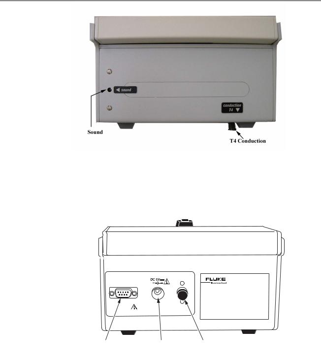
Figure 1-4. View of right side of INCU
•Sound Sensor: Internal Microphone used for sound measurements.
•Temperature Sensor T4: Used for Mattress Temperature Measurements, made by conduction.
RS 232
DO NOT USE WITH OXYGEN
NE PAS UTILISER EN PRESENCE
D'OXYGENE
 INCU INCUBATOR ANALYZER
RS 232 |
Power |
On/Off Switch |
Port |
DC in Jack |
|
Figure 1-5. View of left side of INCU
•RS-232 Port: 9 Pin D Sub type Male Connector.
•Power DC IN Jack: Use only the specified charger. AC-DC 6V 600 mA.
•Master On/Off Switch: Push for OFF or ON.
1-5

INCU
Operators Manual
AAMI/IEC Standards
The AAMI and IEC standards specify sound levels, CO2 concentration, and thermal characteristics for incubators. The standards are used by manufacturers when designing and manufacturing incubators. INCU was designed with consideration of the standards, and can perform testing to satisfy many testing requirements.
|
Incubator Standards |
|
Standard# |
|
Description |
IEC 601-2-19 |
|
Infant Incubator Tester Safety Requirements |
IEC 601-2-20 |
|
Safety Requirements for Transport Incubators |
IEC 601-2-21 |
|
Infant Radiant Warmer Standard |
ANSI/AAMI 1136-1997 |
|
Infant Incubators |
Note: For up-to-date standards, please visit AAMI.org or IEC.org.
Note: The following are examples of standards for description proposed. Please reference the current application to determine your testing protocol.
INCU Applications
The following section provides information describing how INCU can be used to perform testing in consideration of the standards.
1.Temperature – Standard: During steady state condition, the INCUBATOR TEMPERATURE shall not differ from the AVERAGE INCUBATOR TEMPERATURE by more than 0.5°C (1°C transportable) during at least 1 hour at the control temperatures of 32°C and 36°C.
INCU: The user shall check the oscillation from min to max in steady state.
2.Temperature - Standard: The AVERAGE TEMPERATURE in each point A,B,C,D,E, shall not differ from the AVERAGE INCUBATOR TEMPERATURE (test at a set T of 32°C - 36°C) by more than ±0.8°C (±1.5°C transportable).
INCU: In any position of the tilted mattress, it shall not differ by more than ±1.0°C (±2.0°C transportable). Calculate manually the difference between the mean value at the center and the other sensors readings.
3.Temperature - Standard: The TEMPERATURE as measured by the skin temperature sensor shall not differ from a reference sensor temperature by more than 0.3°C in steady temperature condition.
INCU: Check the difference between the value given by the T2 sensor and the value displayed by the skin sensor when placed in close proximity to the T2 sensor.
1-6

Incubator Analyzer
AAMI/IEC Standards
4.Temperature - Standard: The INCUBATOR shall be provided with an indicator of the internal temperature. The mean value of the reading of this device shall not differ from the average incubator temperature measured by a standard thermometer by more than ±0.8°C (±1°C transportable), less the standard thermometer error. The standard thermometer shall be accurate within ±0.05°C.
INCU: Check the difference between the value of the mean value at the center and the one displayed by the indicator.
5.Temperature - Standard: Working as an air-controlled INCUBATOR, the average INCUBATOR TEMPERATURE shall not differ from the control temperature by more than ±1.5°C (±2°C transportable).
INCU: Check the difference between the value of the mean value at the center and the set value.
6.Temperature - Standard: The warm-up time of the equipment shall not differ by more than 20% from the warm-up time specified in the instructions for use.
INCU: Check the difference between the time stated by the manufacturer and the time to raise the temperature by 11 C, starting at the environmental conditions with a setting temperature 12°C above the ambient.
7.Temperature - Standard: After adjusting the temperature from 30°C to 34°C or Transit 32°C to 36°C, the overshoot in the incubator temperature shall not exceed 2°C.
INCU: Calculate the overshoot manually.
8.Standard: Any indicated value of relative humidity shall have an accuracy of ±10% (±15% transportable) of the actual measured value.
INCU: Read the value and compare it with the set value.
9.Sound Pressure - Standard: In normal use, the sound level within the baby compartment shall not exceed 60 dB except as specified in 102.2.
INCU: Read the value and compare it with the threshold.
10.Sound Pressure - Standard: When any incubator alarm is sounding, the sound level within the baby compartment shall not exceed 80 dB.
INCU: Activate an alarm, read the value, and compare it with the threshold.
11.Sound Pressure - Standard: Audible alarms shall have a sound level of at least 80 dB at a distance of 3 m perpendicular to the front of the control unit.
INCU: Activate an alarm, move the INCU outside, read the value, and compare it with the threshold.
1-7

INCU
Operators Manual
12.Air Flow – Standard: In normal use, air velocity over the mattress shall not exceed 0.35 m/s.
INCU: Read the value and compare it with the threshold.
Accessories
The following accessories are available for your INCU Incubator Analyzer.
Description |
Part No. |
DB9 Serial Cable |
2238834 |
Transport Bag |
2248900 |
Radiant Baby Assembly |
2239002 |
Outside Temperature Probe Holder |
2213928 |
Service Manual |
2206983 |
1-8
Chapter 2: Installation |
|
2 |
|
|
|
||
|
|
|
|
|
|
|
|
|
|
|
|
Inside This Chapter
•Unpacking and Inspection
•Connecting INCUTM
•PC Software System Requirements
•Installing the PC Software
2-1

INCU
Operators Manual
Unpacking and Inspection
Before unpacking the INCU, visually inspect the shipping box for damage.
If no damage is evident, unpack the INCU and use the checklist below to ensure that you have received the instrument accessories. Save the foam inserts and shipping box. You must use the original packing materials when shipping the INCU for service or re-calibration. If the original shipping carton and packing materials are not available, call a Fluke service representative for assistance.
If the shipping box is damaged, unpack the analyzer and inspect it for visible defects.
If the instrument is damaged, notify the carrier and your local dealer or service center. Keep the shipping cartons and packing materials for the carrier's inspection. Call a Fluke service representative to arrange for repair or replacement of your instrument without waiting for the claim against the carrier to be settled.
After unpacking the INCU, use the following checklist to ensure that you have received everything. In addition to the analyzer and this manual (P/N 3901000), you should have the following:
•A Transport Bag, P/N 2248900
•An Air Flow Sensor, P/N 2239025
•PC Software CD ROM, P/N 2213919
•AC Battery Charger with Country Adapters for the USA, Europe, Australia, or the UK, P/N 2213937
•9-Pin to 9-Pin Serial Cable, P/N 2238834
•Temperature Probe Holder, P/N 2213928
•Radiant Baby Assembly, P/N 2239002
•Certificate of Calibration
•Declaration of Conformity
•Fluke Biomedical Warranty Card Information
2-2
Loading...