


 Loading...
CuffLink
NIBP Analyzer
Operators Manual
PN 2242915
December 2007, Rev. 1, 9/09
© 2007, 2009 Fluke Corporation, All rights reserved. Printed in USA. Specifications subject to change without notice. All product names are trademarks of their respective companies.
Warranty and Product Support
Fluke Biomedical warrants this instrument against defects in materials and workmanship for one year from the date of original purchase. During the warranty period, we will repair or at our option replace, at no charge, a product that proves to be defective, provided you return the product, shipping prepaid, to Fluke Biomedical. This warranty covers the original purchaser only and is not transferable. The warranty does not apply if the product has been damaged by accident or misuse or has been serviced or modified by anyone other than an authorized Fluke Biomedical service facility. NO OTHER WARRANTIES, SUCH AS FITNESS FOR A PARTICULAR PURPOSE, ARE EXPRESSED OR IMPLIED. FLUKE SHALL NOT BE LIABLE FOR ANY SPECIAL, INDIRECT, INCIDENTAL OR CONSEQUENTIAL DAMAGES OR LOSSES, INCLUDING LOSS OF DATA, ARISING FROM ANY CAUSE OR THEORY.
This warranty covers only serialized products and their accessory items that bear a distinct serial number tag. Recalibration of instruments is not covered under the warranty
This warranty gives you specific legal rights and you may also have other rights that vary in different jurisdictions. Since some jurisdictions do not allow the exclusion or limitation of an implied warranty or of incidental or consequential damages, this limitation of liability may not apply to you. If any provision of this warranty is held invalid or unenforceable by a court or other decision-maker of competent jurisdiction, such holding will not affect the validity or enforceability of any other provision.
07/07

Notices
All Rights Reserved
♥ Copyright 2007, Fluke Biomedical. No part of this publication may be reproduced, transmitted, transcribed, stored in a retrieval system, or translated into any language without the written permission of Fluke Biomedical.
Copyright Release
Fluke Biomedical agrees to a limited copyright release that allows you to reproduce manuals and other printed materials for use in service training programs and other technical publications. If you would like other reproductions or distributions, submit a written request to Fluke Biomedical.
Unpacking and Inspection
Follow standard receiving practices upon receipt of the instrument. Check the shipping carton for damage. If damage is found, stop unpacking the instrument. Notify the carrier and ask for an agent to be present while the instrument is unpacked. There are no special unpacking instructions, but be careful not to damage the instrument when unpacking it. Inspect the instrument for physical damage such as bent or broken parts, dents, or scratches.
Technical Support
For application support or answers to technical questions, either email techservices@flukebiomedical.com or call 1-800- 648-7952 or 1-425-446-6945.
Claims
Our routine method of shipment is via common carrier, FOB origin. Upon delivery, if physical damage is found, retain all packing materials in their original condition and contact the carrier immediately to file a claim. If the instrument is delivered in good physical condition but does not operate within specifications, or if there are any other problems not caused by shipping damage, please contact Fluke Biomedical or your local sales representative.
Standard Terms and Conditions
Refunds and Credits
Please note that only serialized products and their accessory items (i.e., products and items bearing a distinct serial number tag) are eligible for partial refund and/or credit. Nonserialized parts and accessory items (e.g., cables, carrying cases, auxiliary modules, etc.) are not eligible for return or refund. Only products returned within 90 days from the date of original purchase are eligible for refund/credit. In order to receive a partial refund/credit of a product purchase price on a serialized product, the product must not have been damaged by the customer or by the carrier chosen by the customer to return the goods, and the product must be returned complete (meaning with all manuals, cables, accessories, etc.) and in “as new” and resalable condition. Products not returned within 90 days of purchase, or products which are not in “as new” and resalable condition, are not eligible for credit return and will be returned to the customer. The Return Procedure (see below) must be followed to assure prompt refund/credit.
Restocking Charges
Products returned within 30 days of original purchase are subject to a minimum restocking fee of 15 %. Products returned in excess of 30 days after purchase, but prior to 90 days, are subject to a minimum restocking fee of 20 %. Additional charges for damage and/or missing parts and accessories will be applied to all returns.
Return Procedure
All items being returned (including all warranty-claim shipments) must be sent freight-prepaid to our factory location. When you return an instrument to Fluke Biomedical, we recommend using United Parcel Service, Federal Express, or Air Parcel Post. We also recommend that you insure your shipment for its actual replacement cost. Fluke Biomedical will not be responsible for lost shipments or instruments that are received in damaged condition due to improper packaging or handling.
Use the original carton and packaging material for shipment. If they are not available, we recommend the following guide for repackaging:
Use a double-walled carton of sufficient strength for the weight being shipped.
Use heavy paper or cardboard to protect all instrument surfaces. Use nonabrasive material around all projecting parts.
Use at least four inches of tightly packed, industry-approved, shock-absorbent material around the instrument.
Returns for partial refund/credit:
Every product returned for refund/credit must be accompanied by a Return Material Authorization (RMA) number, obtained from our Order Entry Group at 1-800-648-7952 or 1-425-446-6945.

Repair and calibration:
To find the nearest service center, go to www.flukebiomedical.com/service, or
In the U.S.A.:
Cleveland Calibration Lab
Tel: 1-800-850-4606
Email: globalcal@flukebiomedical.com
Everett Calibration Lab
Tel: 1-888-993-5853
Email: service.status@fluke.com
In Europe, Middle East, and Africa:
Eindhoven Calibration Lab
Tel: +31-402-675300
Email: ServiceDesk@fluke.com
In Asia:
Everett Calibration Lab
Tel: +425-446-6945
Email: service.international@fluke.com
Certification
This instrument was thoroughly tested and inspected. It was found to meet Fluke Biomedical’s manufacturing specifications when it was shipped from the factory. Calibration measurements are traceable to the National Institute of Standards and Technology (NIST). Devices for which there are no NIST calibration standards are measured against in-house performance standards using accepted test procedures.
WARNING
Unauthorized user modifications or application beyond the published specifications may result in electrical shock hazards or improper operation. Fluke Biomedical will not be responsible for any injuries sustained due to unauthorized equipment modifications.
Restrictions and Liabilities
Information in this document is subject to change and does not represent a commitment by Fluke Biomedical. Changes made to the information in this document will be incorporated in new editions of the publication. No responsibility is assumed by Fluke Biomedical for the use or reliability of software or equipment that is not supplied by Fluke Biomedical, or by its affiliated dealers.
Manufacturing Location
The CuffLink NIBP Analyzer is manufactured in Everett, Washington by Fluke Biomedical, 6920 Seaway Blvd., Everett, WA, U.S.A.
Table of Contents
Chapter |
Title |
Page |
1 |
Introduction and Specifications......................................................... |
1-1 |
|
Introduction........................................................................................................ |
1-3 |
|
Standard Features............................................................................................... |
1-4 |
|
New Features (Firmware Revision 3.0 and Later)............................................. |
1-4 |
|
Arrhythmias................................................................................................... |
1-4 |
|
Pressure Testing............................................................................................. |
1-5 |
|
Remote Commands ....................................................................................... |
1-6 |
|
General Safety Considerations........................................................................... |
1-6 |
|
Symbols ......................................................................................................... |
1-6 |
|
Warnings and Cautions.................................................................................. |
1-7 |
|
Instrument Familiarity ....................................................................................... |
1-8 |
|
Specifications..................................................................................................... |
1-12 |
|
Accessories ........................................................................................................ |
1-16 |
2 |
Operation ............................................................................................. |
2-1 |
|
Powering Up the Analyzer................................................................................. |
2-3 |
|
Menu Structure and Navigation ......................................................................... |
2-3 |
|
Preliminary Procedures...................................................................................... |
2-6 |
|
Assembling Equipment ................................................................................. |
2-6 |
|
Making Connections...................................................................................... |
2-8 |
|
Observing Results.......................................................................................... |
2-9 |
|
Selecting Heart Rate (HtRate) ....................................................................... |
2-10 |
|
Adjusting the Pressure Envelope (AdjEnv)................................................... |
2-11 |
|
Simulating Adult Blood Pressure....................................................................... |
2-14 |
|
Setting Zero Pressure..................................................................................... |
2-15 |
|
Simulating Other ADAMS Family Target Values ........................................ |
2-16 |
|
NIBP Monitor Testing Sequence................................................................... |
2-16 |
|
Simulating Neonatal Blood Pressure ................................................................. |
2-17 |
|
Simulating Arrhythmias..................................................................................... |
2-18 |
|
Pressure Testing................................................................................................. |
2-19 |
|
Leak Testing .................................................................................................. |
2-19 |
|
Manometer Function ..................................................................................... |
2-20 |
|
Pop Off Test .................................................................................................. |
2-21 |
|
Utility Functions ................................................................................................ |
2-22 |
i

Cufflink
Operators Manual
|
Set Clock ....................................................................................................... |
2-22 |
|
Pop Time ....................................................................................................... |
2-24 |
|
Logo............................................................................................................... |
2-25 |
|
System Functions........................................................................................... |
2-25 |
|
Establishing Communications ........................................................................... |
2-31 |
|
Configuring RS232........................................................................................ |
2-31 |
|
Testing the RS232 Port and Connections ...................................................... |
2-32 |
|
Using Auto Sequences ....................................................................................... |
2-33 |
|
Executing an Auto Sequence......................................................................... |
2-33 |
|
Utilities .......................................................................................................... |
2-34 |
|
Printing Documents ........................................................................................... |
2-37 |
|
Printing Blood Pressure Test Results ............................................................ |
2-37 |
|
Printing Manometer, Leak Test, and Overpressure Test Results .................. |
2-38 |
|
Printing Auto Sequences ............................................................................... |
2-38 |
3 |
Remote Operation ............................................................................... |
3-1 |
|
Introduction........................................................................................................ |
3-3 |
|
Setting Up the medTester .................................................................................. |
3-3 |
|
Remote Command Syntax ................................................................................. |
3-4 |
|
Command Syntax for medTester................................................................... |
3-4 |
|
Command Syntax for Computer.................................................................... |
3-4 |
|
Command Parameters.................................................................................... |
3-4 |
|
Terminating Characters ................................................................................. |
3-5 |
|
Error Messages .............................................................................................. |
3-5 |
|
Command Descriptions...................................................................................... |
3-7 |
|
BEEP ............................................................................................................. |
3-7 |
|
CALPUCKPOS ............................................................................................. |
3-8 |
|
DEFLATE ..................................................................................................... |
3-8 |
|
DRAWENV................................................................................................... |
3-8 |
|
DRAWENVNEO .......................................................................................... |
3-11 |
|
DRAWPULSE............................................................................................... |
3-15 |
|
GLOBALINIT............................................................................................... |
3-17 |
|
GOTOLOCAL............................................................................................... |
3-18 |
|
IDENT ........................................................................................................... |
3-18 |
|
INFLATE ...................................................................................................... |
3-18 |
|
KEYTEST ..................................................................................................... |
3-19 |
|
LEAKTEST................................................................................................... |
3-19 |
|
MAKEARM .................................................................................................. |
3-20 |
|
MAKEARMNEO .......................................................................................... |
3-23 |
|
MANOMETER ............................................................................................. |
3-27 |
|
MKARM10.................................................................................................... |
3-27 |
|
MKARM20.................................................................................................... |
3-27 |
|
MKARM30.................................................................................................... |
3-28 |
|
MKARM40.................................................................................................... |
3-28 |
|
MKARM50.................................................................................................... |
3-28 |
|
MKARM60.................................................................................................... |
3-28 |
|
MKARM70.................................................................................................... |
3-29 |
|
MKARMNEO10 ........................................................................................... |
3-29 |
|
MKARMNEO20 ........................................................................................... |
3-29 |
|
MKARMNEO30 ........................................................................................... |
3-29 |
|
MKARMNEO40 ........................................................................................... |
3-30 |
|
MKARMNEO50 ........................................................................................... |
3-30 |
|
MKARR_AF ................................................................................................. |
3-30 |
|
MKARR_MB ................................................................................................ |
3-30 |
ii
|
|
Contents (continued) |
|
|
|
|
MKARR_PAC............................................................................................... |
3-31 |
|
MKARR_PVC............................................................................................... |
3-31 |
|
MKARR_AS ................................................................................................. |
3-31 |
|
POPOFF ........................................................................................................ |
3-32 |
|
PRINTTEST.................................................................................................. |
3-32 |
|
PSCALE ........................................................................................................ |
3-33 |
|
PULSE........................................................................................................... |
3-34 |
|
PUMPPCB..................................................................................................... |
3-36 |
|
RCUSERENV ............................................................................................... |
3-36 |
|
RDCLOCK.................................................................................................... |
3-36 |
|
RDENVGAIN ............................................................................................... |
3-36 |
|
RDENVSHIFT .............................................................................................. |
3-37 |
|
RDPEAKDIV................................................................................................ |
3-37 |
|
RDQCDATE ................................................................................................. |
3-37 |
|
RDUSERENV ............................................................................................... |
3-37 |
|
READPRESS ................................................................................................ |
3-38 |
|
RESET........................................................................................................... |
3-38 |
|
STUSERENV................................................................................................ |
3-39 |
|
WRCLOCK ................................................................................................... |
3-39 |
|
WRPEAKDIV ............................................................................................... |
3-40 |
|
WRUSERENV .............................................................................................. |
3-40 |
|
ZEROPRESS................................................................................................. |
3-41 |
|
Programming with Analyzer Commands........................................................... |
3-41 |
|
Checklist Generated in BASIC...................................................................... |
3-41 |
|
Adult BP Checklists and Test Results ........................................................... |
3-43 |
|
Neonate BP Checklists and Test Results....................................................... |
3-47 |
|
Adult Arrhythmic BP Checklists and Test Results........................................ |
3-51 |
|
Additional Command Descriptions (Firmware Version 3.20)........................... |
3-55 |
|
PUMPON ...................................................................................................... |
3-55 |
|
PUMPOFF..................................................................................................... |
3-55 |
|
VALVEOPEN ............................................................................................... |
3-55 |
|
VALVECLOSED .......................................................................................... |
3-56 |
4 |
Maintenance, Service, and Calibration.............................................. |
4-1 |
|
Maintenance....................................................................................................... |
4-3 |
|
Avoiding Damage.......................................................................................... |
4-3 |
|
Cleaning......................................................................................................... |
4-3 |
|
Service and Calibration...................................................................................... |
4-3 |
Appendices |
|
|
|
A Non-Invasive Blood Pressure (NIBP) Monitoring Tutorial ........................ |
A-1 |
|
B Glossary....................................................................................................... |
B-1 |
iii

Cufflink
Operators Manual
iv
List of Tables
Table |
Title |
Page |
1-1. |
New RS232 Remote Commands............................................................................ |
1-6 |
1-2. |
Symbols.................................................................................................................. |
1-6 |
1-3. |
Analyzer Top and Front Panel Controls and Indicators ......................................... |
1-8 |
1-4. |
Rear Panel Controls and Indicators........................................................................ |
1-11 |
1-5. |
Standard Accessories ............................................................................................. |
1-16 |
2-1. |
Blood Pressure Parameters Provided by the Select BP Option.............................. |
2-6 |
2-2. |
Measured Test Parameters ..................................................................................... |
2-10 |
2-3. |
Arrhythmia Types .................................................................................................. |
2-18 |
2-4. |
Leak Test Utility Options....................................................................................... |
2-20 |
2-5. Measured Leak Test Parameters ............................................................................ |
2-20 |
|
2-6. |
Measured Manometer Parameters.......................................................................... |
2-21 |
2-7. Measured Pop Off Test Parameters........................................................................ |
2-22 |
|
2-8. |
Speaker Tests and Adjustments.............................................................................. |
2-27 |
2-9. |
Display Test Descriptions ...................................................................................... |
2-28 |
2-10. |
Pop Time and Comm Port Default Values............................................................. |
2-29 |
2-11. |
Auto Sequence Defaults......................................................................................... |
2-30 |
2-12. |
RS232 Settings ....................................................................................................... |
2-32 |
3-1. |
medTester Remote Configuration Settings ............................................................ |
3-3 |
3-2. |
Available Error Messages ...................................................................................... |
3-6 |
3-3. |
Autosequence Defaults........................................................................................... |
3-17 |
3-4. |
Pop Time and Comm Port Default Values............................................................. |
3-17 |
v

Cufflink
Operators Manual
vi
List of Figures
Figure |
Title |
Page |
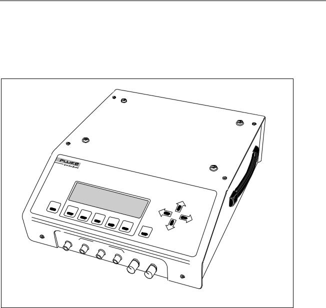
1-1. |
CuffLink Non-Invasive Blood Pressure Analyzer ................................................. |
1-3 |
1-2. |
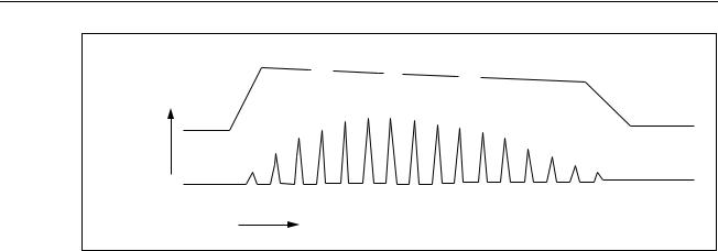
Cuff pressure waveform during blood pressure measurement ............................... |
1-4 |
1-3. |
Analyzer Top and Front Panel Controls and Indicators ......................................... |
1-8 |
1-4. |
Rear Panel Controls and Indicators........................................................................ |
1-11 |
2-1. |
Analyzer Menu Map .............................................................................................. |
2-4 |
2-2. |
Adjustments for Adult Cuff Mandrel ..................................................................... |
2-7 |
2-3. |
Neonate Mandrel.................................................................................................... |
2-7 |
2-4. |
NIBP Test System Diagram ................................................................................... |
2-8 |
2-5. |
Makearm Display of Test Results .......................................................................... |
2-9 |
2-6. |
Sample Printout of Auto Sequence Content........................................................... |
2-36 |
2-7. |
Sample Printout of Adams Adult Family 120/80 Test Results .............................. |
2-38 |
2-8. |
Sample Printout of Manometer Test Results.......................................................... |
2-38 |
2-9. |
Sample Printout of Leak Test Results .................................................................... |
2-38 |
2-10. |
Sample Printout of Overpressure Test Results....................................................... |
2-38 |
2-11. |
Sample Printout of Adult Auto Sequence Content................................................. |
2-40 |
2-12. |
Sample Printout of Adult Auto Sequence Test Results.......................................... |
2-41 |
2-13. |
Sample Printout of Adult BP with Arrhythmia Auto Sequence Content ............... |
2-42 |
2-14. |
Sample Printout of Adult BP with Arrhythmia Auto Sequence Test Results ........ |
2-43 |
2-15. |
Sample Printout of Neonate Auto Sequence Content ............................................ |
2-44 |
2-16. |
Sample Printout of Neonate Auto Sequence Test Results ..................................... |
2-46 |
3-1. |
Analyzer Adult Blood Pressure Envelope (BP = 120/80)...................................... |
3-8 |
3-2. |
Analyzer Neonate Blood Pressure Envelope (BP = 120/80).................................. |
3-11 |
3-3. |
Analyzer Pressure Pulse #3 .................................................................................... |
3-15 |
3-4. |
POPOFF Command Display .................................................................................. |
3-32 |
3-5. |
Scale Pulse Amplitude Display .............................................................................. |
3-33 |
3-6. |
A BASIC Program using Analyzer Remote Commands........................................ |
3-42 |
3-7. |
medBase Adult BP Checklist ................................................................................. |
3-43 |
3-8. |
medBase Adult BP Test Results............................................................................. |
3-44 |
3-9. |
Sentinel Adult BP Checklist................................................................................... |
3-45 |
3-10. |
Sentinel Adult BP Test Results .............................................................................. |
3-46 |
3-11. |
medBase Neonate BP Checklist............................................................................. |
3-47 |
3-12. |
medBase Neonate BP Test Results ........................................................................ |
3-48 |
3-13. |
Sentinel Neonate BP Checklist .............................................................................. |
3-49 |
3-14. |
Sentinel Neonate BP Test Results.......................................................................... |
3-50 |
3-15. |
medBase Adult Arrhythmic BP Checklist.............................................................. |
3-51 |
vii

Cufflink
Operators Manual
3-16. |
medBase Adult Arrhythmic BP Test Results......................................................... |
3-52 |
3-17. |
Sentinel Adult Arrhythmic BP Checklist ............................................................... |
3-53 |
3-18. |
Sentinel Adult Arrhythmic BP Test Results........................................................... |
3-54 |
viii
Chapter 1
Introduction and Specifications
Title |
Page |
Introduction........................................................................................................ |
1-3 |
Standard Features............................................................................................... |
1-4 |
New Features (Firmware Revision 3.0 and Later)............................................. |
1-4 |
Arrhythmias................................................................................................... |
1-4 |
Pressure Testing............................................................................................. |
1-5 |
Remote Commands ....................................................................................... |
1-6 |
General Safety Considerations........................................................................... |
1-6 |
Symbols ......................................................................................................... |
1-6 |
Warnings and Cautions.................................................................................. |
1-7 |
Instrument Familiarity ....................................................................................... |
1-8 |
Specifications..................................................................................................... |
1-12 |
Accessories ........................................................................................................ |
1-16 |
1-1

Cufflink
Operators Manual
1-2
Introduction and Specifications 1
Introduction
Introduction
The CuffLink Non-Invasive Blood Pressure Analyzer, hereafter referred to as the Analyzer, provides accurate and repeatable dynamic blood pressure (BP) waveforms for evaluation of both semi and fully automated oscillometric non-invasive blood pressure (NIBP) devices. The Analyzer is shown in Figure 1-1.
|
NCuffLinkO |
|
|
|
|
|
|
|
|
N-INV |
|
|
|
|
|
|
|
|
ASIVE |
|
|
|
|
|
|
|
|
|
BLOOD |
PRESSURE |
|
|
|
|
|
|
|
|
|
|
|
|
|
|
|
|
|
ANA |
|
|
|
|
|
|
|
|
LYZER |
|
|
|
|
|
ESC |
|
|
|
|
|
|
|
|
F1 |
|
|
|
|
|
|
|
|
|
F2 |
|
|
|
|
|
|
|
|
|
F3 |
|
|
|
|
|
|
|
|
|
F4 |
|
|
|
|
|
|
|
|
|
F5 |
|
|
|
|
|
|
|
|
|
ENT |
|
|
|
CUFF |
|
|
|
|
|
|
|
|
CO |
|
|
|
|
|
|
|
|
NN |
|
|
|
|
|
|
|
|
ECT |
CUFF |
OUTPUTS |
|
|
|
|
|
|
|
|
|
|
|
|
|||
mmHg |
|
|
|
|
|
|
||
mmHg |
PULSE |
|
|
|
|
|
||
|
|
|
VBEEPER |
|
|
|
|
|
|
|
|
mHg |
|
|
|
|
|
|
|
|
OLUME |
DISPL |
AY |
|||
|
|
|
DC |
|
V |
IE |
|
|
|
|
|
|
|
W |
|||
|
|
|
|
|
|
|||
|
|
|
|
Max |
|
|
|
|
|
|
|
|
|
|
|
|
Dark |
|
|
|
|
|
|
|
|
fcv001.eps |
Figure 1-1. CuffLink Non-Invasive Blood Pressure Analyzer
To test a device, wrap the BP cuff around the supplied mandrel and insert the cuff adapter in the pressurized line. All tests are conducted with the BP cuff connected to the system.
The Analyzer can generate BP waveforms for seven adult (oscillometric), five neonate (oscillometric), and 5 arrhythmias. The different systolic/diastolic pressure gradients simulate a physiological range of normal, hypotensive, and hypertensive adult or neonate patients. Actual patient data was used to design the preprogrammed peripheral pulse waveforms and envelopes.
The Analyzer can produce qualitative measurements of BP cuff pressure and inflate / deflate timing, as shown in Figure 1-2.
1-3
Cufflink
Operators Manual
|
SYS |
MAP |
DIA |
CUFF |
PRESSURE |
|
|
|
|
OSCILLATION AMPLITUDE |
|
|
TIME |
|
|
|
|
|
fcv002.eps |
Figure 1-2. Cuff pressure waveform during blood pressure measurement
The Analyzer also offers automated leak testing of NIBP monitors. An internal pump pressurizes the NIBP system under test. Press a key to initiate a 60 second leak test once the desired pressure is reached. Use the Analyzer’s digital manometer instead of a mercury column for doing pressure measurements. The Analyzer facilitates overpressure testing of NIBP monitors by automatically detecting and displaying the overpressure point.
Standard Features
The Analyzer has the following standard features:
•Dynamic oscillometric noninvasive blood pressure simulation
•Automated static pressure measurements, leakage testing, and relief-valve testing
•Five automated NIBP testing autosequences
•Five arrhythmia selections
•Adult and neonatal NIBP selections
•Direct interface with medTester 5000C
•Adjustable heart rate values
•Calendar clock with battery backup
•Internal PCB expansion slot
New Features (Firmware Revision 3.0 and Later)
Firmware revision 3.0 included the following additions and updates, including a set of adult arrhythmias, an internal pump, and additions to pressure testing.
Arrhythmias
The Analyzer features five new arrhythmias to test NIBP monitors in the presence of typical patient arrhythmias. These clinically derived simulations are representations of the peripheral pulse, as seen by an oscillometric NIBP monitor.
Each arrhythmia is generated on a random basis throughout the entire pressure curve cycle. The variations in pulse timing and amplitude are relatively small.
1-4

Introduction and Specifications 1
New Features (Firmware Revision 3.0 and Later)
Premature Atrial Contraction (PAC)
The first pulse of the PAC cycle is premature and lower in amplitude than a normal sinus pulse. The next pulse would be back in sync with normal sinus and slightly higher in amplitude. All subsequent pulses are normal.
Premature Ventricular Contraction (PVC)
This is a representation of the peripheral pulse similar to PAC
Atrial Fibrillation (AF)
The AF cycle has an irregular R to R interval. Its occurrence and properties (early vs. late) are random throughout the pressure curve cycle.
Missed Beat (MB)
A complete beat is randomly skipped during the pressure curve cycle. The following beat reverts to normal R to R intervals.
Aberrant Sinus Conduction (AS)
The AS cycle inserts one pulse so low that it is virtually non-existent. This causes the Analyzer to skip one diastolic pulse and then return to normal sinus pulses.
Pressure Testing
The Analyzer now has the following enhancements to its pressure testing capability.
Internal Pump
The Analyzer now has an internal compressor which eliminates the need to manually inflate the cuff for NIBP monitor testing. This automates static pressure measurements, leak testing, and relief valve testing.
Pop Off Added to Press Menu
Perform over-pressure tests on NIBP monitors with this addition to the PRESS menu.
Utility Menu Added to Leak Test
Select cuff size, turn printing on or off, and choose a target pressure for leak testing.
Manometer
The Analyzer simulates a digital manometer with pump capabilities.
1-5

Cufflink
Operators Manual
Remote Commands
Table 1-1 lists new CuffLink RS232 commands to support new functions.
|
Table 1-1. New RS232 Remote Commands |
|
|
|
|
Command |
|
Function |
|
|
|
DEFLATE |
|
Releases pressure inside CuffLink |
|
|
|
INFLATE |
|
Pumps CuffLink to 200 mmHg or specified pressure |
|
|
|
KEYTEST |
|
Tests CuffLink's keyboard |
|
|
|
MKARR_AF |
|
Simulates atrial fibrillation |
|
|
|
MKARR_MB |
|
Simulates a missed beat |
|
|
|
MKARR_PAC |
|
Simulates premature atrial contraction |
|
|
|
MKARR_PVC |
|
Simulates premature ventricular contraction |
|
|
|
MKARR_AS |
|
As Simulates aberrant sinus conduction |
|
|
|
POPOFF |
|
Tests monitor's overpressure valve |
|
|
|
PUMPPCB |
|
Determines if pump PCB is installed in CuffLink |
|
|
|
General Safety Considerations
Read the Users Manual before operating the Analyzer.
Symbols
Table 1-2 describes the symbols associated with the Analyzer.
|
Table 1-2. Symbols |
|
|
|
|
Symbol |
Description |
|
|
|
|
X |
Hazardous voltage |
|
|
|
|
W |
Important information; refer to manual. |
|
|
|
|
Π|
Conforms to UL Std 3101-1; certified to CAN/USA Std C22.2 No. |
|
|
1010.1 |
|
P |
Conforms to European Union directives |
|
|
|
|
~ |
Do not dispose of this product as unsorted municipal waste. Go |
|
to Fluke’s website for recycling information. |
||
|
||
|
|
|
Hg |
Contains mercury. Dispose properly. |
|
|
|
1-6

Introduction and Specifications 1
General Safety Considerations
Warnings and Cautions
A Warning identifies hazardous conditions and actions that could cause bodily harm or death.
A Caution identifies conditions and actions that could damage the Analyzer, the equipment under test, or cause permanent loss of data.
XW Warning
To avoid possible electrical shock or personal injury, follow these guidelines:
•Use this Analyzer only in the manner specified by the manufacturer.
•Do not use the product if it operates abnormally.
•Do not connect the Analyzer to a patient or equipment connected to a patient. The Analyzer is intended for equipment evaluation only and should never be used in diagnostics, treatment or in any other capacity where the Analyzer would come in contact with a patient.
•Do not use the product in wet locations, around explosive gases or dust.
•Never open the Analyzer's case. Dangerous voltages are present. There are no user replaceable parts in the Analyzer.
•Have the Analyzer serviced only by qualified personnel.
•The Analyzer must be properly earthed. Only use a supply socket that has a protective earth contact. If there is any doubt as to the effectiveness of the supply socket earth, do not connect the Analyzer.
•Do not use a two-conductor adapter or extension cord; this will break the protective ground connection.
W Caution
To avoid damage to the Analyzer or adverse affects on its performance, follow these guidelines:
•Do not expose the system to temperature extremes. Ambient temperatures should remain between 0 °C and 50 °C. System performance may be adversely affected if temperatures fluctuate above or below this range.
•Clean the Analyzer only by wiping it down with a clean, lint-free cloth dampened with a mild detergent solution. Do not spray liquid directly on or immerse the unit.
1-7

Cufflink
Operators Manual
Instrument Familiarity
Figure 1-3 shows the top and front panel controls and indicators of the Analyzer.
Table 1-3 lists these components with accompanying descriptions. Figure 1-4 shows the rear panel controls and indicators, and Table 1-4 lists and describes these components.
|
1 |
|
|
|
|
|
|
|
|
|
|
NCuffLinkO |
|
|
|
|
|
|
|
|
|
N-INV |
|
|
|
|
|
|
|
|
|
ASIVE |
|
|
|
|
|
|
|
|
|
|
BLOOD |
PRESSURE ANAL |
|
|
|
|
|
|
|
|
|
|
|
|
|
|
|
|
|
|
|
YZER |
|
|
|
|
|
|
2 |
|
|
|
|
|
|
|
|
|
ESC |
|
|
|
|
|
|
|
|
|
F1 |
|
|
|
|
|
|
|
|
|
|
F2 |
|
|
|
|
|
|
|
|
|
|
F3 |
|
|
|
|
|
|
|
|
|
|
F4 |
|
|
|
|
|
|
|
|
|
F5 |
|
|
|
|
|
|
|
|
|
|
|
ENT |
|
|
|
|
CUFF |
|
|
|
|
|
|
|
|
|
CO |
|
|
|
|
|
|
|
|
|
NN |
|
|
|
|
|
|
|
|
|
ECT |
CUFF |
OUTPUTS |
|
|
|
|
|
|
3 |
|
|
|
|
|
|
|||
mmHg |
|
|
|
|
|
|
|||
mmHg |
PULSE |
|
|
|
|
11 |
|||
|
|
|
|
VBEEPER |
|
|
|
||
|
|
|
|
mHg |
|
|
|
|
|
|
|
|
|
OLUME |
DISPL |
AY |
|||
|
|
|
|
DC |
|
V |
IE |
|
|
|
|
|
|
|
|
W |
|||
|
|
|
|
|
|
|
|||
|
|
|
|
|
Max |
|
|
|
|
|
4 |
|
|
|
|
|
|
|
Dark |
|
|
|
|
|
|
|
|
10 |
|
|
5 |
|
|
|
|
|
|
|
|
|
|
|
|
|
|
|
|
|
|
|
6 |
7 |
|
|
|
|
|
|
|
|
|
|
8 |
|
|
|
|
|
|
|
|
|
|
|
|
|
|
|
|
|
|
|
|
9 |
|
|
|
|
|
|
|
|
|
|
|
|
|
|
fcv003.eps |
Figure 1-3. Analyzer Top and Front Panel Controls and Indicators
Table 1-3. Analyzer Top and Front Panel Controls and Indicators
Label |
Component |
Description |
|
|
|
A |
Display |
The LCD (Liquid Crystal Display) is a full alphanumeric and |
|
|
graphic display. The maximum number of characters able |
|
|
to be on a single line at any given time is 40, and the |
|
|
number of lines from top to bottom is 8, thereby producing a |
|
|
possible 320 character display. The graphics mode of the |
|
|
display is defined by a grid of 64 vertical pixels by 240 |
|
|
horizontal pixels. This mode enables display of the cuff |
|
|
pressure waveform. |
|
|
Display viewing angle is adjustable, so if the display appears |
|
|
blank (view angle set too low), or dark (view angle set too |
|
|
high) the view angle may need to be adjusted for optimum |
|
|
visibility (see Display View Control Knob). |
|
|
|
1-8
|
|
Introduction and Specifications |
1 |
|
|
|
Instrument Familiarity |
||
|
Table 1-3. Analyzer Top and Front Panel Controls and Indicators (cont.) |
|
||
|
|
|
|
|
Label |
Component |
Description |
|
|
|
|
|
|
|
B |
Esc Key |
The Esc (escape) key enables the user to exit any menu, |
|
|
|
|
exit without saving new data, or abort any function of |
|
|
|
|
CuffLink. Continuously holding down the Esc key will return |
|
|
|
|
the user to the CuffLink logo display from any menu. |
|
|
|
|
|
|
|
C |
Function Keys |
The function keys are labeled Fl through F5. Pressing any |
|
|
|
|
one of these keys will execute the function, defined by |
|
|
|
|
software, that is displayed above that particular key. |
|
|
|
|
|
|
|
D |
Cuff Connect |
A quick disconnect type of port provides the output |
|
|
|
|
connection from the pulse producing motor inside Cufflink, |
|
|
|
|
to the line connecting the cuff and the BP patient monitor. |
|
|
|
|
|
|
|
E |
Cuff Output |
This is a voltage output proportional to cuff pressure |
|
|
|
|
(10mv/mmHg). It is always active with a range of -5 V dc to |
|
|
|
|
+5 V dc (-500 mmHg to +500 mmHg). The accuracy is |
|
|
|
|
specified for positive pressures only. |
|
|
|
|
Example: |
|
|
|
|
1.0 V = 100 mmHg |
|
|
|
|
2.5 V = 250 mmHg |
|
|
|
|
This signal is also useful when connected to a storage |
|
|
|
|
oscilloscope or strip recorder to observe the cuff |
|
|
|
|
inflate/deflate cycle. |
|
|
|
|
Output impedance is 100 Ω. |
|
|
|
|
|
|
|
F |
Pulse output |
This is a voltage output proportional to pulse pressure. It is |
|
|
|
|
only active when Cufflink is outputting pressure pulses. The |
|
|
|
|
output is at 0 V in the inactive state. The pulse voltage is |
|
|
|
|
taken from the pressure transducer and the large static cuff |
|
|
|
|
pressure is subtracted. For example, if the cuff is inflated to |
|
|
|
|
150 mmHg and the pulse is 1.2 mmHg in amplitude, only the |
|
|
|
|
1.2 mmHg portion of the signal is presented at this output. |
|
|
|
|
The pulse output voltage is 1 V dc/mmHg and has a range |
|
|
|
|
of -5 VDC to +5 VDC (-5 mmHg to +5 mmHg). |
|
|
|
|
Example: |
|
|
|
|
1.0 V = 1.0 mmHg pulse |
|
|
|
|
0.5 V = 0.5 mmHg pulse |
|
|
|
|
When Cufflink is simulating blood pressure it removes the |
|
|
|
|
static cuff pressure from the pulse output (forcing it to 0 |
|
|
|
|
VDC) at the beginning of each heartbeat. During the |
|
|
|
|
heartbeat the amplitude of the pulse is output. As the cuff |
|
|
|
|
deflates (or inflates) this process is repeated for each |
|
|
|
|
heartbeat. |
|
|
|
|
Output impedance is 100 Ω. |
|
|
|
|
|
|
|
1-9

Cufflink
Operators Manual
Table 1-3. Analyzer Top and Front Panel Controls and Indicators (cont.)
Label |
Component |
Description |
|
|
|
G |
Sync Output |
This is a logic level (0 to 5VDC) that outputs a pulse at the |
|
|
start of every heartbeat. When CuffLink is not outputting |
|
|
pressure pulses this output is at OVDC. When CuffLink is |
|
|
outputting pressure pulses the output is high (5VDC) during |
|
|
the pulse and low between the end of one pulse and the |
|
|
start of the next pulse. This output is useful for measuring |
|
|
heart rate and synchronizing a scope trigger for viewing |
|
|
individual pressure pulses on the pulse output. |
|
|
Output impedance is 100 Ω. |
|
|
|
H |
Beeper Volume Control Knob |
The amplitude of the CuffLink audible feedback may be |
|
|
adjusted by turning the beeper volume control knob. Turning |
|
|
the knob clockwise (towards the MAX label next to the knob) |
|
|
will increase the volume of the beeper, while turning the |
|
|
knob counterclockwise will decrease the beeper volume. |
|
|
|
I |
Display View Control Knob |
The angle at which the display is most visible is adjustable |
|
|
with the display view control knob. Turning the knob |
|
|
clockwise (towards the DARK label next to the knob) will |
|
|
increase the contrast of the display, or make the display |
|
|
darker. Turning the knob counterclockwise will decrease the |
|
|
contrast, making the display lighter. |
|
|
|
J |
Ent Key |
Pressing the Ent (enter) key will select a highlighted menu, |
|
|
initiate a CuffLink function, or store data in EEROM. In |
|
|
effect, the enter key is the opposite of the Esc key. |
|
|
|
K |
Arrow keys |
The arrow keys are the cursor control keys. Pressing the up |
|
|
arrow key moves the cursor on the display in a upward |
|
|
direction or increases the highlighted value. Pressing the |
|
|
down arrow key moves the cursor on the display in a |
|
|
downward direction or decreases the highlighted value. The |
|
|
down arrow key is also capable of pulling down the |
|
|
submenus of a highlighted main menu. Pressing the left or |
|
|
right arrow keys will produce cursor movement in the |
|
|
corresponding direction. Holding any arrow key down |
|
|
continuously will cause a repeating of the action of that key. |
|
|
|
L |
Handle |
The handle for transporting CuffLink is located on the right |
|
|
side of the instrument case. |
|
|
|
1-10

Introduction and Specifications 1
Instrument Familiarity
|
|
1 |
2 |
3 |
4 |
5 |
|
|
|
|
|
CuffLink sn 3480 |
|
I |
115 |
|
|
|
|
|
O |
|
|
|
|
|
|
|
|
|
|
|
|
|
FUSE T3.15a 100-115 VAC 50/60Hz |
INPUT POWER 60 VA |
|
|
|
||
FUSE T1A 200-230 VAC 50/60Hz |
|
|
|
|||
|
|
|
|
|
||
SERIAL NUMBER |
3480 |
|
FLUKE BIOMEDICAL CORPORATION |
|
|
|
|
CARSON CITY, NEVADA |
|
|
|||
|
|
|
MADE IN THE U.S.A |
|
|
|
PRINTER |
|
|
RS232 |
|
|
|
9 |
7 |
|
8 |
|
6 |
|
|
|
|
|
|
|
fcv004.eps |
Figure 1-4. Rear Panel Controls and Indicators
Table 1-4. Rear Panel Controls and Indicators
Label |
Component |
Description |
|
|
|
A |
Power Cord Input |
The input for the Cufflink power cord is located next to the |
|
|
power switch. This is the connection for the detachable |
|
|
power cord. |
|
|
|
B |
Power Switch |
The on position of the power switch is represented by 1 and |
|
|
the off position is labeled 0. |
|
|
|
C |
Fuse Cover |
The fuse(s) are located behind the fuse cover. The fuse |
|
|
cover may be carefully pried open at 3a. |
|
|
|
D |
Voltage Selector |
CuffLink is able to operate on two different line voltages. |
|
|
The voltage selector indicates the voltage (either 120V or |
|
|
240V) at which CuffLink will operate. There are an |
|
|
additional two voltages (100V and 220V) listed on the back |
|
|
panel. These do not apply to CuffLink. |
|
|
|
E |
Fan Intake |
A hole cut in the rear panel of the case provides ventilation |
|
|
for Cufflink from the fan. Care should be exercised not to |
|
|
block the fan intake or to insert anything into the metal |
|
|
protector. |
|
|
|
F |
RS232 Port |
This is the connector for the RS-232 serial interface. It |
|
|
is a 25 pin (DB25), male, D shell connector (same |
|
|
pinout as PC compatible computer). |
|
|
|
G |
Printer Port |
The connector for the parallel printer is a 25 pin |
|
|
(DB25), female, D shell connector. The printer port is |
|
|
Centronics compatible (same pinout as a PC |
|
|
compatible computer). |
|
|
|
1-11

Cufflink
Operators Manual
Table 1-4. Rear Panel Controls and Indicators
Label |
Component |
|
Description |
|
|
|
|
||
H |
Serial Port |
The four digit Cufflink serial number is located above |
||
|
|
the printer port. The serial number should be |
||
|
|
documented along with the model number whenever |
||
|
|
Cufflink is shipped to Dynatech Nevada. |
||
|
|
|
||
I |
Fuse Label |
The fuse label documents the type of fuses needed. |
||
|
|
Use one 1ASB 250 V ac fuse (DNI part no. 1005- |
||
|
|
0184) if Cufflink is set for 120 V operation, and two |
||
|
|
1/2 A 250 V ac fuses (DNI part no. 1005-0185) if |
||
|
|
Cufflink is set for 240 V operation. |
||
|
|
Replacing Fuses |
||
|
|
1. |
Turn Cufflink's power off and unplug the power cord. |
|
|
|
2. |
Remove the fuse cover with a small blade screwdriver. |
|
|
|
|
The plastic fuse holder should pop out of the Cufflink |
|
|
|
|
case. |
|
|
|
3. |
Use the screwdriver to pry the old fuse out of the plastic |
|
|
|
|
holder. |
|
|
|
4. |
Install the new fuse. |
|
|
|
5. |
Replace the fuse holder by simply pushing the fuse |
|
|
|
|
holder back into place. |
|
|
|
|
|
|
Specifications
The following are general and electrical specifications for the Analyzer.
Physical Dimensions
Size......................................................................... |
Width 12.5 inches |
|
Height 5.0 inches |
|
Length 15.0 inches |
Weight..................................................................... |
15 pounds |
Power Requirements
Power ..................................................................... |
120/250 V ac |
|
50 Watts average |
|
100 Watts peak |
|
50/60 Hz |
Input voltage range...................................................... |
60 VA |
Fuses ...................................................................... |
T3.15a 110-115 V ac 50/60 Hz |
|
T1A 200-300 V ac 50/60 Hz |
Environmental Conditions
Operating Temperature........................................... |
15 °C to 40 °C |
Storage Temperature.............................................. |
-20 °C to +65 °C |
Relative Humidity.................................................... |
90 % max |
1-12
|
|
|
|
|
|
|
Introduction and Specifications |
1 |
|
|
|
|
|
|
|
|
Specifications |
||
Display |
|
|
|
|
|
|
|
|
|
Alphanumeric and Graphic LCD Display |
|
|
|
|
|
|
|
||
Alphanumeric Mode............................................ |
|
8 lines by 40 characters |
|
|
|
||||
Graphics Mode ................................................... |
|
64 vertical by 240 horizontal dot matrix |
|
||||||
Illumination.............................................................. |
|
Backlight with Viewing Angle Adjustment |
|
||||||
Displayed Graphics................................................. |
|
Dynamic real-time NIBP cuff-pressure waveform, programmed |
|
||||||
|
|
|
peripheral pulse and envelope waveforms |
|
|||||
Control Keys |
|
|
|
|
|
|
|
|
|
Function Keys ........................................................ |
|
F1 to F5 |
|
|
|
|
|
||
|
|
|
Enter |
|
|
|
|
|
|
|
|
|
Escape |
|
|
|
|
|
|
Cursor .................................................................... |
|
Up |
|
|
|
|
|
||
|
|
|
Down |
|
|
|
|
|
|
|
|
|
Left |
|
|
|
|
|
|
|
|
|
Right |
|
|
|
|
|
|
Parameter Selections |
|
|
|
|
|
|
|
|
|
Menus ..................................................................... |
|
Pull down with on-screen help |
|
||||||
Function keys.......................................................... |
|
Software defined, F1 to F5 |
|
||||||
Storage |
|
|
|
|
|
|
|
|
|
Environment............................................................ |
|
Store in a dry area, temperature range of 32°F to 122°F. |
|
||||||
Inspection or maintenance during storage.............. |
None required |
|
|
|
|
|
|||
Digital Interfaces |
|
|
|
|
|
|
|
|
|
RS232/Serial........................................................... |
|
Baud Rates: 300, 600, 1200, 2400, 4800, 9600 |
|
||||||
|
|
|
Stop Bits: 1, 2 |
|
|
|
|
|
|
|
|
|
Parity: Odd, Even, Off |
|
|
|
|||
|
|
|
Handshake: Xon/Xoff, RTS/CTS, None |
|
|||||
Parallel Port (Printer) .............................................. |
|
Centronics compatible |
|
|
|
||||
Pulse Sync .............................................................. |
|
0 to 5 V dc (TTL) |
|
|
|
||||
Target Blood Pressure Selections |
|
|
|
|
|
|
|
||
|
|
|
|
|
|
|
|
|
|
Select BP |
|
Target Value (MAP) |
|
HR |
|
Waveform Type |
|
|
|
|
(mmHg) |
|
(BPM) |
|
|
|
|||
|
|
|
|
|
|
|
|||
Adult |
|
60/30 (40) |
|
|
30 |
|
Normal Sinus |
|
|
|
|
80/50 (62) |
|
|
40 |
|
|
|
|
|
|
100/65 (75) |
|
|
60 |
|
|
|
|
|
|
120/80 (90) |
|
|
120 |
|
|
|
|
|
|
150/100 (115) |
|
|
160 |
|
|
|
|
|
|
200/150 (165) |
|
|
200 |
|
|
|
|
|
|
255/195 (215) |
|
|
240 |
|
|
|
|
|
|
|
|
|
|
|
|
|
|
Neonate |
|
60/30 (40) |
|
|
30 |
|
Normal Sinus |
|
|
|
|
80/50 (62) |
|
|
40 |
|
|
|
|
|
|
100/65 (75) |
|
|
60 |
|
|
|
|
|
|
120/80 (90) |
|
|
120 |
|
|
|
|
|
|
150/100 (115) |
|
|
160 |
|
|
|
|
|
|
|
|
|
200 |
|
|
|
|
|
|
|
|
|
240 |
|
|
|
|
|
|
|
|
|
|
|
|
|
|
Arrhythmias |
|
120/80 (90) |
|
|
80 |
|
Premature Atrial Contraction |
|
|
|
|
|
|
|
|
|
Premature Ventricular Contraction |
|
|
|
|
|
|
|
|
|
Atrial Fibrillation |
|
|
|
|
|
|
|
|
|
Missed Beat |
|
|
|
|
|
|
|
|
|
Aberrant Sinus Conduction |
|
|
1-13

Cufflink
Operators Manual
Preprogrammed Pulse Envelope
Horizontal Axis (cuff pressure) ............................... |
0 to 300 mmHg in 1.0 mmHg steps |
Vertical Axis ............................................................ |
2.0 mmHg (nominal) |
|
100% gain with normal adult cuff |
|
0 to 2% selectable |
Pulse Amplitude (adult) .......................................... |
2.0 mmHg @ MAP 100% gain |
Repeatability ........................................................... |
±1 % of selected target value |
Pulse Waveforms
Pulse ID # |
Pulse Width (ms) |
Rise Time (ms) |
|
|
|
0 |
800 |
270 |
|
|
|
1 |
500 |
165 |
|
|
|
2 |
250 |
85 |
|
|
|
3 |
720 |
90 |
|
|
|
4 |
230 |
80 |
|
|
|
5 |
280 |
96 |
|
|
|
6 |
350 |
100 |
|
|
|
7 |
480 |
108 |
|
|
|
8 |
980 |
180 |
|
|
|
9 |
1980 |
460 |
|
|
|
10 |
1480 |
330 |
|
|
|
Digital Manometer
Pressure Range ...................................................... |
Maximum = 499.75 mmHg |
Measurement Parameters ...................................... |
Instantaneous and peak |
Pump....................................................................... |
2.0 liter/minute minimum (free flow) |
Automated Leak Testing
Start Pressure ......................................................... |
Maximum = 499.75 mmHg |
Elapsed Time.......................................................... |
Fixed at 60 seconds |
Leak Rate Range.................................................... |
0.25 to 499.75 mmHg/minute |
Pump....................................................................... |
2.0 liter/minute minimum (free flow) |
Monitor Pop-off Relief Valve Testing
Measurement Parameters ...................................... |
Instantaneous and peak pressure |
Maximum Pressure................................................. |
499.75 mmHg |
Accuracy
Dynamic NIBP Response Repeatability |
±1 % of Target Value |
(Systolic/Diastalic/Mean)......................................... |
|
Cuff Pressure .......................................................... |
±1.0 % of reading (±1 mmHg) |
Input Overpressure Limit......................................... |
±1500 mmHg |
1-14
|
Introduction and Specifications |
1 |
|
Specifications |
|
Ranges for MAKEARM Test Values |
|
|
On Line Cuff Pressure ............................................ |
0.0 to 500 mmHg on display |
|
|
0.0 to 300 mmHg on graph |
|
Peak Cuff Pressure................................................. |
500 mmHg peak |
|
Inflate Time ............................................................. |
0.1 to 999.9 seconds |
|
Inflate Rate.............................................................. |
0.1 to 999.9 mmHg/second |
|
Deflate Time............................................................ |
0.1 to 999.9 seconds |
|
Deflate Rate ............................................................ |
0.1 to 999.9 mmHg/second |
|
Total Measurement Time........................................ |
999.9 seconds maximum |
|
Heart Rate............................................................... |
30 |
|
|
40 |
|
|
60 |
|
|
80 |
|
|
120 |
|
|
160 |
|
|
200 |
|
|
240 |
|
Analog Outputs |
|
|
Cuff Pressure .......................................................... |
0 to 499.75 mmHg FS, ±1.0 % of reading, |
|
|
±±.0 mmHg (cuff) |
|
|
10 mV/mmHg |
|
Pulse Pressure........................................................ |
0 to 5.0 mmHg FS, ±1.0 % of reading |
|
|
1.0 V/mmHg |
|
Mandrels |
|
|
Adult........................................................................ |
Five interlocking plastic blocks that produce four circumferences; |
|
|
a maximum cuff width of 15.25 cm: |
|
Large Adult................................................................ |
39.5 cm; use all blocks |
|
Adult.................................................................... |
33 cm; use 2 curved end blocks and 2 rectangle blocks |
|
Small Adult.......................................................... |
26.6 cm; use 2 curved end blocks and 1 rectangle block |
|
Child.................................................................... |
20 cm; use 2 curved end blocks |
|
Neonate .................................................................. |
One plastic truncated cylinder that accommodates three different |
|
|
circumferences: 14 cm, 10 cm, and 7.6 cm; maximum cuff width of |
|
|
7.6 cm. |
|
1-15

Cufflink
Operators Manual
Accessories
Table 1-5 lists standard accessories provided with the Analyzer.
Table 1-5. Standard Accessories |
|
|
|
|
|
Accessory |
|
Part Number |
|
|
|
Soft vinyl accessory pouch |
|
2248408 |
|
|
|
Operators Manual |
|
2242915 |
|
|
|
Hospital grade power cord set |
|
2198846 |
|
|
|
Adult cuff mandrel spacer blocks |
|
2392381 |
|
|
|
Cuff/hose adapters (8) |
|
|
Male/Female LUER Locking |
|
2242233 |
Female/Mole LUER Non-Locking Taper |
|
2242225 |
5/32" Male/Male Hose Barb |
|
2242257 |
¼” Male/Male Hose Barb |
|
2242284 |
1/8" Male/Male Hose Barb |
|
2242240 |
Male/Female Clippard (Critikon, Siemens) |
|
2242190 |
Colder/CPC (Marquette, Protocol) |
|
2242202 |
OBAC Quick Release (Hewlett Packard) |
|
2242216 |
|
|
|
Adult cuff mandrel end blocks (two required) |
|
2230305 |
|
|
|
External cuff mandrel neonatal (truncated plastic |
|
2392328 |
cylinder diameters: 7, 6, 10, and 14 cm) |
|
|
|
|
|
1-16
Chapter 2
Operation
Title |
Page |
Powering Up the Analyzer................................................................................. |
2-3 |
Menu Structure and Navigation ......................................................................... |
2-3 |
Preliminary Procedures...................................................................................... |
2-6 |
Assembling Equipment ................................................................................. |
2-6 |
Making Connections...................................................................................... |
2-8 |
Observing Results.......................................................................................... |
2-9 |
Selecting Heart Rate (HtRate) ....................................................................... |
2-10 |
Adjusting the Pressure Envelope (AdjEnv)................................................... |
2-11 |
Simulating Adult Blood Pressure....................................................................... |
2-14 |
Setting Zero Pressure..................................................................................... |
2-15 |
Simulating Other ADAMS Family Target Values ........................................ |
2-16 |
NIBP Monitor Testing Sequence................................................................... |
2-16 |
Simulating Neonatal Blood Pressure ................................................................. |
2-17 |
Simulating Arrhythmias..................................................................................... |
2-18 |
Pressure Testing................................................................................................. |
2-19 |
Leak Testing .................................................................................................. |
2-19 |
Manometer Function ..................................................................................... |
2-20 |
Pop Off Test .................................................................................................. |
2-21 |
Utility Functions ................................................................................................ |
2-22 |
Set Clock ....................................................................................................... |
2-22 |
Pop Time ....................................................................................................... |
2-24 |
Logo............................................................................................................... |
2-25 |
System Functions........................................................................................... |
2-25 |
Establishing Communications ........................................................................... |
2-31 |
Configuring RS232........................................................................................ |
2-31 |
Testing the RS232 Port and Connections ...................................................... |
2-32 |
Using Auto Sequences ....................................................................................... |
2-33 |
Executing an Auto Sequence......................................................................... |
2-33 |
Utilities .......................................................................................................... |
2-34 |
Printing Documents ........................................................................................... |
2-37 |
Printing Blood Pressure Test Results ............................................................ |
2-37 |
Printing Manometer, Leak Test, and Overpressure Test Results .................. |
2-38 |
Printing Auto Sequences ............................................................................... |
2-38 |
2-1

Cufflink
Operators Manual
2-2
Loading...