


 Loading...
Operators
Manual
 IDA-4 Plus
Infusion Pump
Analyzer

IDA-4 Plus
Infusion Pump Analyzer
Operators Manual
April 2005
2005 Fluke Corporation. All rights reserved. Printed in USA All product names are trademarks of their respective companies.

IDA-4 Plus
Operators Manual
ii

Infusion Pump Analyzer
Contents
Contents
Contents................................................................................................................................................................ |
iii |
Notices................................................................................................................................................................. |
vii |
Customer Service and Sales ................................................................................................................................ |
vii |
All Rights Reserved............................................................................................................................................. |
vii |
Restrictions and Liabilities .................................................................................................................................. |
vii |
Claims.................................................................................................................................................................. |
vii |
Warnings ............................................................................................................................................................ |
viii |
Patient Circuit..................................................................................................................................................... |
viii |
Contamination of the Measuring System ........................................................................................................... |
viii |
Explosion Risk ................................................................................................................................................... |
viii |
Switching the Instrument ON or OFF ................................................................................................................ |
viii |
Connections........................................................................................................................................................ |
viii |
Storage and Shipping............................................................................................................................................ |
ix |
Removing Internal Water before Shipping or Storage ......................................................................................... |
ix |
Storage and Packing ............................................................................................................................................. |
ix |
Trademarks........................................................................................................................................................... |
ix |
Manufacturing Location ....................................................................................................................................... |
ix |
Warranty................................................................................................................................................................ |
x |
Warranty and Product Support ............................................................................................................................... |
x |
Warranty Disclaimer .............................................................................................................................................. |
x |
Introduction........................................................................................................................................... |
1-1 |
Thank you........................................................................................................................................................... |
1-1 |
Introduction ........................................................................................................................................................ |
1-1 |
Device Compatibility.......................................................................................................................................... |
1-1 |
About This Manual............................................................................................................................................. |
1-1 |
Features .............................................................................................................................................................. |
1-2 |
Package Contents ............................................................................................................................................... |
1-2 |
Specifications ..................................................................................................................................................... |
1-3 |
Electrical Specification:...................................................................................................................................... |
1-3 |
Flow Rate Measurement..................................................................................................................................... |
1-3 |
Volume Measurement ........................................................................................................................................ |
1-3 |
PCA Bolus Measurement ................................................................................................................................... |
1-3 |
Pressure Measurement........................................................................................................................................ |
1-3 |
Physical .............................................................................................................................................................. |
1-4 |
Environmental .................................................................................................................................................... |
1-4 |
Transportability .................................................................................................................................................. |
1-4 |
An Overview .......................................................................................................................................... |
2-1 |
Description of the Device and Intended Use ...................................................................................................... |
2-1 |
General ............................................................................................................................................................... |
2-1 |
Model Variations................................................................................................................................................ |
2-1 |
Operational Modes ............................................................................................................................................. |
2-1 |
Volume & Flow Measurement ........................................................................................................................... |
2-1 |
Occlusion & Back Pressure Measurement ......................................................................................................... |
2-1 |
Front Panel Description...................................................................................................................................... |
2-2 |
Front Panel Layout Drawing .............................................................................................................................. |
2-3 |
Rear Panel Description....................................................................................................................................... |
2-4 |
Rear Panel Layout Drawing ............................................................................................................................... |
2-5 |
iii

IDA-4 Plus
Operators Manual
3 Operating Instructions |
|
Connecting Infusion Pumps under Test.............................................................................................................. |
3-1 |
See Inlet Hose Connections and Outlet Hose Connections drawings. ............................................................... |
3-1 |
Inlet Hose Connections Drawing........................................................................................................................ |
3-2 |
Outlet Hose Connections Drawing ..................................................................................................................... |
3-3 |
General Operating Notes .................................................................................................................................... |
3-4 |
First Time Use .................................................................................................................................................... |
3-4 |
Report Header..................................................................................................................................................... |
3-4 |
Set Clock ............................................................................................................................................................ |
3-4 |
Test Parameters .................................................................................................................................................. |
3-4 |
Printer................................................................................................................................................................. |
3-4 |
Measuring Circuit............................................................................................................................................... |
3-4 |
Test Fluid............................................................................................................................................................ |
3-4 |
Warning of Contamination ................................................................................................................................. |
3-5 |
Start-up Screen ................................................................................................................................................... |
3-6 |
Status All Channels Screen ................................................................................................................................ |
3-6 |
Utilities ............................................................................................................................................................... |
3-7 |
Recall Tests ........................................................................................................................................................ |
3-7 |
Set Clock ............................................................................................................................................................ |
3-7 |
LCD Set-up......................................................................................................................................................... |
3-8 |
Printer Options ................................................................................................................................................... |
3-8 |
Report Header..................................................................................................................................................... |
3-9 |
RS232 Port ......................................................................................................................................................... |
3-9 |
Engineering Tests ............................................................................................................................................. |
3-10 |
Test Parameters ................................................................................................................................................ |
3-10 |
Channel Set-up Menu....................................................................................................................................... |
3-11 |
Device Information........................................................................................................................................... |
3-12 |
Sub Menu1 ....................................................................................................................................................... |
3-13 |
Sub Menu2 ....................................................................................................................................................... |
3-14 |
Flow Test Screen (Prime Mode)....................................................................................................................... |
3-15 |
Flow Test Screen (Start Mode)......................................................................................................................... |
3-15 |
Flow Test Screen (Measuring Mode) ............................................................................................................... |
3-16 |
Flow Test Screen (End of Test Mode).............................................................................................................. |
3-17 |
Flow Graph Screen........................................................................................................................................... |
3-18 |
Occlusion Test Screen ...................................................................................................................................... |
3-19 |
Occlusion Test Screen (Wait Mode)................................................................................................................. |
3-19 |
Occlusion Test Screen (Start Mode)................................................................................................................. |
3-20 |
Occlusion Test Screen (Measuring Mode......................................................................................................... |
3-20 |
Occlusion Test Screen (End of Test Mode)...................................................................................................... |
3-21 |
Occlusion Graph Screen ................................................................................................................................... |
3-22 |
PCA Test Information Screen........................................................................................................................... |
3-23 |
PCA Test Screen .............................................................................................................................................. |
3-24 |
PCA Test Screen (Prime Mode) ....................................................................................................................... |
3-24 |
PCA Test Screen (Start Mode) ......................................................................................................................... |
3-25 |
PCA Test Screen (Measuring Mode)................................................................................................................ |
3-25 |
PCA Test Screen (End of Test Mode) .............................................................................................................. |
3-26 |
PCA Graph Screen ........................................................................................................................................... |
3-27 |
PCA Bolus Trigger Methods ............................................................................................................................ |
3-27 |
Optional PCA Trigger / Remote Call Interface ................................................................................................ |
3-28 |
Dual Rate Test Information Screen .................................................................................................................. |
3-30 |
Dual Rate Test Screen ...................................................................................................................................... |
3-31 |
Dual Rate Test Screen (Prime Mode)............................................................................................................... |
3-31 |
Dual Rate Test Screen (Start Mode)................................................................................................................. |
3-31 |
Dual Rate Test Screen (Measuring Mode) ....................................................................................................... |
3-32 |
Dual Rate Test Screen (End of Test Mode)...................................................................................................... |
3-33 |
Dual Rate Graph Screen ................................................................................................................................... |
3-34 |
Measuring Flow-rate against Back-pressure .................................................................................................... |
3-35 |
iv
|
Infusion Pump Analyzer |
|
|
Contents |
|
Suggested Apparatus for Back Pressure Testing Drawing ............................................................................... |
3-36 |
|
4 Maintenance, Service and Calibration |
|
|
User Care and Maintenance................................................................................................................................ |
4-1 |
|
Storage................................................................................................................................................................ |
4-1 |
|
Handling ............................................................................................................................................................. |
4-1 |
|
Use...................................................................................................................................................................... |
4-1 |
|
Care of the Instrument Case ............................................................................................................................... |
4-1 |
|
Cleaning the Inside of the Instrument................................................................................................................. |
4-1 |
|
User Performance Check.................................................................................................................................... |
4-2 |
|
A Infusion Devices Delivery Methods |
|
|
Infusion Devices: An Overview ........................................................................................................................ |
A-1 |
|
Gravity Controllers............................................................................................................................................ |
A-1 |
|
Drip-Rate Controllers ........................................................................................................................................ |
A-1 |
|
Volumetric Controllers...................................................................................................................................... |
A-1 |
|
Infusion Pumps.................................................................................................................................................. |
A-1 |
|
Drip-Rate Pumps ............................................................................................................................................... |
A-1 |
|
Volumetric Pumps............................................................................................................................................. |
A-1 |
|
Syringe Pumps (‘Syringe Drivers’) ................................................................................................................... |
A-1 |
|
Patient Controlled Analgesia (PCA) Pumps...................................................................................................... |
A-2 |
|
Pumps for Ambulatory Use ............................................................................................................................... |
A-2 |
|
Anesthesia Pumps.............................................................................................................................................. |
A-2 |
|
Multi-Purpose Pumps ........................................................................................................................................ |
A-2 |
|
Other Devices.................................................................................................................................................... |
A-2 |
|
Flow Regulators ................................................................................................................................................ |
A-2 |
|
Infusion Devices: A More Detailed Look.......................................................................................................... |
A-2 |
|
Gravity Controllers............................................................................................................................................ |
A-2 |
|
General .............................................................................................................................................................. |
A-2 |
|
Drip-Rate Controllers ........................................................................................................................................ |
A-3 |
|
Accuracy of Drip Controlled Devices ............................................................................................................... |
A-3 |
|
Volumetric Controllers...................................................................................................................................... |
A-3 |
|
Infusion Pumps.................................................................................................................................................. |
A-4 |
|
General .............................................................................................................................................................. |
A-4 |
|
Drip - Rate Pumps ............................................................................................................................................. |
A-4 |
|
Volumetric Pumps............................................................................................................................................. |
A-4 |
|
Syringe Pumps................................................................................................................................................... |
A-5 |
|
PCA Pumps ....................................................................................................................................................... |
A-5 |
|
Pumps for Ambulatory Use ............................................................................................................................... |
A-6 |
|
Miniature Syringe Pumps .................................................................................................................................. |
A-6 |
|
Miniature Volumetric Pumps ............................................................................................................................ |
A-6 |
|
Anesthesia Pumps.............................................................................................................................................. |
A-6 |
|
B Computer Control Commands |
|
|
Overview ............................................................................................................................................................ |
B-1 |
|
Controlling the IDA-4 Plus with HydroGraph ................................................................................................ |
B-1 |
|
Controlling the IDA-4 Plus Using Serial Protocol ............................................................................................. |
B-2 |
|
Command Conventions ...................................................................................................................................... |
B-2 |
|
Perform a Flow Test [CnF,a,b,c] ........................................................................................................................ |
B-2 |
|
Perform a Volume Test [CnV,a,b,c]................................................................................................................... |
B-3 |
|
Perform an Occlusion Pressure Test [CnO, a,b,c] .............................................................................................. |
B-3 |
|
Perform a PCA Test [CnPCA,a,b,c] ................................................................................................................... |
B-3 |
|
Perform a Dual Flow Rate Test [CnD,a,b,c,d,e,f] .............................................................................................. |
B-4 |
|
Fetch the Current Flow Measured on a Channel [FLOWn] ............................................................................... |
B-4 |
|
Fetch the Current Volume Accumulated on a Channel [VOLn] ........................................................................ |
B-4 |
|
Fetch the Current Pressure on a Channel [PRESn]............................................................................................. |
B-5 |
|
Fetch the Peak Pressure on a Channel [PKPRESn]............................................................................................ |
B-5 |
|
v

IDA-4 Plus
Operators Manual
vi

Infusion Pump Analyzer
Notices
Notices
Fluke Biomedical
6920 Seaway Blvd.
Everett, WA 98203
USA
Customer Support and Sales
USA and Canada: |
800.648.7952 |
Outside the USA: |
775.883.3400 |
Sales E-Mail: |
sales@flukebiomedical.com |
Internet: |
www.flukebiomedical.com |
Service: |
|
USA and Canada: |
888.993.5853 |
Outside the USA: |
425.446.5560 |
For additional sales or service information, contact your local Fluke Biomedical Distributor or Fluke Electronics office
All Rights Reserved
Copyright 2005, Fluke Biomedical. No part of this publication may be reproduced, transmitted, transcribed, stored in a retrieval system, or translated into any language without the written permission of Fluke Biomedical.
Restrictions and Liabilities
Information in this document is subject to change and does not represent a commitment by Fluke Biomedical. Changes made to the information in this document will be incorporated in new editions of the publication. No responsibility is assumed by Fluke Biomedical for the use or reliability of software or equipment that is not supplied by Fluke Biomedical, or its affiliated dealers.
Claims
Our routine method of shipment is via common carrier, FOB origin. Upon delivery, if physical damage is found, retain all packing materials in their original condition and contact the carrier immediately to file a claim.
If the instrument is delivered in good physical condition but does not operate within specifications, or if there are any other problems not caused by shipping damage, please contact Fluke Biomedical or your local sales representative.
Obtaining Assistance
If you have trouble operating the IDA-4 Plus, or just need some clarification on its operation, contact Fluke Biomedical’s Technical Assistance Center at 800-648-7952.
Returning the Instrument to Fluke
If it becomes necessary to return your instrument to Fluke, proceed as follows:
1.Every product returned to Fluke must have a Return Material Authorization (RMA) number. To obtain an RMA, contact Fluke through one of the following methods:
Phone: 888-99FLUKE (888-993-5853) or 425-446-5560
Email: service@fluke.com
vii

IDA-4 Plus
Operators Manual
2.Pack the instrument carefully, using the original packing materials if available. Failure to pack the instrument properly could void your warranty and result in you paying for the instrument’s repair.
3.Insure the unit for full retail value and ship to the address specified by Fluke
Warnings
Patient Circuit
This instrument has been designed for testing infusion devices but must NEVER be used while connected to a patient.
Tubing sets utilized to test infusion devices must never be used to administer fluids to patients.
Some older style infusion devices may have reusable components that could come in direct contact with the fluids being pumped. When testing these types of devices care must be taken to avoid possible contamination of reusable components due to backflow conditions.
Contamination of the Measuring System
For best results use degassed water made up with detergent, as described under ‘Test Fluid’ on page 3-4.
High viscosity fluids cannot be used. Liquid containing oils (solvents, or strong chemicals) may also damage or contaminate the transducer. Do not use "Bleach" type of sterilizing agents, or alcohol’s.
To extend the life of the transducer and to maintain accuracy it is recommended that periodically 20 ml of detergent solution be introduced into the fluid inlet port, left for 30 minutes, and then flushed out with 500 ml of clean water.
Care should be taken to prevent dirt, dust, metal swarf, or other debris from entering the measuring system since these are likely to damage the transducers.
Explosion Risk
This instrument is not to be used in the presence of flammable anesthetic gases or vapors.
Switching the Instrument ON or OFF
As is common with most other computing equipment, this instrument may be damaged by repeated interruption of the power supply, either by rapid switching ON or OFF, or by removing the line cord when the instrument is energized. After switching OFF allow at least 3 seconds before switching the unit ON. Never disconnect the line cord without first switching the unit OFF.
The ON / OFF switch is located on the rear panel of the unit.
Connections
All external leads connecting to the IDA-4 Plus e.g. RS232 and Printer leads, must be no longer than 2.5 meters in length.
viii
Infusion Pump Analyzer
Storage and Shipping
Storage and Shipping
Removing Internal Water before Shipping or Storage
Before long-term storage or shipping it is recommended that all-internal water be removed from the instrument. After manufacture and testing, internal water is removed by connecting the FLUID OUT ports to a (medical) suction pump for 2 minutes in the unit “OFF” condition. Users may wish to employ this method, which will not harm the unit.
Do not use compressed air to clear out internal water since pressures greater than 310 kPa (45 psi) may damage the pressure transducer.
Storage and Packing
Remove as much internal water as possible (as described above). Store away from sunlight.
Protect from frost (internal water may freeze and expand) Protect from vibration and shock
The unit is a delicate electronic measuring instrument and as such should be cared for in the appropriate manner.
The unit should not be opened unless there is a facility to confirm the function and calibration of the unit afterwards.
There are certain types of keyboard that under ESD conditions can cease to function. Disconnecting the keyboard and reconnecting usually restores normal keyboard function. It is recommended a CE marked keyboard is used.
Trademarks
All trademarks mentioned in this document are acknowledged.
Manufacturing for:
Fluke Biomedical
6920 Seaway Blvd Everett, WA 98203 USA 775-883-3400 800-648-7952
ix

IDA-4 Plus
Operators Manual
Warranty
Warranty and Product Support
Fluke Biomedical warrants this instrument against defects in materials and workmanship for one full year from the date of original purchase. During the warranty period, we will repair or, at our option, replace at no charge a product that proves to be defective, provided you return the product, shipping prepaid, to Fluke Biomedical. This warranty does not apply if the product has been damaged by accident or misuse or as the result of service or modification by other than Fluke Biomedical. IN NO EVENT SHALL FLUKE BIOMEDICAL BE LIABLE FOR CONSEQUENTIAL DAMAGES.
Only serialized products and their accessory items (those products and items bearing a distinct serial number tag) are covered under this one–year warranty. PHYSICAL DAMAGE CAUSED BY MISUSE OR PHYSICAL ABUSE IS NOT COVERED UNDER THE WARRANTY. Items such as cables and nonserialized modules are not covered under this warranty.
Recalibration of instruments is not covered under the warranty.
This warranty gives you specific legal rights, and you may also have other rights which vary from state to state, province to province, or country to country. This warranty is limited to repairing the instrument to Fluke Biomedical’s specifications.
Warranty Disclaimer
Should you elect to have your instrument serviced and/or calibrated by someone other than Fluke Biomedical, please be advised that the original warranty covering your product becomes void when the tamper-resistant Quality Seal is removed or broken without proper factory authorization. We strongly recommend, therefore, that you send your instrument to Fluke Biomedical for factory service and calibration, especially during the original warranty period.
In all cases, breaking the tamper-resistant Quality Seal should be avoided at all cost, as this seal is the key to your original instrument warranty. In the event that the seal must be broken to gain internal access to the instrument, you must first contact Fluke Biomedical’s Technical Assistance Department at 775-883-3400. You will be required to provide the serial number for your instrument as well as a valid reason for breaking the Quality Seal. You should break this seal only after you have received factory authorization. Do not break the Quality Seal before you have contacted us. Following these steps will help ensure that you will retain the original warranty on your instrument without interruption.
x
Chapter 1
Introduction
This chapter introduces the instrument and describes its features.
Thank you
Thank you for purchasing this instrument. It will allow you to verify the operation of your infusion devices providing measurements of volume delivered, flow rate and occlusion and backpressure.
Introduction
There is now a reliable way to verify the condition and performance of infusion devices with various methods of delivery. This instrument has been provided to the medical and health industry so that the performance of most infusion devices currently on the market can be determined.
Device Compatibility
The purpose of this unit is to quickly establish the state of any given infusion device and to determine the performance qualities of the device. This instrument can test and evaluate virtually any infusion device on the market today.
Because each infusion device manufacturer uses slightly different technology and delivery methods vary, provisions have been made to measure all currently used methods of delivery.
About This Manual
The intent of this user's guide is to quickly instruct the new user on how to set up and operate this instrument. To this end, we've employed certain conventions to help you read and understand this manual.
The operation of this instrument is shown with LCD screen detail and text instructions and description, including which particular button to press, alongside the screen.
1-1

IDA-4 Plus
Operators Manual
Features
9Tests up to four Infusion Devices simultaneously (when four measuring Transducers fitted)
9Five button keypad operation
9Measurement of Volume Delivered
9Measurement of Flow Rate
9Measurement of Occlusion Pressure
9Measurement of Back Pressure
9Menu driven Utilities settings
9LCD (liquid crystal display) super twist Graphics with back light
Package Contents
The contents of this package as shipped include:
9The main unit
9Line Cord
94 x 3 way Luer stopcock.
91 x 20 ml syringe
94 x Drain tubing
92 x Fuse
9Operator’s Manual
9Calibration Certificate
9Certificate of Conformity
9Registration card
1-2

Infusion Pump Analyzer 1
Introduction
Specifications
Electrical Specification:
Supply Voltage |
90 |
- |
260 VAC. |
Supply Frequency |
50 |
- |
60 Hz. |
Supply Power |
< 30 VA. |
||
Fuse |
20 mm 250 V, 1 A (T) (slow blow). |
||
Earth Leakage Current |
< 1.0 mA in single fault condition. |
||
Flow Rate Measurement
Technique: Flow is calculated by measuring a volume over time. Range: 0.5 - 1000 ml/hr.
Accuracy: 1% of reading ± 1 LSD for flows of 16 - 200 ml/hr for volumes over 20 ml. Otherwise, 2% of reading ± 1LSD after delivery of 10 ml under laboratory conditions.
Volume Measurement
Technique: Volume is measured directly by the transducer in minimum sample sizes of 60 micro-liters.
Range: 0.06 - 9999 ml.
Accuracy: 1% of reading ± 1 LSD for flows of 16 - 200 ml/hr for volumes over 20 ml. Otherwise, 2% of reading ± 1LSD after delivery of 10 ml under laboratory conditions.
PCA Bolus Measurement
Technique: Volume is measured directly by the transducer in minimum bolus volumes of 0.5 ml. The measurement is made with a continuous rate between 0.0 and 30 ml/hr. The bolus flow rate should be at least four times the basal flow rate for reliable detection of boluses.
Min Bolus: 0.5 ml.
Accuracy: See volume measurement.
Pressure Measurement
Technique: Direct occlusion of the infusion line and measurement of pressure prior to the glass transducer.
Range: 0 to 45 PSI and equivalents in mmHg and kPa.
Accuracy: 1% of Full Scale ± 1 LSD under laboratory conditions.
1-3

IDA-4 Plus
Operators Manual
Physical
Dimensions: ~19.05 cm x 18.11 cm x 30.18 (L x W x H) (for rear panel handle add 3.81cm)
Weight: |
5.0 Kg (with 4 transducer fitted) |
Case: |
Molded plastic front panel, metal rear housing. |
Color: |
RAL 9002 |
Environmental
Operational: 15-30 C up to 50% Relative Humidity
Storage: 0-40 C at 85% RH or less
Do not leave for more than 48 hours at -20 C
Transportability
If possible use the packaging supplied by the manufacturer. If this is not possible then enclose the instrument in a clear plastic bag, and place it in a cardboard box with plastic packing materials, with at least 5 cm (2 inches) between the instrument and the exterior of the box to protect against shock. Remove all water before packing.
1-4
Chapter 2
An Overview
This chapter gives an overview of the instrument to help you understand the system.
Description of the Device and Intended Use
General
This is an instrument providing an automated system for measuring the Flow Rate, Volume Delivered and Occlusion (Stall) Pressure of Infusion Devices with various methods of delivery.
It is used to verify the performance of Infusion Devices and provides facilities for displaying results on the instrument’s LCD, saving test results for subsequent printing and / or downloading to a PC.
Model Variations
There is one basic design which has provisions for one, two, three or four independent channels of measuring transducers within a common housing, providing options for testing up to four Infusion Devices simultaneously with one instrument.
Operational Modes
The unit can be used in a stand alone mode displaying results on the LCD and can subsequently print saved test results via a printer port and / or download saved test results to a PC via an RS232 port.
The unit may also be linked to, controlled by and display results via a PC using an external program, such as HydroGraph™ available from Fluke Biomedical.
Volume & Flow Measurement
Volume and flow measurements are achieved by using a calibrated burette and optosensors within each measurement transducer to accurately monitor the volume and time of the meniscus passing up the burette. This data is processed to provide Average Flow Rates, Bolus and Total Volume Delivered and Timing measurements.
Occlusion & Back Pressure Measurement
A pressure transducer within each transducer performs pressure measurement. The output of the pressure transducer is fed to a conditioning amplifier then processed and the results displayed on the LCD and, if connected, on the PC screen. The user has the option to display Occlusion Pressure in psi, mmHg or kPa whereas Back Pressure measurement is set to default to mmHg only.
2-1

IDA-4 Plus
Operators Manual
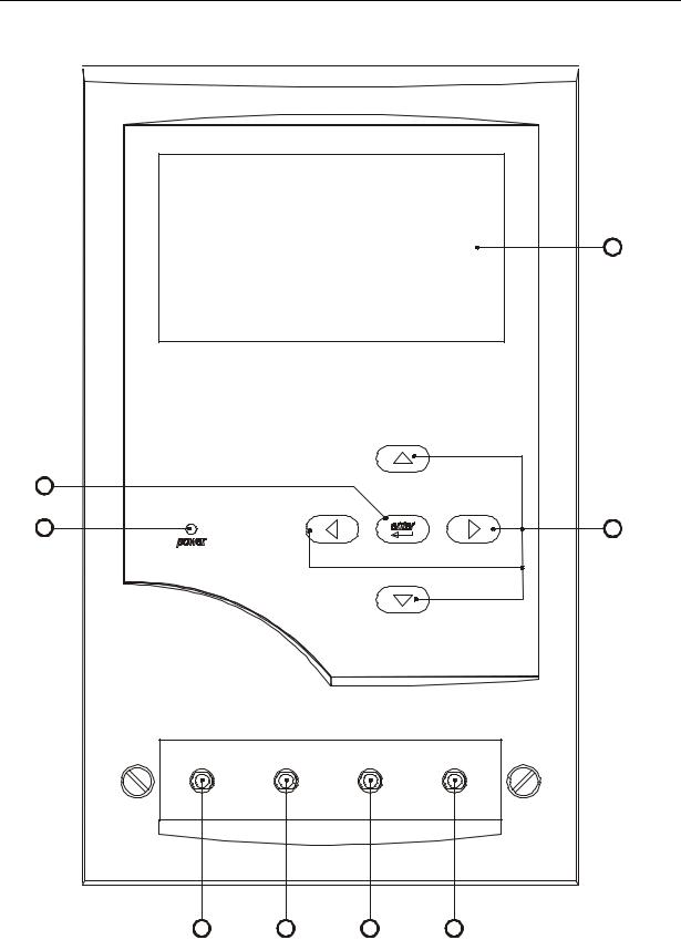
Front Panel Description
1.Liquid Crystal Display-240 dot (W) x 128 (H). Graphic and Alphanumeric. With backlight.
2.Up, Down, Right and Left key-pad switches
3.Enter keypad.
4.Power ‘ON’ Indicator
5.Channel 1 Fluid ‘IN’ connector.
6.Channel 2 Fluid ‘IN’ connector.
7.Channel 3 Fluid ‘IN’ connector.
8.Channel 4 Fluid ‘IN’ connector.
2-2
Infusion Pump Analyzer 2
An Overview
Front Panel Layout Drawing
1
3
4 |
2 |
|
inlets |
|
|
channel 1 |
channel 2 |
channel 3 |
channel 4 |
5 |
6 |
7 |
8 |
2-3

IDA-4 Plus
Operators Manual
Rear Panel Description
9.Mains ON / OFF switch.
10.Three pin IEC mains inlet connection.
11.Twin fuses integral with mains connector.
12.Alarm Control port. 15 way. (for optional trigger interface).
13.Parallel Printer Port. 25 way Female. Configured in the same way as a PC Printer Port.
14.Bar Code Wand Port. 9 way Female.
Configured for HP Smart Wand (2400 Baud, n, 8, 1).
15.Computer RS232 Port. 9 way Female. Configured in the same way as PC COM Port.
16.Channel 4 Fluid ‘OUT’ connector.
17.Channel 3 Fluid ‘OUT’ connector.
18.PC AT keyboard Port. Configured for AT keyboards.
19.Channel 2 Fluid ‘OUT’ connector.
20.Channel 1 Fluid ‘OUT’ connector.
21.Carrying handle.
2-4

Infusion Pump Analyzer 2
An Overview
Rear Panel Layout Drawing
2-5

IDA-4 Plus
Operators Manual
2-6

Chapter 3
Operating Instructions
This chapter discusses and illustrates the method of connecting units under test and the various operational modes.
Connecting Infusion Pumps under Test
See Inlet Hose Connections and Outlet Hose Connections drawings.
The Inlet Hose Connection drawing on the next page shows a method of connecting the inlets from units under test together with a priming syringe, both connected via a 3-way tap.
This method is the only method that should be employed with this instrument.
The Outlet Hose Connection drawing on page 3 shows the drain hose connections from the unit to an open drainage collection vessel. Please note that the drain Fluid Outlets should each have an independent hose to the drainage vessel and should not be joined in any way.
Note: Infusion device measurement accuracy is also affected by the compliance of the infusion device and delivery tubes. This is because there is a momentary blockage of flow when the measurement transducer is emptied. The back-pressure created by these events could cause some of the flow to be diverted into the compliance of the infusion device. For most infusion devices, the effect is trivial (less than 0.5%), but with very soft connecting tubing and large air pockets in the device or tubing, it could be significant. The tubing between the infusion device and the IDA-4 Plus should therefore be fairly rigid and all air should be removed before starting each flow test. At high flow rates it may be desirable to increase the compliance of the inlet tubing (longer or softer tube) if the back pressure interferes with the occlusion sensing alarms in the infusion device.
3-1
Loading...