


5700A/5720A
Series II Multi-Function Calibrator
Operator Guide
PN 601648
May 1996
© 1996 Fluke Corporation, Inc.
All rights reserved. Printed in U.S.A. |
® |
Contents
What is in this Guide? ................................ |
2 |
Safety Summary ......................................... |
2 |
P Fuse and Line Voltage .......................... |
4 |
Basic Operation.......................................... |
5 |
A Short Calibration Exercise ....................... |
5 |
Warming up the Calibrator ..................... |
5 |
Exercise: Running dc Zero Calibration ........ |
6 |
Connecting a Meter................................ |
6 |
Applying a dc Voltage ............................ |
7 |
Checking the Calibrator Uncertainty ....... |
7 |
Exercise: Activating Error Mode ............. |
8 |
Checking the Meter’s Higher and Lower |
|
Ranges ..................................... |
8 |
Exercise: Applying an ac Voltage ........... |
9 |
Front Panel Features.................................. |
10 |
Output Display (Left Side) ...................... |
10 |
Control Display (Right Side) ................... |
10 |
Display Screen Saver............................. |
11 |
Front Panel Keys ................................... |
12 |
Front Panel Connectors ......................... |
21 |
Rear Panel Features .................................. |
23 |
Rear Panel Connectors .......................... |
23 |
Switches and Fuse Holder...................... |
26 |
Cable Recommendations............................ |
27 |
Connecting to a UUT (Unit Under Test) ...... |
28 |
Using Error Mode ....................................... |
35 |
Operating in Remote .................................. |
37 |
RS-232-C Interface Parameters.................. |
38 |
1
What is in this Guide?
The Operator Guide begins with safety information, a short meter calibration exercise for new users, then continues with a condensation of information from the Operator Manual. For complete information about the Calibrator’s features, functions, and operating procedures, refer to the Operator Manual.
Safety Summary
Warning
[
Lethal voltage may be present on the terminals. Observe all safety precautions in this guide.
To avoid electrical shock hazard, the operator should not electrically contact the OUTPUT HI or SENSE HI binding posts. During operation, lethal voltages of up to 1100V ac or dc may be present on these terminals.
Whenever possible, keep one hand away from the equipment to reduce the hazard of current flowing through vital organs of the body.
Symbols Marked on Equipment
[Warning - Risk of electric shock.
QGround Protective ground (earth) terminal.
PAttention Refer to the manual for information about this feature. This symbol appears on the rear panel ground terminal and by the fuse holder.
Use the Proper Fuse
To avoid fire hazard, use only the fuse specified on the line voltage selection switch label.
2
Safety Summary (cont.)
[Grounding the Calibrator
The Calibrator is a Safety Class I (grounded enclosure) instrument. The enclosure is grounded through the grounding conductor of the power cord. To avoid electrical shock, plug the power cord into a properly wired earth grounded receptacle before making any connections to the Calibrator terminals. A protective ground connection by way of the grounding conductor in the power cord is essential for safe operation.
[Do Not Remove the Cover
To avoid personal injury, do not remove the Calibrator cover. Do not operate the Calibrator without the cover properly installed. There are no user-serviceable parts inside the Calibrator, so there is no need to ever remove the cover.
3
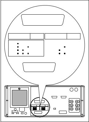
PFuse and Line Voltage
The correct fuse type for each voltage selection is indicated on the rear panel as shown in the following figure.
CAUTION FOR FIRE PROTECTION REPLACE ONLY
WITH A 250V FUSE OF INDICATED RATING.
VOLTAGE |
FUSE-F1 |
|
SELECTION |
||
|
|
100V |
S2 |
|
S3 |
|
S4 |
|
|
|
|
|
|
|
|
|
T 125A |
|
|
|
|
|
|
|
|
||
|
110V |
|
|
|
|
|
|
|
|
|
|
|
|
|
|
250V |
|
|
115V |
|
|
|
|
|
|
|
|
|
|
|
|
|
|
(SB) |
|
|
|
|
|
|
|
|
||
|
120V |
|
|
|
|
|
|
|
|
|
|
|
|
|
|
|
|
|
|
|
|
|
|
|
|
|
|
|
|
|
|
|
|
|
|
|
|
|
|
|
|
|
|
|
|
|
|
|
|
|
|
|
|
VOLTAGE |
FUSE-F1 |
|
SELECTION |
||
|
200V |
S2 |
|
S3 |
|
S4 |
|
|
|
|
|
|
|
|
|
|
T 125A |
|
|
|
|
|
|
|
|
|
|
|
||
220V |
|
|
|
|
|
|
|
|
|
|
|
|
|
|
|
250V |
|
|
|
230V |
|
|
|
|
|
|
|
|
|
|
|
|
|
|
|
(SB) |
|
|
|
|
|
|
|
|
|
|
|
||
240V |
|
|
|
|
|
|
|
|
|
|
|
|
|
|
|
|
|
|
|
|
|
|
|
|
|
|
|
|
|
|
|
|
|
|
|
|
|
|
|
|
|
|
|
|
|
|
|
|
|
|
|
|
|
|
|
|
|
|
|
CAUTION FOR FIRE PROTECTION REPLACE ONLY
WITH A 250V FUSE OF INDICATED RATING.
VOLTAGE |
|
FUSE-F1 |
VOLTAGE |
|
FUSE-F1 |
||
SELECTION |
SELECTION |
||||||
S2 |
S3 |
S4 |
|
S2 |
S3 |
S4 |
|
100V |
|
|
T 125A |
200V |
|
|
T 125A |
110V |
|
|
250V |
220V |
|
|
250V |
115V |
|
|
(SB) |
230V |
|
|
(SB) |
120V |
|
|
|
240V |
|
|
|
Line Power Label and Switch Locations
4
Basic Operation
To set the output, simply press the following sequence of keys to select an output function and amplitude:
[numeric keys] [multiplier] [function] E O
For example, to set the output to 10 mV dc, press:
1 0 m V E O
To set an ac output, press the following additional keys:
[numeric keys] [multiplier] H E
For example, to change the present 10 mV dc to 10 mV ac @ 1.8 kHz, press:
1 . 8 K H E
To change the output back to dc, press:
0 H E
or
+ E
A Short Calibration Exercise
If you are not familiar with the Calibrator, you will find that the following exercise quickly teaches you some important front panel operations.
Warming up the Calibrator
When you first turn the Calibrator on, you should let it warm up for 30 minutes. This ensures that the Calibrator meets or exceeds its specifications.
5
Exercise: Running dc Zero Calibration
DC Zero is a brief internal process that removes offset errors. The specifications require that you run dc Zero at least every 30 days.
To run dc Zero, press the following sequence of softkeys:
Setup Menus Cal Zero
Press any key, then press Ptwice to return to normal operation.
Connecting a Meter
Typical connections for handheld and benchtop meters are shown on the next page. The diagrams show the use of Fluke Model 5440-7002 Low Thermal Cables. Other types of cable may be used for this exercise. To connect either type of meter, proceed as follows:
1.Verify that the Calibrator is on, and is in standby mode (STANDBY indicator lit). If the Calibrator is not in standby, press r.
2.Set the meter to the lowest range that reads 10V dc.
3.Connect the shield lead (if your cables are shielded) to V GUARD on the Calibrator.
4.Verify that both Xand xare off. Press them if they are lit.
5.Connect the meter input LO to the Calibrator OUTPUT LO.
6.Connect the meter input HI to the Calibrator OUTPUT HI.
6

Exercise: Connecting a Meter (cont.)
DMM |
Calibrator |
: OFF |
: OFF |
EX SNS |
EX GRD |
OUTPUT SENSE
|
|
|
|
V Ω A |
VΩ |
|
|
|
|
HI |
|
|
HI WIDEBAND |
|
|
|
LO |
|
|
LO |
|
|
|
HI |
|
|
|
10A |
VΩ |
|
|
AUX |
GUARD GROUND |
|
300mA |
|
CURRENT |
||||
|
|
|
||||
|
|
|
|
|
||
|
COM |
|
|
|
|
|
|
NC |
|
|
|
|
|
|
|
EX SNS |
: OFF |
: OFF |
Calibrator |
|
|
|
EX GRD |
|
|||
|
|
|
|
|
||
|
|
|
|
OUTPUT SENSE |
||
|
|
|
|
V Ω A |
VΩ |
|
|
|
|
|
HI |
|
WIDEBAND |
|
|
|
|
|
HI |
|
INPUT |
|
|
|
LO |
|
|
|
|
|
|
|
LO |
|
|
|
|
|
|
|
|
|
|
|
|
HI |
|
|
|
|
|
|
AUX GUARDGROUND |
||
|
DMM |
|
|
CURRENT |
|
|
|
NC |
|
|
|
|
|
|
|
|
|
|
|
|
Applying a dc Voltage
Apply 10V dc to the meter by pressing the following sequence of keys:
10VEO
Checking the Calibrator Uncertainty
Press s. The total uncertainty for the 10V you are applying to the meter is displayed on the Control Display (the large dot-matrix display on the right side of the front panel). This number depends on the setting of the calibration cycle and specification confidence level in a setup menu.
Press Pto clear the uncertainty display.
7
Exercise: Activating Error Mode
Chances are the meter reads something other than exactly 10V. To quickly check the error of the meter, turn the rotary knob to obtain a meter reading of exactly 10V, and read the error off the Control Display.
Turning the knob is all it takes to activate error mode. When you turn the knob, the least significant digit is highlighted. This digit changes as you turn the knob. To change a higher order digit, thereby speeding up the adjustment rate, press <.
The error on the Control Display is a combination of offset, scale, and linearity errors. You can view component parts of the error by pressing oand
S.
Checking the Meter’s Higher and Lower Ranges
To check the meter error at 100V dc, first set the meter range (if applicable) to the lowest range that reads 100V. Press YO. This sets a new reference equal to ten times the previous reference of 10V dc. (Pressing Owas necessary because the Calibrator goes into standby when it crosses the safety threshold from below 22V to over 22V.) Turn the rotary knob to re-activate error mode and determine the meter error at 100V.
Now press ZZ. Set the meter range switch (if applicable) to the lowest range that reads 1V.
To end the error mode session, press E. This recalls the reference value and exits error mode.
Press r to set the output to 0 mV dc in standby.
8
Exercise: Applying an ac Voltage
There is no “ac mode” switch on the Calibrator. You change a dc output to ac by entering a frequency through the keypad and pressing
E.
To test the meter at 10V at 1 kHz, set the meter to read 10V ac, press 10V, then 1K HEO. Adjust the rotary knob for a reading on the meter of exactly 10V.
To test the meter’s flatness, press a. The 0.1 Hz digit is highlighted. Press <four times. Turn the knob to change the 1 kHz digit until the Calibrator is set to 10 kHz. Press aand turn the knob again to check the meter’s accuracy at 10 kHz. Each time you change the frequency, you need to wait for the Calibrator output to settle (the “u” annunciator will go out).
This ends the front panel exercise. To zero the output and go to standby, press r.
9
Front Panel Features
Following is a brief description of the Calibrator’s front panel features.
Output Display (Left Side)
Shows output amplitude and frequency. The top line shows the active output value in up to eight digits, plus a polarity sign. The bottom line shows output frequency in five digits. Annunciators below the amplitude line on the output display indicate the following active conditions:
OPERATE |
Lit when an output is active at the |
|
binding posts or auxiliary amplifier. |
STANDBY |
Lit when the Calibrator is in standby. |
ADDR |
Lit when the Calibrator is addressed |
|
over the IEEE-488 interface. |
ØLCK |
Lit when the Calibrator output is |
|
phase locked to a signal at the rear |
|
panel PHASE LOCK connector. |
ØSHF |
Lit when the Calibrator output has a |
|
programmed phase difference with a |
|
signal at the real panel VARIABLE |
|
PHASE OUT connector. |
u(Unsettled) Lights when the output is changed, and remains lit until the output settles to within specification.
Control Display (Right Side)
Shows data entries, UUT error adjustments, softkey labels, and other prompts and messages. Each softkey label identifies the functions of the softkey that appears directly below it. All of the softkey labels that appear on the display at once are referred to as a menu. When you access the function provided through the softkeys, you open up other menus, containing new softkey labels.
10
 Loading...