

Page 1
USER INSTRUCTIONS
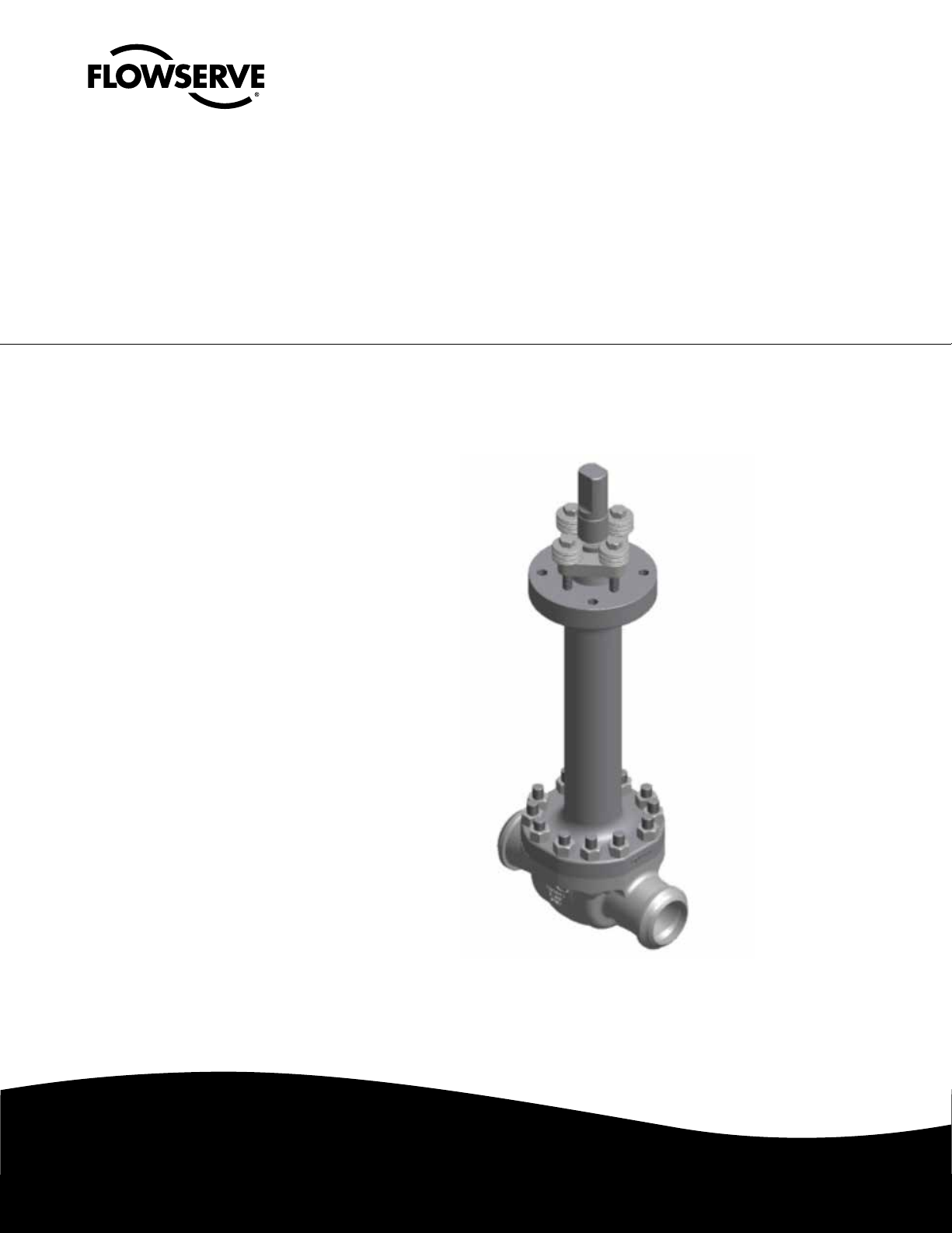
McCANNA CryoSeal® Ball Valves
FCD MMENIM2007-01-AQ – 04/15
Installation
Operation
Maintenance
Experience In Motion
Page 2

McCANNA CryoSeal® Ball Valves FCD MMENIM2007-01-AQ – 04/15
Contents
1 Introduction 3
1.1 Purpose 3
1.2 User Safety 3
2 Installation Instructions 4
2.1 General 4
2.2 Flanged End Valves 4
2.3 Weld End Valves 4
2.4 Valves with Vented Cavity Relief 5
3 Periodic Inspection and Adjustment 6
3.1 General 6
3.2 Stem Seal Adjustment 6
3.3 Bonnet Gasket Bolting Re-Tightening 7
3.4 Correcting Through Leakage –Soft Seated Valves 7
3.5 Other Specially Prepared Valves 7
4 Disassembly 8
4.1 Disassembly Instructions 8
4.2 Cleaning, Inspection, Lubrication Instructions 9
5 Reassembly 10
5.1 Reassembly Instructions 10
5.2 Standard Valves 10
6 Torque Charts 14
2
Page 3

1
McCANNA CryoSeal® Ball Valves FCD MMENIM2007-01-AQ – 04/15
Introduction
1.1 Purpose
This Installation, Operation and Maintenance Manual explains how to install and maintain McCANNA
CryoSeal
is provided.
®
ball valves. Information on installation, disassembly, reassembly, lubrication, and parts
1.2 User Safety
Safety notices in this manual detail precautions the user must take to reduce the risk of personal injury
and damage to the equipment. The user must read and be familiar with these instructions before
attempting installation, operation, or maintenance. Failure to observe these precautions could result in
serious bodily injury or death, damage to the equipment, warranty void, or operational difficulty.
Safety notices are presented in this manual in three forms:
a WARNING: Refers to personal safety. Alerts the user to potential danger. Failure to follow
warning notices could result in personal injury or death.
a CAUTION: Directs the user’s attention to general precautions that, if not followed, could result in
personal injury and/or equipment damage.
NOTE: Highlights information critical to the user’s understanding of the valve's installation and
operation.
flowserve.com
3
Page 4

2
McCANNA CryoSeal® Ball Valves FCD MMENIM2007-01-AQ – 04/15
Installation
2.1 General
McCANNA Cryoseal valves may be installed up to 45° from the vertical position. These valves are
unidirectional due to the need for cavity relief and must be installed in the correct orientation.
Installation methods and procedures should follow good industry practice, such as contained in
MSS-SP-92, or similar document.
a CAUTION: Check adjuster nut and bonnet fastener torques prior to testing or installation, and
re-tighten as needed (see tables 2 & 3). These fasteners may loosen during shipment, which
could result in external leakage.
a WARNING: Do not attempt any maintenance of these valves while in operation or under
pressure. Actuated valve air and/or electrical power supplies must be locked off and isolated
prior to any maintenance work. Failure to do so may result in significant equipment damage,
hazardous material discharge, or serious personal injury.
2.2 Flanged End Valves:
Flanged end valves are to be bolted in line to companion flanges of the same pressure class and facing
as the valve flanges, using the proper size and pressure class flange gaskets. Flowserve does not
provide companion flanges or flange gaskets. Flange bolt torquing should follow proper tightening
sequence outlined in Figure 6 on Page 13.
2.3 Weld End Valves:
2.3.1 Before installing weld end valves in line, remove bonnet, ball, and seats. Protect parts from
dirt or damage while out of valve, especially the seating surfaces in the body. Be very careful
to avoid heat distortion of the valve body during welding. A spare bonnet gasket has been
provided and should replace the original gasket during reassembly.
4
Page 5
McCANNA CryoSeal® Ball Valves FCD MMENIM2007-01-AQ – 04/15
2.3.2 If necessary, valves may be welded in line without disassembly, however special precautions
must be taken. The valve should be in the open position during welding and remain open until
it cools to ambient temperature. Welding procedures should be followed by qualified personnel
and in accordance with Section IX of ASME Boiler Pressure Vessel Code. The critical temperature areas (shown in Figure 1) should not exceed 350° F.
a WARNING: Do not attempt any welding on in-line valves under pressure.
2.3.3 When more than one weld is required for each end, the weld passes should alternate from end
to end until the welds are completed.
After the valve has cooled, the bonnet fasteners must be re-torqued to the recommended torque
value (shown in Table 3). When possible, a final seat test should be performed before placing
the valve into service.
Figure 1. Critical Weld Areas
CRITICAL TEMPERATURE AREAS
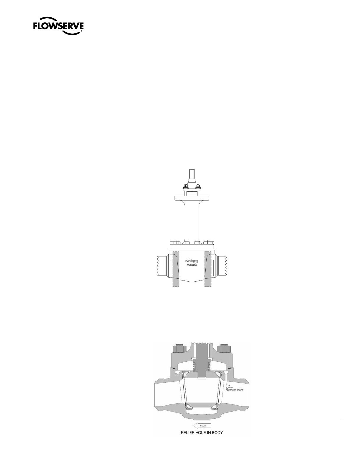
2.4 Valves with Vented Cavity Relief:
2.4.1 Install vented valves with the arrow on the body pointed in the direction of normal flow. (Figure 2)
Figure 2. Cavity Relief
5
flowserve.com
Page 6

3
McCANNA CryoSeal® Ball Valves FCD MMENIM2007-01-AQ – 04/15
Periodic Inspection and Adjustment
3.1 General
3.1.1 Good operating and maintenance procedures include periodic inspection of valves and other
piping system components to ensure that they are operating properly. Inspection schedules
must be determined by individual user, but as a minimum should consist of visually examining
valves for external leakage, and making adjustments as necessary.
a WARNING: Do not attempt any maintenance of these valves while in operation or under
pressure. Actuated valve air and/or electrical power supplies must be locked off and isolated
prior to any maintenance work. Failure to do so may result in significant equipment damage,
hazardous material discharge, or serious personal injury.
3.2 Stem Seal Adjustment
3.2.1 Stem seal leakage must be stopped immediately to avoid damage to the valve stem seals, stem
or bonnet, as well as possible contamination of the surrounding area. Tightening the adjuster
bolts (see Figure 3) can most often eliminate stem seal leakage. Tighten adjuster bolts by
turning each clockwise ¼ turn at a time until the torque value (given in Table 2) is reached.
3.2.2 If stem leakage continues, disassemble valve and replace stem seal set (see Disassembly/
Reassembly sections).
a CAUTION: Do not overtighten the adjuster bolts. Packing friction may increase excessively,
making the valve difficult or impossible to operate.
6
Page 7

McCANNA CryoSeal® Ball Valves FCD MMENIM2007-01-AQ – 04/15
3.3 Bonnet Gasket Bolting Re-tightening
3.3.1 Bonnet gasket leakage must be stopped immediately to avoid damage to the valve body/
bonnet joint surfaces, and contamination of the surrounding area. Tighten bonnet bolting to the
torque values specified (in Table 3) following the sequence shown in Figure 6. Also, If leakage
continues, remove valve bonnet and replace bonnet gasket (see Disassembly/ Reassembly
sections).
3.3.2 Valves which become difficult to operate or stuck, or show excessive seat (through valve)
leakage, should be disassembled and inspected for internal damage from corrosion or wear,
and repaired as necessary (see Disassembly/Reassembly sections).
3.4 Correcting Through Leakage – Soft Seated Valves
The wedge seat design permits soft-seated valves to be self-adjusting for seat wear, and thereby extend
service life. In many instances where through-leakage is discovered, it may be corrected by simply
cycling the valve open to closed several times, to allow the seats to “snug down” into the wedge. Soft
seats are also more prone to damage from particles or abrasives in the flow stream. When through
leakage cannot be reduced or eliminated by cycling, the valve should be taken out of service and disassembled for inspection and possible replacement of seats (see Disassembly/ Reassembly sections).
3.5 Other Specially Prepared Valves
Some valves with special preparation such as for Oxygen, Chlorine, Vacuum or other special services
may have special maintenance instructions. See any special instructions which were supplied with the
valve shipment.
NOTE: These instructions may also be obtained from your McCANNA distributor.
flowserve.com
7
Page 8

4
McCANNA CryoSeal® Ball Valves FCD MMENIM2007-01-AQ – 04/15
Disassembly
4.1. Dissassembly
a WARNING: Do not attempt any maintenance of these valves while in operation or under
pressure. Actuated valve air and/or electrical power supplies must be locked off and isolated
prior to any maintenance work. Failure to do so may result in significant equipment damage,
hazardous material discharge, or serious personal injury.
4.1.1. Refer to CryoSeal Parts Identification (Figure 3) for this section.
4.1.2. Make sure valve is in full open position, and remove actuation assembly (handle, gear, or power
actuator).
a CAUTION: Do not try to remove ball while in closed position. Damage to ball sealing surfaces
will result if this is attempted.
4.1.3 Remove bonnet nuts. Loosen evenly; bonnet will lift due to internal spring.
4.1.4 Remove bonnet assembly, spring, and bonnet gasket. Place bonnet assembly on clean work
surface.
4.1.5 Loosen nuts on adjuster bolts evenly and remove nuts, Belleville washers, adjuster rocker, and
gland follower.
4.1.6 Slide stem out through the inner side of the bonnet.
a CAUTION: Do not force stem out of bonnet as severe damage may result. Be careful not to
scratch the stem throughout disassembly. There is a washer present at the bottom of the stem.
NOTE: Stem has a shoulder which prevents blowout under pressure.
4.1.7 Remove o-ring cartridge, stem seals, metal washer and lipseal from bonnet taking care not to
scratch the bonnet bore surface.
4.1.8 Insert a large screwdriver or similar tool into the oval slot of the ball and loosen by moving the
screwdriver in a direction 90° to the pipe line until the screwdriver rests against the valve body
(cover only gasket edge).
4.1.9 Carefully lift ball and seats upward by pushing down on the screwdriver until they can be
removed by hand.
8
NOTE: Avoid marring bonnet gasket surfaces and ball surfaces
4.1.10. Clean and inspect all parts for wear or damage. Pay particular attention to gasket and seating
surfaces, ball surface, travel stop and soft parts.
Page 9

Figure 3. Exploded View
McCANNA CryoSeal® Ball Valves FCD MMENIM2007-01-AQ – 04/15
flowserve.com
9
Page 10

McCANNA CryoSeal® Ball Valves FCD MMENIM2007-01-AQ – 04/15
4.2 Cleaning, Inspection, and Lubrication Instructions
4.2.1 After disassembly, discard bonnet gasket and stem seals (if removed). Gaskets and seals are
not re- usable. Carefully clean and inspect all parts for wear or damage, paying particular
attention to seating/sealing surfaces on ball and seats, stem journal and bonnet bore, and body/
bonnet gasket areas.
4.2.2 Damaged or badly worn parts should be replaced using only parts or repair kits supplied by
Flowserve. Valve parts considered for repair should be evaluated by an Authorized McCANNA
Repair Center to determine if repair is possible.
NOTE: Body seat surfaces are lapped flat, and must be checked for flatness and cleanliness before
reassembly. If re-lapping is required, contact the nearest Authorized McCANNA Repair Center.
4.2.3 Lubrication of valve parts to aid assembly and initial operation is recommended, when
permitted by service and operating conditions. The lubricant used must be compatible with the
intended service (see Table 1 below for recommended lubricants). If necessary, valve internal
wetted parts may be assembled without lubrication.
Table 1 - Lubricants
Recommended Lubricants
Stem Krytox
O-Rings / Stem Packing Krytox
Ball / Seats Molykote 321
Studs / Nuts (Bonnet and Adjuster) Never-Seez
4.2.4 Lubricants are to be applied sparingly; a thin wipe is sufficient. Do not apply lubricants with a
brush or other means. Excessive lubricant on the ball, seat, or in the stem bore can affect valve
performance and should be removed from the valve. If lubricant build-up or caking is visible on
the ball or seats, too much has been used.
10
Page 11

5
McCANNA CryoSeal® Ball Valves FCD MMENIM2007-01-AQ – 04/15
Reassembly
Refer to CryoSeal Parts Identification (Figure 3) for this section.
NOTE: Lubricating this valve during assembly is recommended as described in preceding steps 4.2.3
and 4.2.4 Assembly will be easier, the valve operating torque will be lower, and the valve seal will be
tighter. The lubricant selected must be compatible with the intended valve service. It is also possible to
assemble without the use of lubricants if required by the service conditions.
Standard valves
5.1 Install adjuster studs into the top of the bonnet. Anti-seize lubricant is suggested to be applied
to the threads. These are the holes located closest to the packing bore. Depending on valve size
there will be 2 or 4 adjuster studs.
5.2 Lightly lubricate the area of the stem that will be in contact with the O-rings and stem seals.
Also lubricate the O-rings and stem seals. This should be a very light layer of lubrication.
5.3 Install the lip seal into the packing bore at the top of the bonnet. The o-ring shall be at the top of
the lip seal. See Figure 4 for correct orientation.
5.4 Install packing into packing bore. Install bottom rope first, then each additional piece as it was
stacked up. If there are cuts present in the graphoil rings, these cuts are to be placed 180°
apart. Install top packing rope.
Figure 4. Stem Seal Assembly
flowserve.com
11
Page 12

McCANNA CryoSeal® Ball Valves FCD MMENIM2007-01-AQ – 04/15
5.5 Install O-rings and back-up rings into metal cartridge. Back up rings have a flat side and concave
side. Concave side is to be facing the o-ring. Ensure that back-up rings do not become twisted
during assembly. There will be 4 O-rings in a cartridge (2 on the OD and 2 on the ID). Install the
smaller O-rings and back-up rings on the inner diameter of the cartridge, and the larger O-rings
and back-up rings on the outer diameter of the cartridge.
5. 6 Insert o-ring cartridge into packing bore. O-rings are to be at the bottom of each groove, with a
back-up ring on top of each o-ring. See Figure 4 for correct orientation.
5. 7 Install the gland follower into the packing bore. This follower has a step with a smaller inner
diameter on one side. The step should be placed at the top.
5. 8 Place adjuster onto top adjuster studs. The rounded rocker portion of the adjuster will be in
contact with the gland follower.
5. 9 Install Belleville washers on adjuster studs. An equal number of washers will be on each adjuster
stud. Pairs of Belleville washers are to be installed cup-to-cup. See Figure 5 for correct orientation
Figure 5. Belleville Washer
12
5. 10 Tighten nuts onto adjuster bolts finger tight. This is not to compress the packing, but only to hold
it in place during stem insertion.
5. 11 Slide the lower thrust bearing washer onto the stem. This will be above the blowout proof step on
the stem.
5. 12 Insert stem into bonnet, taking care not to scratch the stem or damage the packing. Ensure that
when the bonnet is placed on the body, the stem will be in the open position.
5. 13 Torque adjuster nuts to proper torque value specified in Table 2.
Table 2 - Minimum Torque Requirements for Adjuster Bolts
Recommended Torque (ft-lbs)
Regular Port Valve Size Full Port Valve Size Class 150/300 Class 600
1.5 0.5, 0.75, 1 15 15
2 1.5 15 15
3 2 15 15
4 3 40 40
6 4 40 40
8 6 40 40
Page 13

McCANNA CryoSeal® Ball Valves FCD MMENIM2007-01-AQ – 04/15
5. 14 Assemble plastic seat inserts into seal rings. Place a PTFE seat seal in the back of each seat. Lightly
lubricate ball sealing surface and seat sealing surfaces.
5. 15 Place seats in position on ball so that seats are aligned with the ball flow passage, with the ball slot
facing upwards. Holding ball and seats in position, lift as a unit and carefully lower into valve body,
lining up seat backs with body seat surfaces. Carefully align the ball stem slot so that it is perpendicular to the body flow passage and the top flat of the ball is parallel to the bonnet flange.
5. 16 Lubricate bonnet fasteners (studs & nuts) per Table 1.
5. 17 Place a new bonnet gasket in the machined groove in the body. Place spring on ball, centered on
stem slot.
5. 18 Place bonnet assembly on body, aligning stem tang with spring and ball slot, and bonnet bolt holes
with body studs. Carefully press down on bonnet, making sure bonnet gasket register is properly
aligned with body bore. Spring resistance will be felt; this is normal. Continue pressing down, taking
care not to damage gasket, until studs extend through the bonnet enough to engage nuts. Holding
bonnet in place, thread nuts on to studs and tighten finger tight. Follow the bolt tightening sequence
(Figure 6).
Figure 6. Bolting Sequence
5. 19 Tighten bonnet bolting evenly to the torque values (Table 3) following the bolt tightening sequence
(Figure 6). Manually cycle valve several times to verify proper operation. Reinstall actuation (handle,
gear, or actuator). Testing before reinstallation is recommended.
Table 3 - Bonnet Bolting Torques
Torque (ft-lbs)
Regular Port Valve Size Full Port Valve Size Class 150/300 Class 600
1.5 0.5, 0.75, 1 40 65
2 1.5 95 95
3 2 195 195
4 3 345 345
6 4 345 445
8 6 665 795
13
flowserve.com
Page 14

6
Cryogenic Valve, Kel-F Seats 0.5" thru 2" Full Port, 3" Std. Port
300 3600
McCANNA CryoSeal® Ball Valves FCD MMENIM2007-01-AQ – 04/15
Torque Charts
FP SP
in
(mm)
250 3000
200 2400
150 1800
100 1200
50 600
0
ft-lbs
in-lbs
Torque
2” 3”
(50) (80)
1.5” 2”
(40) (50)
.5”, .75”, 1” 1.5”
(15, 20, 25) (40)
0 200 400 600 800 1,000 1,200 1,400
Differential Pressure (PSI)
14
Page 15

McCANNA CryoSeal® Ball Valves FCD MMENIM2007-01-AQ – 04/15
Cryogenic Valve, Kel-F seats 3" thru 6" Full Port, 8" Std. Port
400 48000
3000 36000
2000 24000
1000 12000
0
ft-lbs
Torque
0 200 400 600 800 1,000 1,200 1,400
in-lbs
Differential Pressure (PSI)
FP SP
6” 8”
(150) (200)
4” 6”
(100) (150)
3” 4”
(80) (100)
in
(mm)
flowserve.com
15
Page 16

Flowserve Flow Control (UK)
Burrell Road
Haywards Heath
West Sussex United Kingdom RH16 1TL
Phone: +44 1444 314400
Fax: +44 1444 314401
Flowserve Corporation
Flow Control Division
1978 Foreman Drive
Cookeville, Tennessee 38501 USA
Phone: +931 432 4021
Fax: +931 432 5518
Flowserve Pte Ltd
No. 12 Tuas Avenue 20
Singapore 638824
Phone: +65 6879 8900
Fax: +65 6862 4940
Flowserve Flow Control Benelux BV
Rechtzaad 17
4703 RC Roosendaal NB
Netherlands
Phone: +31 165 598 800
Fax: +31 165 555 670
Flowserve Australia Pty Ltd
Flow Control Division
14 Dalmore Drive
Scoresby, Victoria 3179
Australia
Phone: +61 3 9759 3300
Fax: +61 3 9759 3301
FCD MMENIM2007-01-AQ Printed in USA. April 2015
To find your local Flowserve representative:
For more information about Flowserve Corporation, visit
www.flowserve.com or call USA 1 800 225 6989
Flowserve Corporation has established industry leadership in the design and manufacture of its products. When properly selected, this Flowserve product is designed to perform its intended
function safely during its useful life. However, the purchaser or user of Flowserve products should be aware that Flowserve products might be used in numerous applications under a wide
variety of industrial service conditions. Although Flowserve can (and often does) provide general guidelines, it cannot provide specific data and warnings for all possible applications. The
purchaser/user must therefore assume the ultimate responsibility for the proper sizing and selection, installation, operation, and maintenance of Flowserve products. The purchaser/user
should read and understand the Installation Operation Maintenance (IOM) instructions included with the product, and train its employees and contractors in the safe use of Flowserve
products in connection with the specific application.
While the information and specifications contained in this literature are believed to be accurate, they are supplied for informative purposes only and should not be considered certified or as
a guarantee of satisfactory results by reliance thereon. Nothing contained herein is to be construed as a warranty or guarantee, express or implied, regarding any matter with respect to this
product. Because Flowserve is continually improving and upgrading its product design, the specifications, dimensions and information contained herein are subject to change without notice.
Should any question arise concerning these provisions, the purchaser/user should contact Flowserve Corporation at any one of its worldwide operations or offices.
© 2015 Flowserve Corporation, Irving, Texas, USA. Flowserve is a registered trademark of Flowserve Corporation.
Flowserve Flow Control GmbH
Rufolf Plank Str. 2
D-76275 Ettlingen
Germany
Phone: +49 7243 103 0
Fax: +49 7243 103 222
Flowserve do Brasil Ltda
Rua Tocantins, 128 - Bairro Nova Gerti
São Caetano do Sul,
São Paulo 09580-130 Brazil
Phone: +5511 4231 6300
Fax: +5511 4231 6329 - 423
Flowserve Corporation
Unit 01\02\06\07 9F
China Fortune Tower
No. 1568, Centur y Avenue, Pudong
Shanghai China 200122
Phone: +86 21 38654800
Fax: +86 21 50811781
Flowserve Corporation
No. 35, Baiyu Road
Suzhou Industrial Park
Suzhou 215021, Jiangsu Province, PRC
Phone: +86-512-6288-1688
Fax: +86-512-6288-8737
Flowserve China
Hanwei Building
No. 7 Guanghua Road
Chao Yang District
1000004 Beijing
CHINA
Phone: +86 (10) 6561 1900
Fax: +86 (10) 6561 1899
flowserve.com
 Loading...