


MFT-KAPEX
Instruction manual
Page 3 - 11
IMPORTANT: Read and understand all instructions before
using.
Guide d’utilisation
Page 13 - 21
IMPORTANT: Lire et comprendre toutes les instructions
avant de démarrer les travaux.
Manual de instrucciones
Pagina 22 - 31
IMPORTANTE: Lea y comprende todas las instrucciones
antes de usar.
475235_003
Instruction manual
Guide d’utilisation
Manual de instrucciones
MFT/3 MFT/KAPEX

2
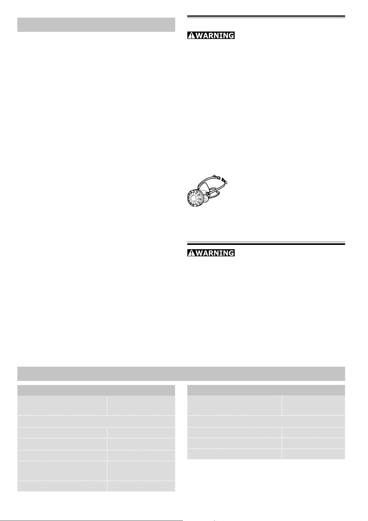
Table of Contents
Technical data 3
Symbols 4
Design 4
Intended use 4
MFT/3: Setting up and assembly 5
Step 1: Setting up 5
Step 2: Trim splinter guard 5
Step 3: Setting up the guide rail support 6
Step 4: Attaching the guide rail 7
Step 5:
Step 6: Calibrating angle 8
Step 7: Adjusting the pre-set profi le set-
Step 8: Adjusting the guide rail in rela-
Step 9: Adjusting the cutting depth for
MFT/KAPEX: Mounting the KAPEX 10
Attaching the pre-set profi le setting
rail 7
ting rail 8
tion to the workpiece 9
sawing [Fig. 11] 9
Health hazard by dust
Various dust created by
power sanding, sawing, grinding, drilling
and other construction activities contains
chemicals known (to the State of California) to cause cancer, birth defects or other reproductive harm. Some examples of
these chemicals are:
• Lead from lead-based paints,
• Crystalline silica from bricks and cement
and other masonry products,
• Arsenic and chromium from chemically-
treated lumber.
The risk from these exposures varies, depending on how often you do this type of
work.
To reduce your exposure to these
chemicals work in a well ventilated area and use approved
safety equipment, such as dust
masks that are specially designed to fi lter out
microscopic particles.
Maintenance 10
Turning the perforated top 10
Accessories, tools 10
Warranty 11
The multifunction table offers a wide range of application options! To fi nd out more L
about possible machine applications, order the MFT application manual on the internet.
INJURY, USER MUST READ AND UNDERSTAND INSTRUCTION MANUAL.
TO REDUCE THE RISK OF
Technical data
MFT/3
Bench dimensions
(width x length)
Bench height
1157 x 773 mm
MFT/KAPEX
Bench dimensions
(width x length)
Bench height
869 x 581 mm
- with foldaway legs 900 mm
- without foldaway legs
max. working width 700 mm
max. workpiece thickness
Weight 28 kg
180 mm
78 mm
- with foldaway legs 790 mm
- without foldaway legs 180 mm
Weight 18 kg
3
Symbols
Intended use
Warning of general danger
Read the Operating Instructions/
Notes!
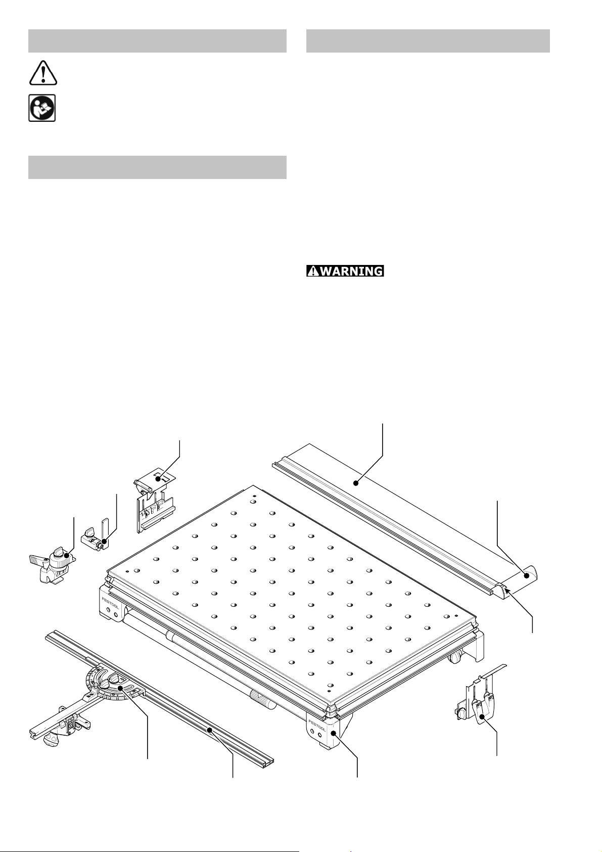
Design
MFT/3 and MFT/KAPEX
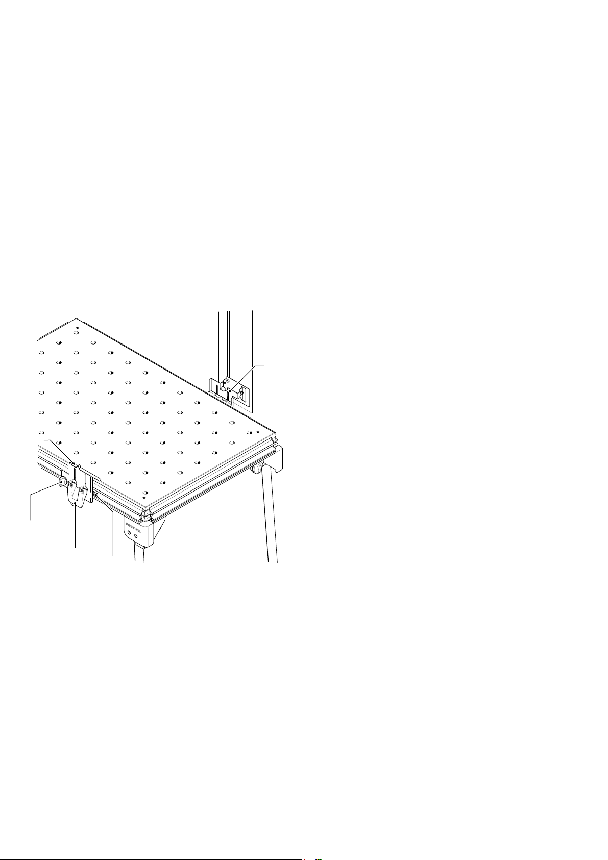
[1-1] Bench consisting of: profi le frame,
corner feet, perforated top, foldaway legs
MFT/3 only
[1-2] Support unit
[1-3] Guide rail FS 1080
[1-4] Swivel unit
[1-5] Pre-set profi le setting rail and
[1-6] Stop ruler
The multifunction table MFT/3 is designed for safe, accurate sawing and
routing in combination with Festool electric power tools.
The clamping systems included in the accessories programme enable the user to
attach workpieces securely to the worktop. The base becomes a work bench for
various tasks such as planing, sanding,
carving, etc.
The multifunction table MFT/KAPEX was
specially designed for attaching the
KAPEX KS 120.
The user bears the responsibility for damage and accidents caused
by improper use.
[1-7] Additional clamp for stop ruler
[1-8] Stop fl ag MFT/3-AR
[1-9] Defl ector
1-4
1-4
1-8
1-8
1-7
1-7
1-3
1-3
1-9
1-9
1
1-10
1-10
1-5
1-5
1-6
1-6
4
1-1
1-2
MFT/3:
Setting up and assembly
Accessory attachments can be secured at
different points on the multifunction table
to enable different working positions.
In the standard working position, the user
stands along one side of the bench [Fig. 2].
In these operating instructions, this side of
the bench is referred to as the "front".
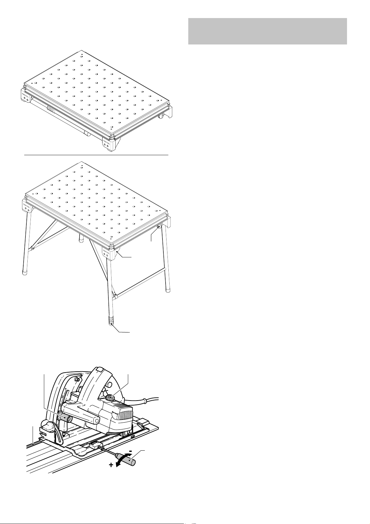
Step 1: Setting up
Take the table out of the box. Screw on
the knobs [2-3] until the stop is reached.
Unfold the foldaway legs and tighten the
knobs on the joints to secure. Turn the end
cap [2-1] on the right to adjust the length
of the leg and compensate for an uneven
fl oor surface.
2
3-1
3-2
2-2
2-1
2-3
NOTE: The corner feet [2-2] are fi tted
with rubber caps so that the bench stands
securely when the legs are folded away.
Step 2: Trim splinter guard
Now you are ready to set up the guide rail
system. The fi rst thing to do is to trim the
splinter guard [3-4] of the guide rail using
your Festool plunge-cut saw.
3-4
3-3
3
Place your saw on top of the guide rail
and tune it to the track on the rail using a
screwdriver [3-3] to loosen or tighten the
front and back set screws so that there
is no play between the sole plate of the
saw and he raised portion of the guide
rail. However, make sure that the saw still
glides smoothly on top of the guide rail.
5
REAR
REAR
FRONT ( Working side)
4-4
Adjust the speed of the saw [3-2] to a
setting of „6“ (maximum speed). Set the
depth of cut, using the depth stop adjustment [3-1], to 8 mm (5 mm for the thickness of the guide rail plus 3 mm cutting
depth) and cut the splinter guard along
the full length without interruption.
For trimming the splinter guard it is best
to use some sort of backing piece, such as
plywood or fi berboard.
The edge of the splinter guard now corresponds exactly to the cutting edge.
Step 3: Setting up the
guide rail support
The table comes from the factory with two
stops [4-2, 4-4] pre-set on the long sides
of the profi le frame, opposite each other.
These are recommended working positions
for the support unit [4-2] and swivel unit
[4-4].
4-5
4-1
4-2
4-3
FRONT ( Working side)
4
NOTE: During transport it is possible that
the set screws holding the stops may have
loosened. If this is the case, you will have
to position and retighten the registering
stops. Facing the front of the table, the
measurement is 8 3/4’’ from the side face
of the profi le frame at the right side of the
table. Facing the rear, the stop is approximately 7 2/3’’ from the side face at the left
side of the table.
The swivel unit [4-4] is mounted on the
rear long side, the support unit [4-2] on
the front side.
Both units are inserted into the profi le
groove from the left up to the stops with
the height adjustment [4-2] and the rotary knob [4-1] released, and then clamped
with the rotary knob [4-1].
6
5
6-1 6-2
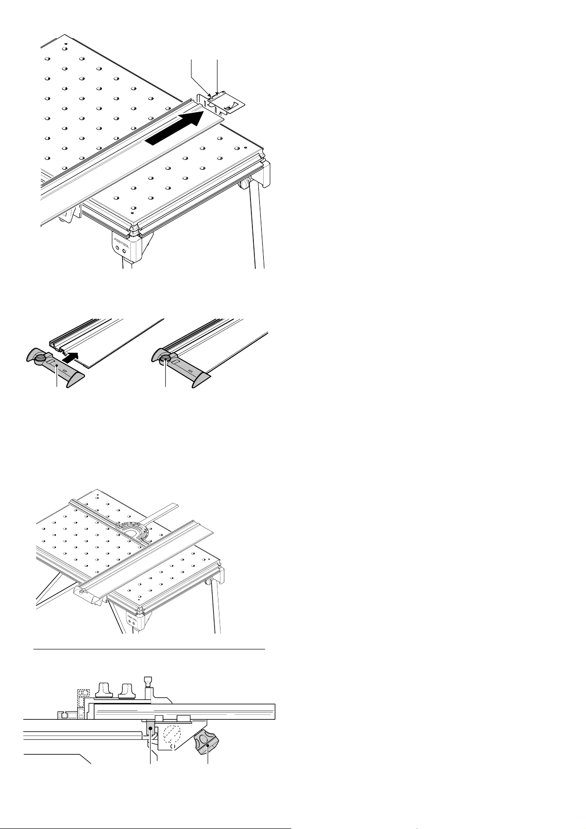
Step 4: Attaching the guide rail
5-25-1
To attach the guide rail, place on the key
[5-2] and make sure that the end of the
rail is resting on the support plate and the
key is located correctly in the groove.
Secure the guide rail in this position with
the two screws [5-1] and tighten using the
hexagon wrench.
Lower the guide rail onto the support unit
so that the groove in the underside of the
guide rail fi ts on to the pin [4-5] of the
support unit. The guide rail is properly attached when only a very slight lateral pressure is necessary for the pin to engage into
the guide rail.
The defl ector [6-1] is pushed onto the end
of the guide rail. Close the rotary knob
[6-2]. The defl ector prevents the extrac-
tion hose and the power cable from catching on the guide rail.
6
7
Step 5:
Attaching the pre-set
profi le setting rail
The rail can be attached at any point along
the clamping edge of the bench and is so
versatile, it can be used as a cross stop or
a longitudinal stop.
NOTE: Before attaching, make sure that
the V groove on the fence is not dirty.
Open the clamping jaws using the knob
[7-2]. Place the fence with guide rail [7-1]
onto the clamp rail from above. Secure the
clamp segment using the knob [7-2].
7-1
7-2
7
8
9-1
90°
9-2
9-3
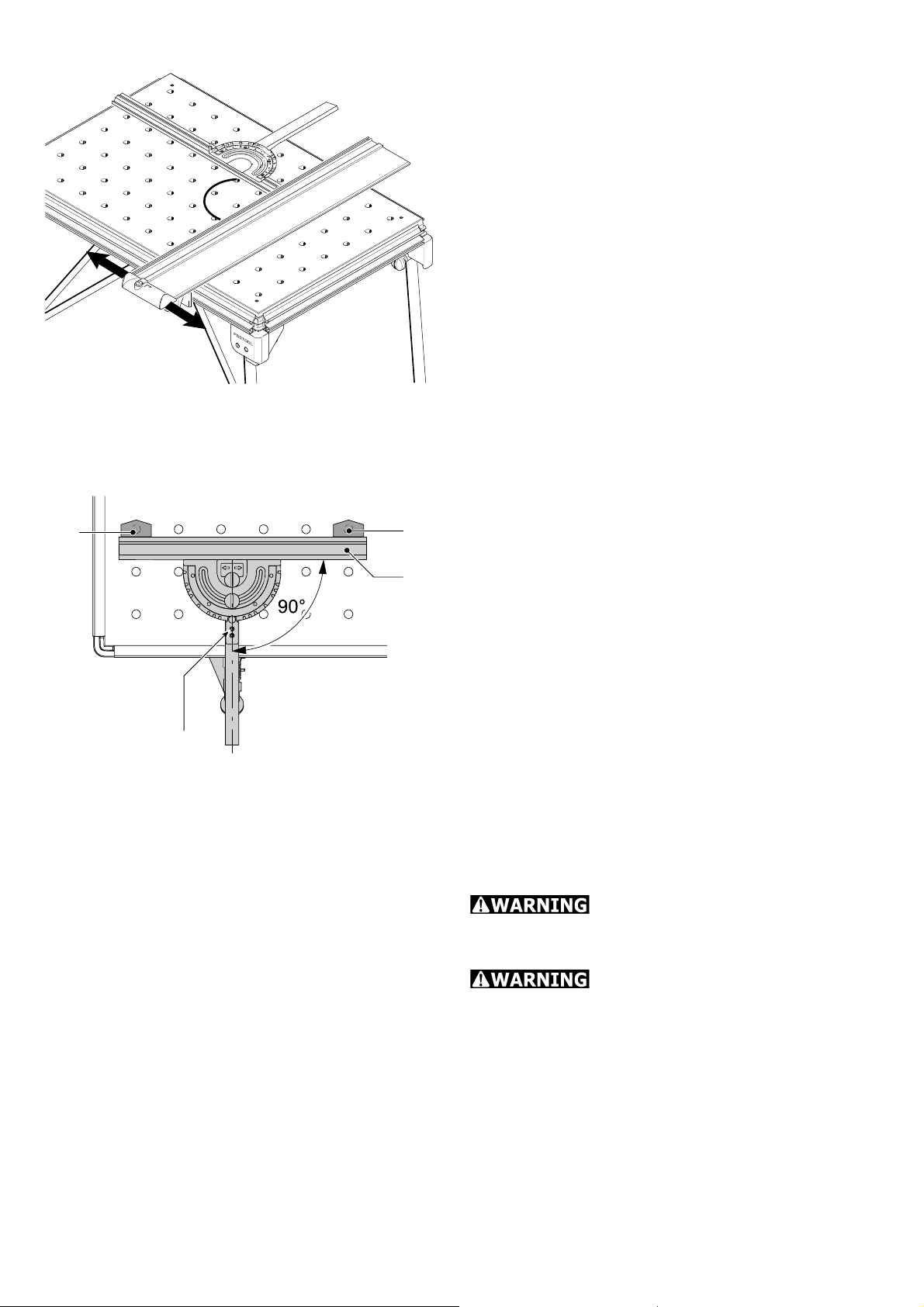
Step 6: Calibrating angle
Check the angle setting of the pre-set profi le setting rail before starting work. Align
the guide rail fi rst of all [Fig. 8].
Align the guide rail at right angles to the
pre-set profi le setting rail. If an angle of
90° is not possible, slide a support unit on
the guide rail until the angle is correct. Secure the guide rail.
NOTE: Slide the relevant stop [4-3] along
the table profi le to retain the setting per-
manently.
If required, the pre-set profi le setting rail
can also be aligned in relation to the perforated top provided the necessary clamps
(accessories) are available.
Insert the clamps [9-1] and [9-2] as shown
in Fig. [9] and move the stop ruler [9-3] to
a 90° position.
If the stop ruler does not rest evenly
against the clamps:
9
9-4
Loosen the screws [9-4] and the rotary
knob [7-2]. The retaining pin must be engaged in the 90° notch.
Set the angle at 90° in relation to the
clamps and tighten the screws.
Step 7: Adjusting the pre-set
profi le setting rail
Risk of injury! Always use
the fence in a fi xed position and do not use
to slide the workpiece along!
Risk of injury! Make sure
that all rotary knobs on the fence are tightened before starting work.
The fence can be adjusted in the following
ways:
8
10-1
10-2 10-3
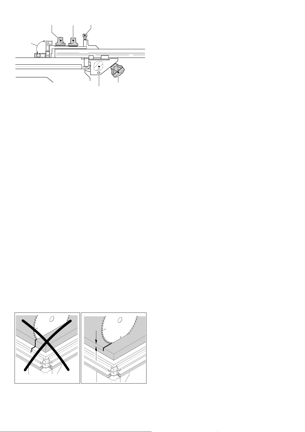
Adjustment parallel to the bench edge:
Loosen the rotary knob [10-4].
10-6
10
10-5
10-4
Adjustment at right angles to the
bench edge:
Loosen the rotary knob [10-4].
Adjusting the stop ruler [10-5]
lengthways
Loosen the rotary knob [10-1]. The stop
ruler can be moved to a lower position for
thin workpieces or a higher position for
thicker workpieces.
Angle adjustment using the scale
Loosen the rotary knob [10-2] and lift the
retaining pin [10-3]. The rotary retaining
pin engages in the most common angle
positions.
Step 8: Adjusting the guide rail
in relation to the workpiece
max. 5 mm
For sawing and routing applications, the
guide rail can be lowered via [1-2] and
[1-4] so that the rail rests evenly on the
workpiece. The workpiece and the rail are
retained securely.
A support piece of suitable thickness is
placed centrally under the guide rail between
the workpiece and the support unit [1-2] so
that the guide rail does not tilt when narrow
workpieces are machined.
Step 9: Adjusting the cutting
depth for sawing [Fig. 11]
Always make sure that the cutting depth
setting is correct in relation to the workpiece
thickness. We recommend setting a cutting
depth to a maximum of 5 mm more than
the workpiece thickness to protect the profi le frame from damage.
11
9
12
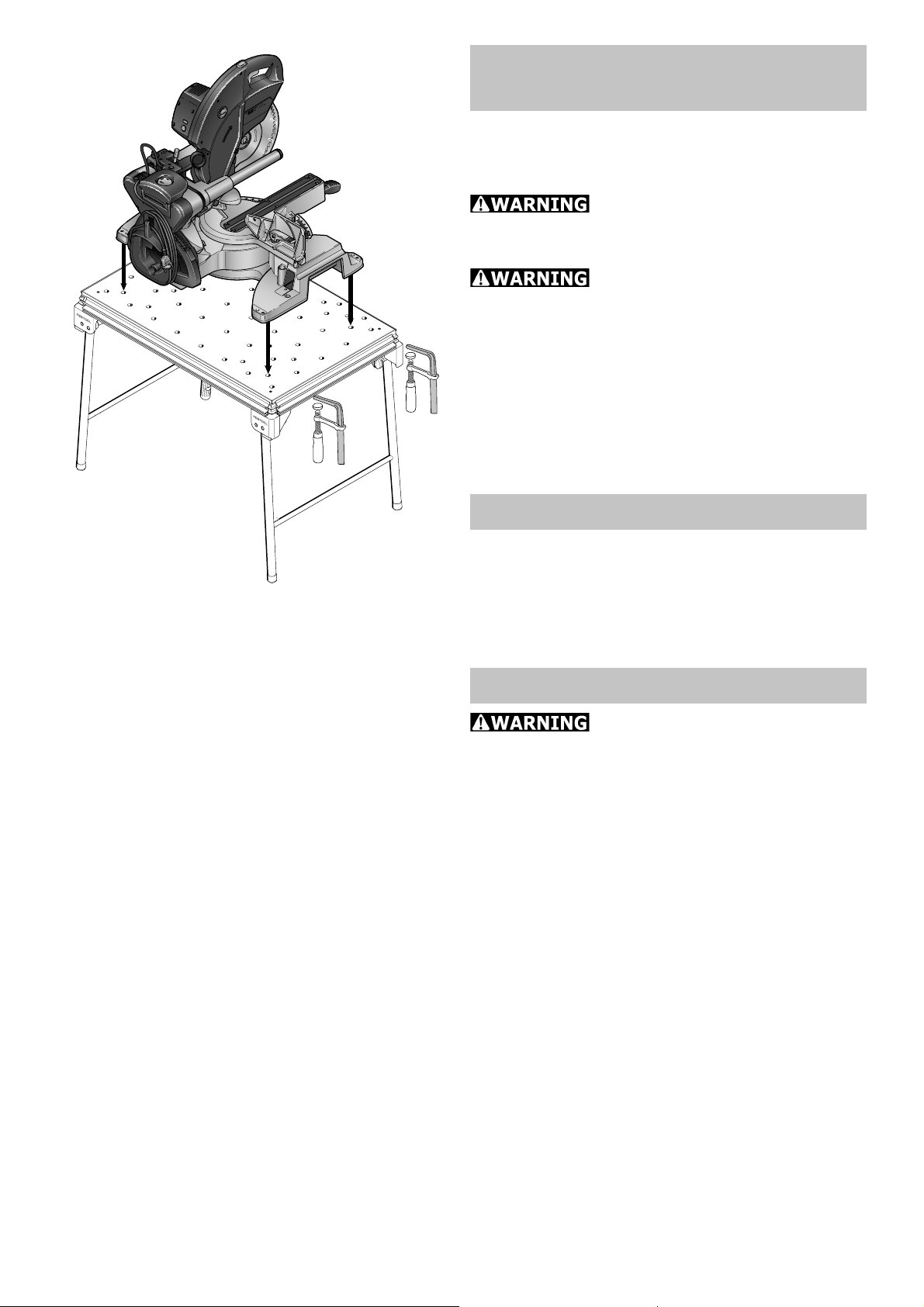
MFT/KAPEX:
Mounting the KAPEX
The perforated top on the MFT/KAPEX was
specially designed for mounting the KAPEX
KS 120.
Risk of injury! Before start-
ing work, make sure that the machine is
secured properly
Risk of injury! Respect the
maximum workpiece dimensions.
Mount the machine on the MFT/KAPEX as
shown in Fig.[12].
Secure the machine to the MFT using
clamps.
Maintenance
Turning the perforated top
When worn on one side, the perforated top
can be turned over. Loosen the four screws
in the corners underneath the bench.
Accessories, tools
For safety reasons, only
use original Festool accessories and
tools!
The accessory and tool order number can
be found in the Festool catalogue or on the
Internet under www.festool-usa.com.
10
 Loading...