

Page 1

GuiLin FeiYu Electronic Technology Co., Ltd
FY-40A Flight Stabilization System
Installation & Operation Manual
Dear Customers,
Thank for choosing FY-40A as your inertial stabilization solution. Please read this manual
carefully before using the system to ensure proper use and operation. If you need any technical
support kindly contact us directly: service@feiyu-tech.com .
1、Operating Principle And Function
FY-40A has an integrated three-axis gyro and three-axis accelerometer which controls the
aircraft movement in three-dimensional space. By using your remote control, the unit can be turned
on or off for the following functions:
●Mode 1: FY-40A Deactivated Mode In this mode, the FY-40A stabilization function is turned off.
The aircraft is completely under the control of the pilot.
●Mode 2: Auto Stabilization Mode In this mode, the FY-40A will automatically command the
aircraft control surfaces to maintain level flight at all times.
●Mode 3: 3D Control Mode In this mode, the balancer utilizes its 3-axis gyroscope to sense roll
velocity and flight attitude. If no input is given by the pilot (sticks in the middle position) the FY-40A
will lock the current aircraft attitude. This prevents rolling of the aircraft at the axial plane and
maintains its current posture. Therefore the aircraft can be easily maneuvered to complete a variety
of 3D flight with added stability and smoothness.
Guilin Feiyu Electronic Technology Co., Ltd http://www.feiyudz.cn service@feiyu-tech.com
Page 1
Page 2

GuiLin FeiYu Electronic Technology Co., Ltd
2、Technical Specification And Working Requirement
●Input Voltage : 4.0 ~ 6.0 Volt;
●Current Draw : 50mA (5V);
●Size : 45mm x 30mm x 9 mm;
●Weight (Excluding Wires) : 17g;
●Temperature Range : -25 ° C ~ +70 ° C;
●Maximum Rate Of Rotation : ≤ 2000 °/s;
3、Aircraft Suitability
●Traditional layout fixed-wing aircraft
●Flying wings with rudder
●Flying wings with no rudder
●Airplanes with no ailerons (rudder and elevator only)
●V-tail airplanes with aileron and with no ailerons
4、Standard Configuration
●FY-40A control module * 1
●RC receiver connecting wires * 1
●Velcro double sided tape * 2
●Instruction manual * 1
●Gyro sensitivity adjustment screwdriver* 1
Guilin Feiyu Electronic Technology Co., Ltd http://www.feiyudz.cn service@feiyu-tech.com
Page 2
Page 3
GuiLin FeiYu Electronic Technology Co., Ltd
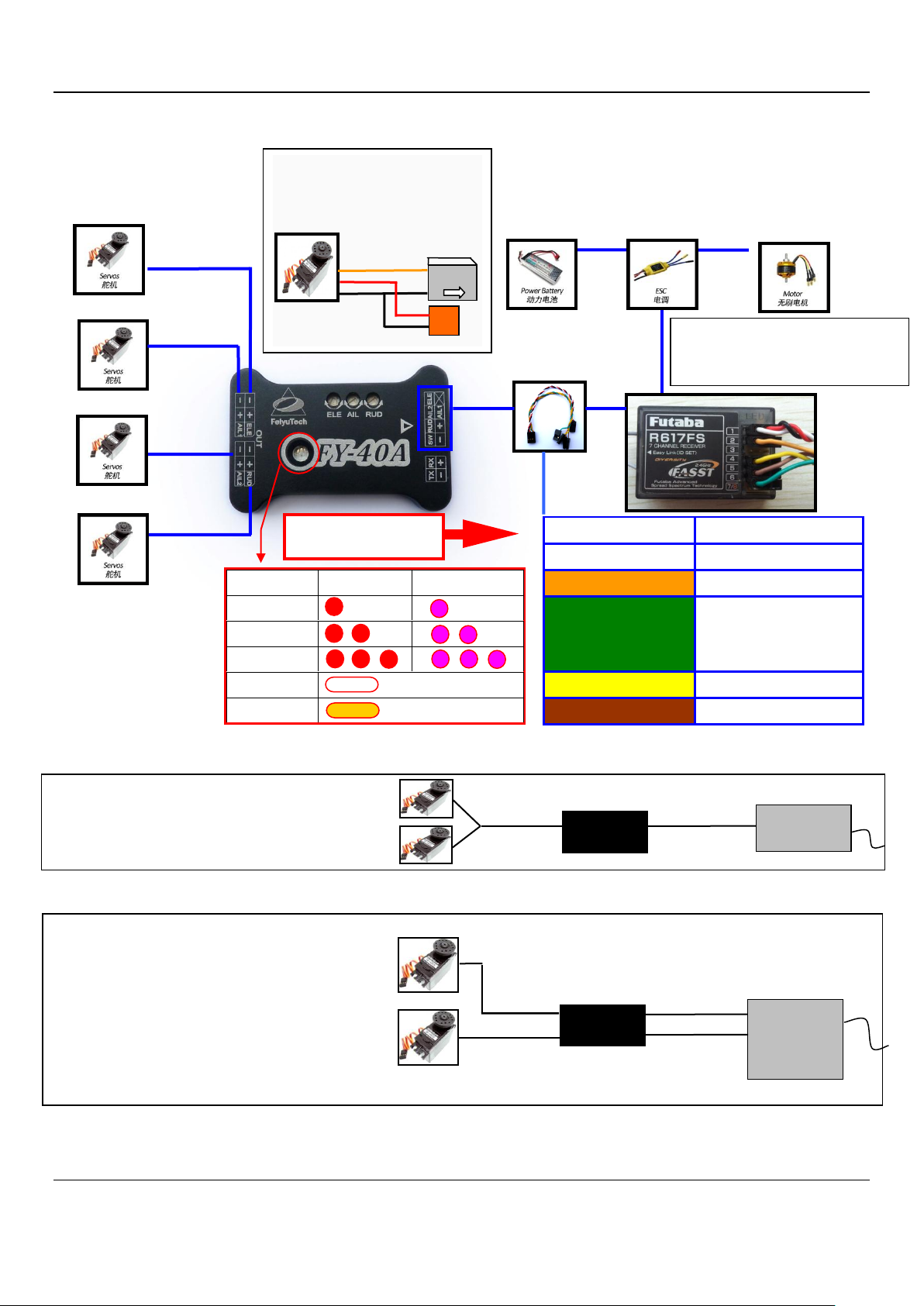
Attention:When ailerons also were used as the flaps,
Please respectively connect two aileron servos to
AIL1 and AIL2 ports. Make CH6 and AIL channels
linked, also set up a switch to control flap function.
May be only part of the remote control to
support this function. Detailed instructions please
refer to the manual of the remote control.
AIL
RC receiver
AIL1 OUT
AIL1
FY-40A
AIL2
CH6
AIL2 OUT
Color
Function
White (red & black)
Aileron 1 input
Orange
Elevator input
Green
Aileron 2 input (when
your aircraft is using
flap)
Yellow
Rudder input
Brown
Switch channel input
ELE
CH5 is used for switch channel. When the
aileron contain flap function and you want
to use it,please set CH6 as second
aileron input.
THR
AIL1
AIL2
RUD
State
LED
Gyro need reset
RC
stabilized
3D
Gyro rest
Mixed
Orient the arrow towards
the front of the aircraft
When using large torque servo,
We suggest you power on it
alone, you can refer to below :
5V
FY-40A
+5V
GND
Attention: Normally, please do not use AIL2 port,
just use a Y cable to connect two aileron servos
to AIL1 port.
AIL1
Not connect AIL2
AIL1 OUT
Y cable
RC receiver
FY-40A
5、Connection Diagram
Guilin Feiyu Electronic Technology Co., Ltd http://www.feiyudz.cn service@feiyu-tech.com
Page 3
Page 4

GuiLin FeiYu Electronic Technology Co., Ltd
RC
ABM
3D
Interface
Traditional
Flying wing
(Aileron &Elevator
mixed control servo)
V tail
(Elevator &Rudder
mixed control)
Airplanes with
no ailerons
ELE
Elevator servo
Mixed control servo 1
Mixed control servo 1
Elevator servo
AIL1
Aileron servo 1
Mixed control servo 2
Aileron servo 1
Rudder servo
RUD
Rudder servo
Rudder servo
Mixed control servo 2
AIL2
Aileron servo 2
( when using flap
function )
Aileron servo 2 ( when
using flap function )
Receiver signal output
900~1200US
1200~1800US
1800~2100US
Work Mode
RC
ABM
3D
LED
6、Servo Interface Connection Instructions
7、Switch Setting For FY-40A Flight Modes
FY-40A requires a minimum of 5-channel RC receiver.4 Receiver
channels are used for aileron (channel 1), elevator (channel 2) ,
throttle (channel 3) and rudder (channel 4) signal output. 1 free
Receiver channels are required to control the FY-40A Flight Modes (a
3-position switch or dial knob, ”SW”).If you do not connect
SW,FY-40A will work on “ABM” mode.
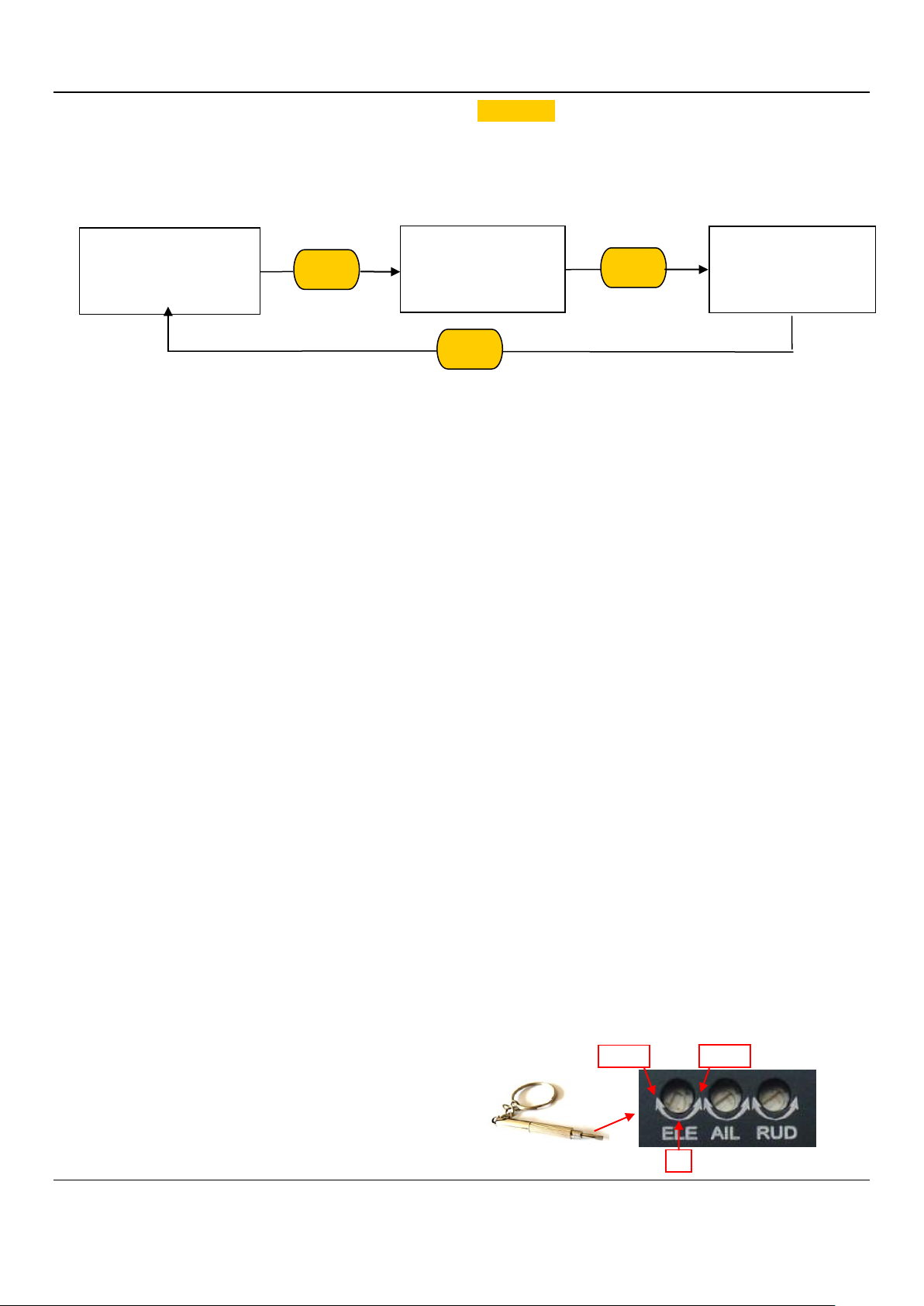
8、Setting The Mixing Control Mode
First, you should set the remote control is the fixed-wing aircraft conventional layout mode,
do not set any mixing control. FY-40A can be achieved " Aileron &Elevator mix control "and "
Elevator &Rudde rmix control ", you can through SW to set it.On SW, within10 seconds from the
“Auto Stabilization mode”→“3D mode”→“Auto Stabilization mode”repeatedly fast switch six
Guilin Feiyu Electronic Technology Co., Ltd http://www.feiyudz.cn service@feiyu-tech.com
Page 4
Page 5
GuiLin FeiYu Electronic Technology Co., Ltd
0
+MAX
-MAX
Conventional layout
(No mixed control)
Aileron &Elevator
mixed control
Elevator &Rudder
mixed control
times, You will see the light flashes yellow. After YellowLED turns off, the mixing control mode
Setting is completed.
The mixed control setting will cycle changes like picture below shows:
9、Gyroscope Reset
FY-40A has motion detection function, if it's moving, work mode indicator red LED will
become purple. But if the indicator LED still purple even when the FY-40A remains stationary,that
means you need to do the Gyro reset.
Initialization / Reset Process:
(1) Power on FY-40A and keep stationary.
(2) Switch to Auto stabilization mode.
(3) On SW, switch Auto stabilization mode to Deactivated mode 6 times, time interval has
to be less than 3 seconds as follows:
Auto stabilization mode→ Deactivated mode →Auto stabilization mode →Deactivated mode
→Auto stabilization mode→ Deactivated mode →Auto stabilization mode →Deactivated mode
→Auto stabilization mode →Deactivated mode→Auto stabilization mode →Deactivated mode.
(4) FY-40A indicator will turn white about one second.
(5) After white LED turns off, the re-setting / initialization is completed.
10、Adjustment Dials For ELE, AIL And RUD
(1) There are 3 adjustment dials on the
FY-40A. Each dial controls both gyro gain and
servo direction during auto stabilization.
Guilin Feiyu Electronic Technology Co., Ltd http://www.feiyudz.cn service@feiyu-tech.com
Page 5
Page 6

GuiLin FeiYu Electronic Technology Co., Ltd
Servo direction
change during
auto stabilization
Servo direction
change during
auto stabilization
Max Gyro Gain
Max Gyro Gain
6 O’clock
Min Gyro Gain
Left aileron
automatically
moves upward
Roll right
Right aileron automatically
moves downward
Right aileron
automatically
moves upward
Left aileron automatically
moves downward
Aileron Movement In Auto Stabilization Mode
Roll left
(2) Gyro Gain: The further away from Centre (6 O’clock) the higher the Gyro gain
(sensitivity). Too low gain result is poor auto stabilization, too high gain will cause oscillations of
the aircraft. You need to adjust the gain setting based on the requirement of your aircraft.
(3) Servo Direction: The dials also control the direction of your servo movement. Turning it
clockwise or counter clockwise from 6 O’clock will change the direction of your servos during
tilting, roll and yaw movement.
Switch to the "Auto Balance Mode" mode, check the auto control movement direction as
explained below:
11、Aileron Servo Auto Movement Check
RIGHT Roll the plane & the right aileron should automatically move downwards, while the left
aileron moves up.
LEFT Roll the plane & the left aileron should automatically move downwards, while the right
aileron should move up.
If the servo movement is incorrect, you need to reverse the automated servo movement via
the AIL dial.
Guilin Feiyu Electronic Technology Co., Ltd http://www.feiyudz.cn service@feiyu-tech.com
Page 6
Page 7

GuiLin FeiYu Electronic Technology Co., Ltd
Elevator moves down
Elevator
moves up
Nose Up
Nose Down
Elevator Movement In Auto Stabilization Mode
Turn left
Rudder moves to the right
Turn right
Rudder moves to the left
12、Elevator Servo Auto Movement Check
UPWARD Incline the plane nose & the elevator should automatically move downwards.
DOWNWARD incline the nose & elevator should automatically move upwards.
Servo movement is incorrect, reverse it via the ELE dial.
13、Rudder Servo Auto Movement Check
CLOCKWISE rotate your plane & the rudder should move to the Left.
COUNTER CLOCKWISE rotation & the rudder should move to the Right
Servo movement is incorrect, reverse it via the RUD dial.
14、Other Considerations
Damping Installation: FY-40A is vibration-sensitive. To optimize its stabilization capability,
vibrations reaching the unit must be kept at a minimum. Good damping installation is the basis of
Guilin Feiyu Electronic Technology Co., Ltd http://www.feiyudz.cn service@feiyu-tech.com
Page 7
Page 8
GuiLin FeiYu Electronic Technology Co., Ltd
FY-40A
Mounting Surface
FY-40Acan do normal work, also can decide whether FY-40A to maximize play flight performance
or not, and make sure you have a great flight,otherwise may cause serious flight accidents. You
can use your own DIY shock absorbing devices to do the shock absorbing, but we recommend
using suspending damping installation.
3D Mode:If no input is given by the pilot (all sticks in the middle position), 3D mode will lock the
current aircraft attitude. Therefore the aircraft can be easily maneuvered to complete a variety of 3D
flight with added stability & smoothness.
Attention: Please make sure the RC stick is released when you switch into 3D Mode. The
FY-40A can record current RC stick position and lock the flight attitude when your RC stick
released.
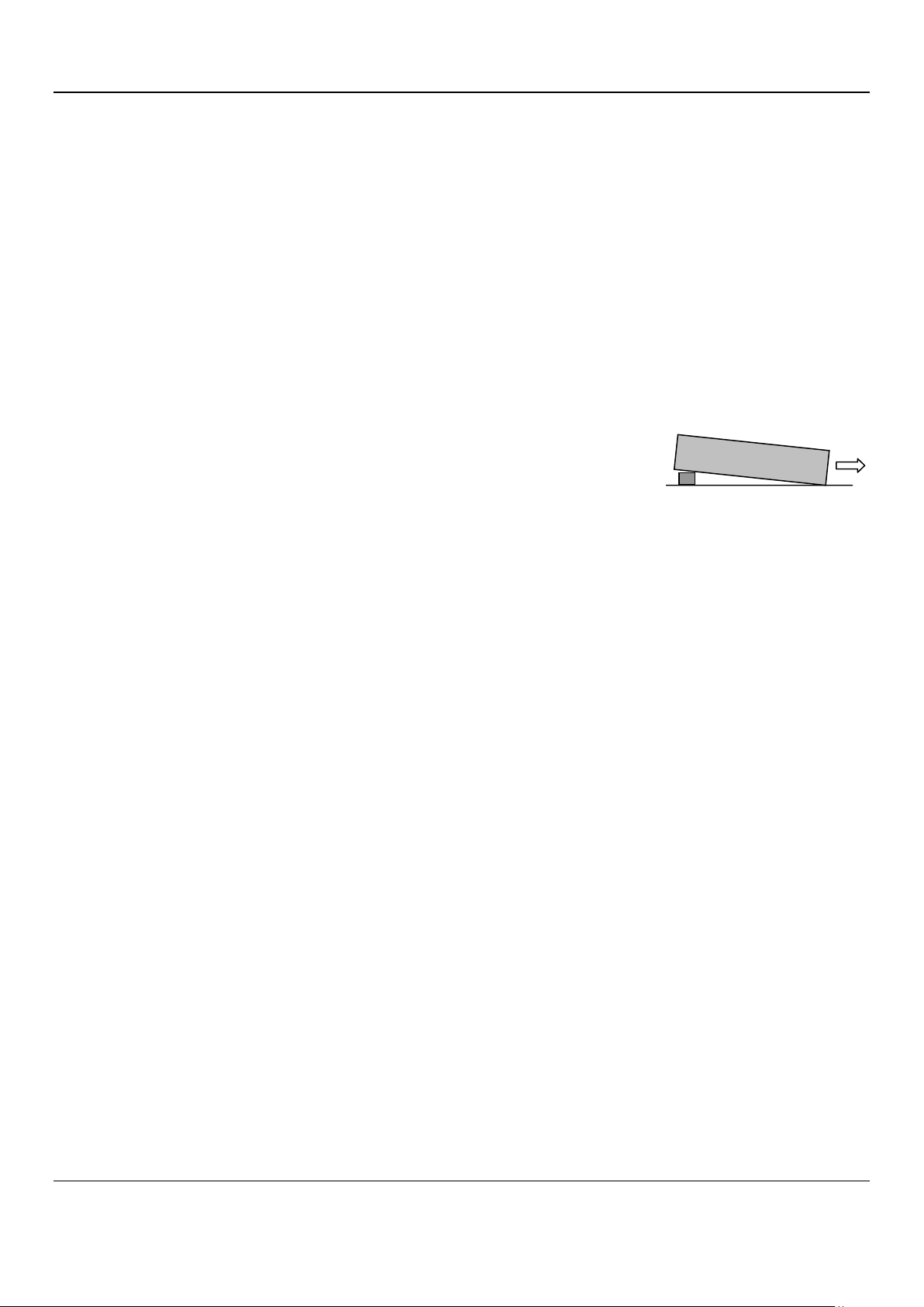
In Auto Stabilized Mode:At Activated Mode can be straight and
level flight, stick sw1 to Stabilized Mode, if the airplane is not level
flight , for example ,it drive to dowm, you can adjust angle of installtion
prevent plane down, this time can change the FY-40A pitch, example, the rear pad FY-40A high.
Gyro sensitivity adjustment:Please do not use very high sensitivity during your first flight in
order to avoid control shock which cause by FY-40A give too much auto control movement to
your aircraft.. Please take off and switch in to Auto Stabilization mode. Manually to change the
plane roll and pitch, etc., to observe the plane automatic balance situation. If recover to balance
is too quick, don't feel flexible operation you can reduce corresponding channel control gain; If
the pitch, roll and orientation rapid shaking, or flight speed increases appear sloshing, you need
reduce corresponding control channel gain; If recover to balance is too slow, the poor control
ability is require you to increase control gain.
Safety Measures:Balancing instrument is designed to keep flying balance. It can not control the ai
rcraft or prevent stalling. You must control the flight direction of the aircraft, and make sure youself
know that where the airplanes fly. The balancing instrument only use for entertainment . Please d
on’t install to the aerial photography aircraft that likely flew over the crowd. Any electronic product
and equipment on the Machine can not be completely reliable, Before you use FY-40A Airplane ba
lancing instrument, you should make a assess for the product, Our company don’t liable for any da
mage caused by using the product and the consequences. Our company do not responsible for
any losses and effects of using the product.
—— END ——
Note: We reserve the right to change this manual at any time! And the newest edition will be shown
on our website www.feiyudz.cn.
Guilin Feiyu Electronic Technology Co., Ltd http://www.feiyudz.cn service@feiyu-tech.com
Page 8
 Loading...