

Page 1
GuiLin FeiYu Electronic Technology Co., Ltd http://www.feiyudz.cn E-mail: service@feiyu-tech.com
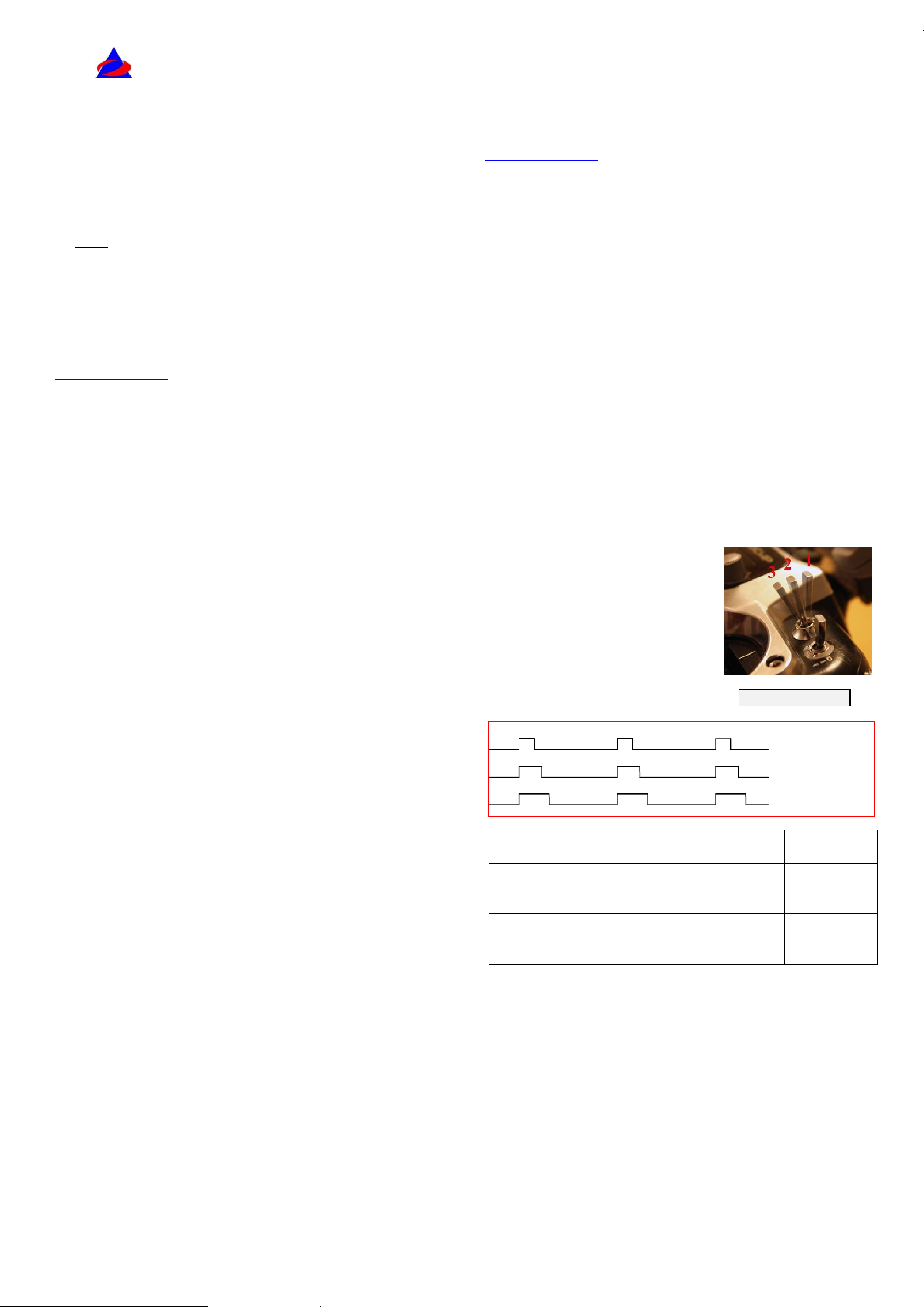
Flight
Modes
MODE 3
MODE 2
MODE 1
Receiver
signal
output
900-1200uS
1200-1800
uS
1800-2100
uS
FY30A
Function
Auto
Stabilization
mode
3D Mode
Manual
Mode
FeiyuTech
Switch setting example
RC Receiver Signal output:
900-1200us Auto Stabilization Mode
1200-1800us 3D Mode
1800-2100us Manual Mode
FY-30A Flight Stabilization System
installation & operation manual
Dear Pilot,
Thank for choosing FY30A as your inertial stabilization solution.
Please read this manual carefully before using the system to ensure
proper use and operation.
Note:
The installation and use of this device require some skill and
knowledge in flying remote controlled fixed wing aircraft.
If you are a complete beginner and have never flown one before, we
do not recommend you install this device on your own.
Please find assistance from an experience RC Pilot who may provide
you with the basic knowledge required to use this device
successfully.
If you are already an experienced flyer, you will find the FY30A
installation to be easy and logical. Just follow this manual and you
won’t go wrong.
If you need any technical support kindly contact us directly:
service@feiyu-tech.com .
INTRODUCTION
FY-30A is an inertial attitude measurement instrument used for
automated stabilization of fixed wing model aircrafts and two axis
camera gimbals.
FY30A has an integrated three-axis gyro and three-axis
accelerometer which controls the aircraft movement in
three-dimensional space. By using your remote control, the unit can be
turned on or off for the following functions:
Level flight – When stabilization is activated, the FY-30A
will automatically control the aircraft for smooth easy flying. For
beginners in RC aircraft flying, this is advantages as it makes flight
easier and increases the student pilot self-confidence. The system can
be activated throughout the entire flight duration, from take off to
landing.
Emergency Recovery - If you lose orientation or feel the
plane out of control, then release all control sticks, maintain throttle
and switch on the FY30A. The unit will automatically send the correct
signals to balance of the aircraft and regain level flight.
Aerobatics – for the experienced fixed wing 3D pilot, the
FY-30A can help you achieve a more accurate flight path, especially in
windy conditions. FY-30A makes 3D maneuvers such as inverted flight,
knife-edge, crane etc easier and simpler to achieve and maintain. A
great way to practice and improve your 3D flying.
First Person View - for long-distance RC flight via video
transmitter, the FY30A will maintain the balance of your aircraft. You
only need to control the heading of your aircraft and enjoy the view.
Firmware upgrade – The FY30A firmware is upgradable
by connecting to your computer via a USB TTL cable. As Feiyu Tech
continuously improves the FY30A system, firmware upgrades will be
released periodically.
Aileron, Elevator and Rudder;
Flying wings with rudder and with no rudder;
Airplanes with no ailerons (rudder and elevator only)
V-tail airplanes with aileron and with no ailerons
Any other configuration inquiries, please email us:
service@feiyu-tech.com .
RC Radio suitability:
The FY-30A has been tested to work well with the following RC system:
Robbe-Futaba PPM / PCM 1024 / PCM G3 mode, 2.4G systems;
Graupner / JR PPM 8, PPM 12, SPCM mode;
MPX PPM8, PPM 12 with UNI mode;
Any other system with a neutral position of 1.5 ms (standard in most RC
Radios).
FY-30A Operating Mode
The FY-30A can be operated in three flight modes:
Mode 1: FY-30A Deactivated Mode. In this mode, the FY-30A
stabilization function is turned off. The aircraft is completely under the
control of the pilot.
Mode 2: 3D Control Mode. In this mode, the balancer utilizes its
3-axis gyroscope to sense roll velocity and flight attitude. If no input is
given by the pilot (sticks in the middle position) the FY30A will lock the
current aircraft attitude. This prevents rolling of the aircraft at the axial
plane and maintains its current posture. Therefore the aircraft can be
easily maneuvered to complete a variety of 3D flight with added
stability and smoothness.
Mode 3: Auto Stabilization mode. In this mode, the FY-30A will
automatically command the aircraft control surfaces to maintain level
flight at all times.
Switch Setting for FY-30A Flight
Modes
a) To activate the different flight
modes, use a free Receiver channel (e.g.
Channel 5) to output the appropriate signal
to the FY30A.
b) Use a 3 way-switch from your
RC radio as in the example at right:
How it works
The core of the FY-30A is the integrated 3-axis gyro and 3-axis
accelerometer which is the basis for its inertial sensing. The FY30A is
an inertial navigation platform with a strap down attitude algorithm
designed for fixed wing aircraft stabilization.
When the FY-30A is in auto-balance mode, it detects the aircraft
attitude and horizontal positioning and issues commands to servos that
adjust the aircraft control surfaces (Aileron, Elevator and Rudder) so
that the aircraft remains level at all times. Due to this autonomous
action to maintain smooth level flight, the FY-30A makes flying very
easy.
When the FY-30A is operating in 3D mode and the aircraft is in an
acrobatics flight, the FY30A will use the 3-axis gyroscopes to calculate
roll velocity and overall flight attitude. With this data, the system
outputs control corrections to maintain smooth aircraft attitude even
when doing aerobatics flight.
Since the FY30A is self contained, it can be used in all weather
conditions, indoors or outdoors. Just power up and take off.
Aircraft Suitability
The FY30A can be used in the following fixed wing models:
Traditional layout fixed-wing aircraft with
c) You may use a 2-position switch, setting the maximum and
minimum End Points (EPA) to activate or deactivate flight stabilization
(omitting 3D-Mode).
d) If you do not connect the Switch channel to your RC
Receiver or the FY-30A does not detect any incoming signal through
this input channel, it will automatically engage Mode 3- Auto
Stabilization Mode. However, we do not recommend flying the unit with
no signal input to the Switch Channel.
e) Please note that even though there is a Throttle Input and
Throttle Output from the FY30A, the system does not overlay any
servos control quantity. As to say, the FY-30A is just used for signals
connecting. As a pilot, you must always ensure your aircraft has enough
cruising speed to prevent stall.
f) Warning: The Auto Stabilization Mode will provide a
smoother leveled landing for your aircraft. However, note that the
turning radius is larger when in this mode. Please ensure your landing
area has adequate clearance for this larger radius.
GuiLin FeiYu Electronic Technology Co., Ltd page 1
Page 2
GuiLin FeiYu Electronic Technology Co., Ltd http://www.feiyudz.cn E-mail: service@feiyu-tech.com
Switch
number 1 2 3
4
ON
For Factory
use only
Flight Mode
Selection
Flight Mode
Selection
Adjust flight
patterns
OFF
Always OFF
position
Flight Mode
Selection
Flight Mode
Selection
Normal mode
Blue LED
Continuous
flashing
On Solid
Single flash
Flight Mode Status
manual mode
Auto Stabilization
3D mode
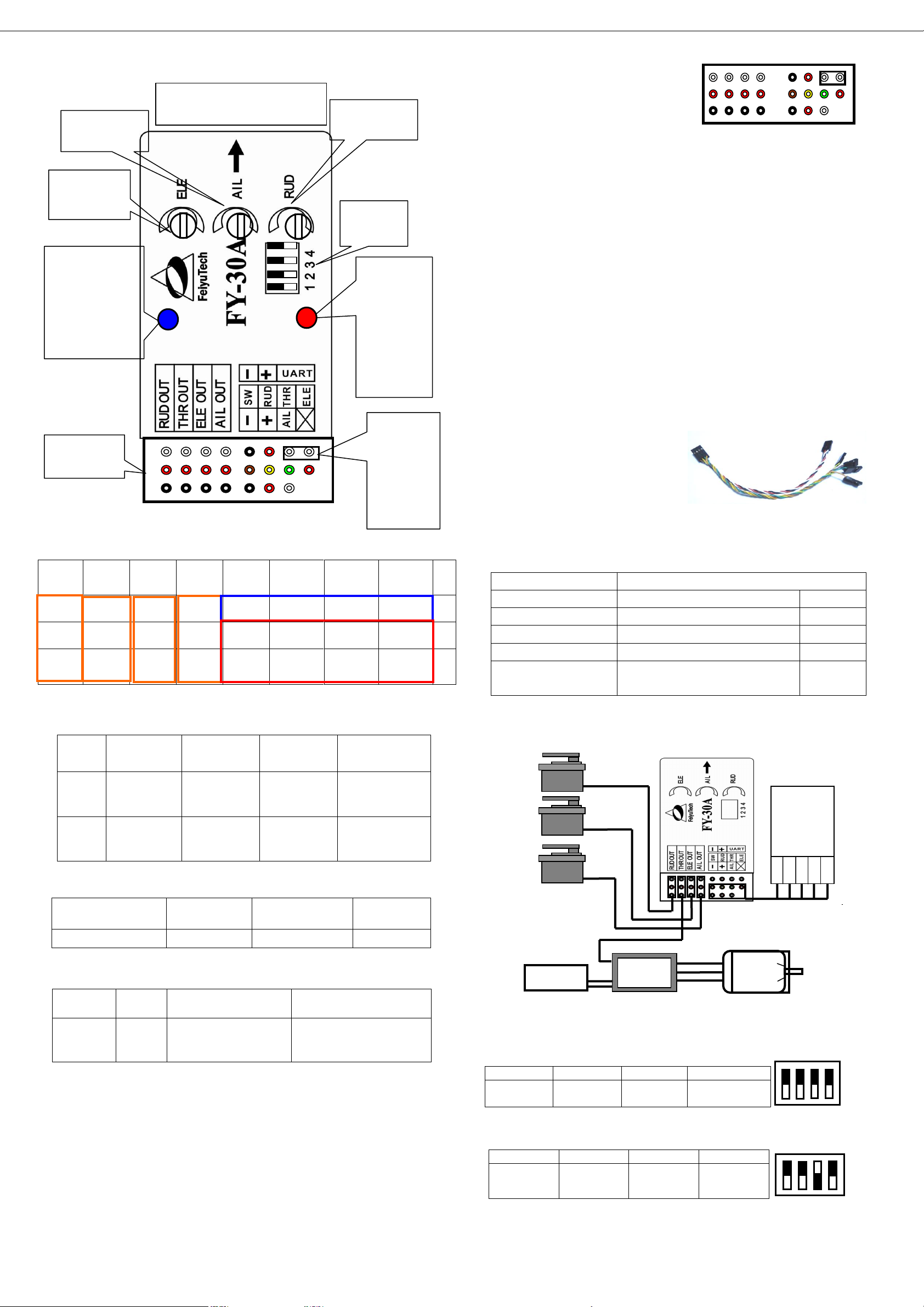
AIL OUT
ELE OUT
THR OUT
RUD OUT
Differential
Servo 1
Differential
Servo 2
ESC
Rudder
servo
8 7 6 5 4 3 2
1
N
O.
Rudder
out
Throttle
out
Elevator
out
Aileron
out
Ground
Power
TX
RX
A
Power
Power
Power
Power
CH5
(Switch)
CH 4
(Rudder)
CH 3
(Throttle)
CH 2
(Elevator)
B
Ground
Ground
Ground
Ground
Ground
Power
CH 1
(Aileron)
NULL
C
Red LED
OFF
Aircraft is stationary
but Red LED Flashes
ON Solid
Status
Indicator
Normal
Need to initialize
the gyro
High Vibration Detected.
Does not meet system
requirement.
Wire color
Receiver channel
White (red and black)
Aileron
Channel 1
Orange
Elevator
Channel 2
Green
Throttle
Channel 3
Yellow
Rudder
Channel 4
Brown
Controlled via 3-Way or 2-Way
switch
Channel 5
AIL OUT
ELE OUT
THR OUT
RUD OUT
Aileron
servo
Elevator
servo
ESC
Rudder servo
ON
OFF
4
3
2
1
B
A
8
C
7
6 5 4 3 2 1
1
2 3 4
OFF
ON
POINT ARROW FORWARD
(TOWARDS FLIGHT DIRECTION)
Aileron
sensitivity knob
Elevator
sensitivity
knob
Rudder
sensitivity knob
Function
DIP switch
Red LED:
Solid ON
indicates
vibration is
too severe.
Flashes when
stationary:
indicate need
for gyro
initialization.
Blue LED: Flight
mode indicator.
Always On: Auto
Stabilization
Single flashing: 3D
mode.
Continuous flash:
manual mode.
Interface pin
panel
Jumper
installed
during gyro
initialization.
Do not insert
jumper
during
normal use.
B
A
8
C
7
6 5 4 3 2
1
Battery
ESC
(CH 3)
Electric
motor
RC
Receiver
ELE
THR
RUD
AIL
CH5
RUD OUT
ELE OUT
AIL OUT
FY-30A interface
Pin interface to sort the list
You will notice the red light blink at
two different rates (or turns off). Gyro
re-setting is complete. Disconnect
power, unplug the jumper and keep it
in a safe place for future use).
NOTE:
Carry out this re-setting procedure only if the 3 conditions (above)
occur. It is not recommended to regularly reset the gyro. It is not
necessary.
The stabilizer unit does not need to be in a horizontal position
during initialization. However, you must ensure there is no vibration
during this process. If you suspect shaking had occurred, just restart the
resetting process.
FY30A power supply
FY30A working voltage = 5 to 6V.
The FY30A require stable power input. Therefore, we highly
recommend using an External BEC power supply with minimum 3A
output. The higher the better.
Be sure to remove the Red wire from your ESC plug if using an
external BEC.
BEC should be plugged into your RC Receiver. Power is sent to
the FY-30A via Channel 1 input.
FY-30A colour coded cable to
RC Receiver:
RC Receiver Requirement
a) FY-30A require at least a 5
channel receiver
b) Plug in the cable into the FY30A and connect to the RC Receiver
following these colour codes:
DIP Switch Function:
Blue LED
Red LED
c) Note Channel 5 will output the signal to control the 3 flight
modes of the FY-30A. Therefore assign a 3-way or 2-way switch to this
channel.
DIP Switch Setting
DIP Switch Setting
Gyroscope initialization (re-setting):
Out of the box, the FY-30A has been fully initialized. However, if the
following conditions occur, resetting the gyro is recommended:
1. The device has not been used for a long time.
2. There is a change in environmental temperature of over 30 degrees.
3. When the red LED light flashes even when the aircraft is stationary.
Initialization / Reset Procedure
Install the jumper as shown in this picture:
Power-ON the FY-30A and keep it stationary for at least 20 seconds.
a) FY3OA connection for traditional aircraft layout:
b) FY30A connection for flying wing aircraft (with or without Rudder):
GuiLin FeiYu Electronic Technology Co., Ltd page 2
Page 3

GuiLin FeiYu Electronic Technology Co., Ltd http://www.feiyudz.cn E-mail: service@feiyu-tech.com
AIL OUT
ELE OUT
THR OUT
RUD OUT
Aileron servo
Differential
Servo 1
ESC
Differential
Servo 2
AIL OUT
ELE OUT
THR OUT
RUD OUT
Differential
Servo 1
Differential
Servo 2
ESC
NULL
AIL OUT
ELE OUT
THR OUT
RUD OUT
Rudder
servo
Elevator servo
ESC
Null
AIL OUT
ELE OUT
THR OUT
RUD OUT
Roll Servo
Tilt Servo
NULL
Pan Servo
2
4
3
1
ON
OFF
2
ON
1
3
4
OFF
1
2
3
4
OFF
ON
ON
OF
1
2 3 4
Plane roll remains level when in Auto Stabilization Mode
Plane will roll to
the right when in
Stabilized Mode
Plane will roll to
the left when in
Stabilized Mode
FY-30A
Plane nose will pitch down when
in Auto Stabilization Mode.
Plane nose pitches up when
in Auto Stabilization Mode.
Plane pitch
remains level
when in Auto
Stabilization
Mode
FY-30A
Max Gyro Gain
Max Gyro Gain
12 O’clock
Min Gyro Gain
Servo direction
change during
auto stabilization
Servo direction
change during
auto stabilization
The 3 dials control both gain and
servo direction.
The gyro gain is lowest when the
knob in the middle. i.e. The further
away from center, the higher the
gyro gain.
Turning the knob left or right
off-center will change servo direction
for stabilization.
+100 Max
-100 Max
0 Min
c) FY30A connection for V tail aircraft with Aileron:
d) FY30A connection for V tail aircraft without ailerons:
e) FY30A connection for traditional layout aircraft with no Aileron:
f)Camera Gimbal Stabilization;
* Note: The camera gimbal Roll, Tilt and Pan servos will counter any
linear movement of the camera mount. You can move the camera at any
angle and upon releasing the stick, the FY30A will maintain
stabilization at that angle.
FY-30A and Vibration Control
a) FY-30A is vibration-sensitive. To optimize its stabilization
capability, vibrations reaching the unit must be kept at a minimum.
b) When installing this flight stabilizer, we highly recommend
that you install it with the supplied vibration absorbing pads (dampers).
c) The algorithm in the FY-30A compensates for normal levels
of flight vibration. However, if the vibration
experienced by the unit exceeds the
acceptable level, it will not work normally
or may even stop working altogether.
d) To keep vibration at a minimum,
install the FY-30A away from the engine or
any other vibration sources.
e) The included shock-absorbing
pads will meet the damping requirements
for electric powered aircrafts and most gas / nitro planes.
How to check installation requirements to meet the shock
Even with the shock absorbing mount, your aircraft installation may not
meet the damping requirements of the FSS. To confirm correct vibration
damping, please follow this procedure:
A. After connecting all wires between the Receiver, FY-30A and
Servos, install the unit as recommended (ensure correct orientation).
B. Run the plane engine or motor at different throttle levels. DO
NOT TAKE OFF.
C. Move the throttle level to different positions and maintain it
for 20 seconds at each position.
D. At each throttle position, observe the state of the red LED
light. If it stays OFF, that means your vibration level is acceptable.
E. If instead the red LED lights up brightly and stays ON solid,
then the vibration dampening is not enough. You will need reduce the
level of vibration on your aircraft, add additional dampening support or
change the installation location.
F. Vibration Security: An updated feature of the FY-30A is
emergency stabilization in case of sudden high vibration during flight.
In such a situation, the FY-30A will automatically activate the highest
level of stabilization and therefore withstand vibration better. This
feature should allow you to safely return the plane for an emergency
landing.
Fy-30a Installation: Orientation, Position & Level
i. The FY-30A has an arrow printed on the top of it. Orient the
arrow towards the front of the craft (i.e. direction of flight).
ii. When installing, please keep the FY-30A horizontal and as close
as possible to the "Centre of gravity" (C o G) of the aircraft.
iii. The benchmark for the FY-30A is its horizontal position.
Therefore, physically adjust the FY-30A into horizontal position when
the plane is in level flight:
GuiLin FeiYu Electronic Technology Co., Ltd page 3
iv. If there is deviation between the FY-30A horizontal position and
the plane’s level flight, it may cause the neutral value to be different
between the Manual Mode and the auto Stabilized Mode. See next topic.
Adjustment Dials for ELE, AIL and RUD
1. There are 3 adjustment dials on the FY30A. Each dial controls both
gyro gain and servo direction during auto stabilization.
2. Gyro Gain: The further away from Centre (12 O’clock) the higher the
Gyro gain (sensitivity). Too low gain result is poor auto stabilization,
too high gain will cause oscillations of the aircraft. You need to adjust
the gain setting based on the requirement of your aircraft.
3. Servo Direction: The dials also control the direction of your servo
movement. Turning it clockwise or counter clockwise from 12 O’clock
will change the direction of your servos during tilting, roll and yaw
movement.
FY-30A Pre-flight Set Up
Install FY30A as recommended in this manual, then proceed with
pre-flight setup:
1. Confirm that the control surfaces do not move when the aircraft is
tilted and the FY30A is in Mode 1 (Manual mode).
2. Activate Mode 3 (Auto stabilize mode) and observe the movement
direction of Aileron, Elevator and Rudder. The direction should be as
shown below. If it does not, turn the appropriate dial to the opposite side
Page 4

GuiLin FeiYu Electronic Technology Co., Ltd http://www.feiyudz.cn E-mail: service@feiyu-tech.com
Command
Types
Comman
d header
Field 1
Field
2
Field 3
Field 4
Field 5
Field 6
Attitude
data
$FYZT
Pitch
(Unit:
degrees)
Roll
(Degr
ees)
Course
(Degrees)
X Angular
velocity
(Degrees)
Y Angular
velocity
(Degrees)
Z Angular
Velocity
(Degrees)
Field 7
Field 8
Field 9
Field
10
Field 11
Field 12
Field 13
Check
Unused
Unused
Unused
Result
ant
accele
ration
Unused
Unused
Attitude
error
To test the
value of
00
Profile
format
$FYZT
Pitch
Roll
Course
X
Angular
velocity
Y
Angular
velocity
Z
Angular
Velocity
Data
-0.98
0.12
-0.08
-0.05,
-0.31,
0.10
Unused
Unused
Unused
Resultant
acceleration
Unused
Unused
Attitude
error
* Test
value
1.01 0 00
Rotate right
1
2
3 4 OFF
ON
1
2
3 4 OFF
ON
A B 4 5 6
7
C
1 2
3
8
UART Port:
Gnd, +Ve, Data, Data
Rotate left
Elevator moves down
Elevator moves
up
Nose Up
Nose Down
Elevator Movement In Auto Stabilization Mode
Left aileron automatically
moves upward.
Roll right
Right aileron automatically
moves downward.
Right aileron automatically
moves upward
Left aileron automatically
moves downward
Aileron Movement In Auto Stabilization Mode
Rudder moves
to the left
Rudder moves
to the right
Rudder Movement In Auto Stabilization Mode
of 12 O’clock. Confirm the movement is now correct:
Deactivated Mode). Fly to a safe height and in a straight line.
Step 4: Adjust your throttle to maintain stable cruising flight. Use
your Aileron, Rudder and Elevator trims to attain level flight while in
manual control. By doing this you should be able to fly the aircraft in a
straight line with the Aileron, Elevator and Rudder sticks in the middle
position (i.e. fly using trims only).
This condition of achieving level flight by trim adjustments and no
stick input is your aircraft’s ‘Neutral Value’.
Step 5: While in Neutral Value, activate
Mode 3 (Auto Stabilization Mode). Since Dip
Switch No. 4 is ON, the FY30A will now record
your Neutral Point. Recording takes about 3
seconds. After 3 seconds, switch back to manual
mode and land your aircraft.
Step 6: After landing, power down your aircraft. Move Dip Switch
No. 4 back to OFF position. Procedure is complete.
4. As long as there are no major changes in your aircraft hardware (e.g.
no shifting of C o G) your Neutral Value will not change. If there are
major changes in hardware or your CoG have shifted, it is best you
repeat this Neutral Value recording procedure.
FY-30A attitude data output
FY-30A Outputs pitch angle and roll angle data via data port
(UART) output. The interface position as shown below:
First Flight Test And Sensitivity Adjustment
1. At this stage, your aircraft should already have automated
surface control with the right direction when in (Mode 3) Auto
Stabilized Mode enable.
2. Now you need to fine tune your FY30A stability gain via
flight tests. For the first flight it is recommended that the gains not be set
too high. This will reduce large oscillation (flight overcorrection).
3. Take off in Mode 1 (deactivated). After achieving safe height,
activate Mode 3 (Auto Stabilized).
4. Aileron Gain: If you see oscillation of the wings, this
indicates the Aileron gain is set too high. Switch back to Mode 1
(deactivated) and land the airplane.
5. Reduce the sensitivity (move dial towards centre position)
and fly again. You should see improvement in wing attitude. Adjust until
you are satisfied with the level of wing stabilization.
6. Elevator & Rudder Gain: Too much Elevator gain will
show the tail moving up and down (rocking). Too much Rudder gain
will show tail wagging. Reduce gain until this flight over corrections
disappears.
7. Alternately, if you find the flight correction is not enough
(too low stability), you can increase gain accordingly.
Data from the header and data segments, each field separated by
commas.
Standard serial interface characteristics:
Baud Rate: 19200
Level: TTL
Example of UART Data Output:
$FYZT,-0.98, 0.12, -0.08, -0.05, -0.31, 0.10, , , , 1.01, , ,0*00
Interpretation:
Recording your Aircraft Attitude (Dip Switch No. 4)
1. The FY30A can record your aircraft best stabilization attitude in its
memory.
2. This is advantageous as each aircraft is unique in terms of attitude
control. By recording your aircraft ‘Neutral Value’, the FY30A can
know how best to control your aircraft for optimum stability.
3. It is best to carry out this procedure during minimal wind conditions:
Step 1: Set up your aircraft as per this manual for stabilized flight,
including setting the
right gain for the 3 dials.
Step 2: Land and power down the
aircraft. Move Dip Switch No. 4 to ‘ON’
position:
Step 3: Take off again, in full manual control (Mode 1 –
GuiLin FeiYu Electronic Technology Co., Ltd page 4
——END——
Note: We reserve the right to change this manual at any
time! And the newest edition will be shown on our website
www.feiyudz.cn.
 Loading...