

Page 1

Fanuc Focas Ethernet Driver
© 2021 PTCInc. All Rights Reserved.
Page 2

Fanuc Focas Ethernet Driver
Table of Contents
2
Fanuc Focas Ethernet Driver
Table of Contents
Fanuc FocasEthernet Driver
Overview
ExternalDependencies
Install aFocasLibrary
AdditionalSoftware Requirements
Setup
Channel Properties — General 9
Tag Counts 9
Channel Properties — Ethernet Communications 10
Channel Properties — Write Optimizations 10
Channel Properties — Advanced 11
Device Properties — General 12
Operating Mode 13
Tag Counts 13
Device Properties — Scan Mode 13
1
2
5
5
5
6
6
8
Device Properties — Timing 14
Device Properties — Auto-Demotion 15
Device Properties — Communications Parameters 16
Device Properties — Unsolicited Transfer Control 16
Device Properties — Unsolicited Data Areas 17
Device Properties — Redundancy 18
Unsolicited Messaging 19
Optimizing Communications
Data Types Description
AddressDescriptions
Series15i
Series16i
Series18i
Series21i
Power Mate i
Open
22
23
24
24
26
29
31
34
36
System Info Tags 39
Status Info Tags 39
www. ptc.com
Page 3

3
Tool Offset 43
Workpiece Zero Offset 45
Parameter Read Values 46
Alarm Values 46
Diagnostic Values 47
Path Values 47
Read Axis Data Values 48
Program Values 50
Program Name 50
Read Dynamic2 Data Values 51
Read Alarm Messages 52
Read Timer Data Values 52
Fanuc FocasEthernet Driver
Event LogMessages
AddressValidation
Address <address> is out of range for the specified device or register. 53
Array size is out of range for address <address>. 53
Array support is not available for the specified address:<address>. 53
Data Type <type> is not valid for device address <address>. 54
Device address <address> contains a syntax error. 54
Device address <address> is read only. 54
Missing address. 54
DeviceStatusMessages
Device <device name> is not responding. 55
Unable to write to <address> on device <device name>. 55
GeneralDriverMessages
Could not acquire library handle for device <channel.device>. FWLIBerror: <code>. 56
Could not read one or more vacant macros in range starting at <address> on device <device>. 56
Could not set request timeout for device <channel.device>. FWLIBerror: <code>. 57
Invalid XMLdocument. Reason: Error loading Unsolicited Data Areas for device <device-name>.
End address can not be less than start address for area <area-number>. 57
53
53
55
55
Invalid XMLdocument. Reason: Error loading Unsolicited Data Areas for device <device-name>.
Invalid area order or duplicate area number. 57
Invalid XMLdocument. Reason: Error loading Unsolicited Data Areas for device <device-name>.
Maximum size of area <area-number> is <size> bytes. 58
Read error occurred for address starting at <address> on device <channel.device>. FWLIBerror:
<code>. 58
Unable to start the Fanuc Focas Data Window Library services. 58
Write error occurred for address <address> on device <channel.device>.FWLIB error: <code>. 59
Fanuc FocasServer DeviceDriver Messages
www. ptc.com
59
Page 4

Fanuc Focas Ethernet Driver
Attempt to launch unsolicited message server failed. 60
Could not access necessary system resources for Fanuc Focas server device: <channel.device>. 61
Failed to connect Fanuc Focas server device <channel.device>.Could not acquire library handle.
FWLIBerror: <code>. 61
Failed to connect Fanuc Focas server device <channel.device>.Could not determine host IP
address. 61
Failed to connect Fanuc Focas server device <channel.device>.Could not set data area size. 62
Failed to connect Fanuc Focas server device <channel.device>.Could not set data area start
address. 62
Failed to connect Fanuc Focas server device <channel.device>.Could not set data area type. 63
Failed to connect Fanuc Focas server device <channel.device>.Could not set host IP. 63
Failed to connect Fanuc Focas server device <channel.device>.Could not set host port. 63
Failed to connect Fanuc Focas server device <channel.device>.Could not set message alive time. 64
Failed to connect Fanuc Focas server device <channel.device>.Could not set message retries. 64
Failed to connect Fanuc Focas server device <channel.device>.Could not set message timeout. 65
4
Failed to connect Fanuc Focas server device <channel.device>.Could not set messaging properties. FWLIBdata error <code>. 65
Failed to connect Fanuc Focas server device <channel.device>.Could not set messaging properties. FWLIBerror: <code>. 66
Failed to connect Fanuc Focas server device <channel.device>.Could not set number of data
areas. 66
Failed to connect Fanuc Focas server device <channel.device>.Could not set request timeout.
FWLIBerror: <code>. 67
Failed to connect Fanuc Focas server device <channel.device>.Could not set transmission control
PMCtype. 67
Failed to connect Fanuc Focas server device <channel.device>.Could not set transmission control
start address. 67
Failed to connect Fanuc Focas server device <channel.device>.Could not start messaging session.
FWLIBerror: <code>. 68
Installed version of Focas Data Window Library does not support unsolicited communication.
Device <device> deactivated. 68
Received CNC power down notification from unsolicited message server.Reconnecting Fanuc
Focas server devices. 69
Received CNC power up notification from unsolicited message server. 69
Received socket error notification from unsolicited message server. 69
Received unsolicited message server shutdown notification. 70
Unsolicited message server does not seem to be running. Attempting to launch. 70
Focas1 DataWindow Library Error Codes
API Calls
Index
www. ptc.com
71
73
74
Page 5

5
Fanuc Focas Ethernet Driver
Help version 1.073
CONTENTS
Overview
What is the Fanuc Focas Ethernet Driver?
Setup
How do I configure a device for use with this driver?
Optimizing Communications
How do I get the best performance from the Fanuc Focas Ethernet Driver?
Data Types Description
What data types does this driver support?
Address Descriptions
How do I address a data location on a Fanuc Focas device?
Fanuc FocasEthernet Driver
Error Descriptions
What error messages does the Fanuc Focas Ethernet Driver produce?
Overview
The Fanuc Focas Ethernet Driver provides a reliable way to connect Fanuc Focas Ethernet controllers to OPC
Client applications,including HMI, SCADA,Historian, MES,ERP, and countless custom applications. This
driver is intended for use with Fanuc Focas Computer Numerical Control (CNC)system.
For moreinformation on the additional software that is required for usewith this driver, refer to Additional
Software Requirements.
External Dependencies
This driver has external dependencies. For this driver to communicate with the hardware, the Fanuc CNC
Focas 1 / Ethernet Library (part number A02B-0207-K732) or Fanuc Focas 2 Library (part number A02B0207-K737) must be installed on the system. For more information, refer to Additional Software Require-
ments.
Note:The Focas 2 Library combines both Ethernet and HSSB capabilities and can be obtained from the
FANUC distributor or by calling 1-888-326-8287. Choose CNC, PARTS, place the order, and request the part
number.
www. ptc.com
Page 6

Fanuc Focas Ethernet Driver
Install a Focas Library
This driver requires a Focas library to communicate with the hardware, either FANUC CNCFocas 1 / Ethernet Library (part number A02B-0207-K732) or FANUCFocas 2 Library (part number A02B-0207-K737).
Only 32-bit DLLfiles are compatible with Fanuc Focas Ethernet Driver. Follow these steps to install a library:
1. Obtain a library from the distributor (typically Fwlib*.zip).
2. Move or paste the Fwlib* .zip file to the appropriate Windows system folder:
On a 64-bit Windows OS, the destination folder is C:\Windows\SysWOW64
On a 32-bit Windows OS, the destination folder is C:\Windows\System32
3. Once the zip file is in the appropriate destination folder, unzip / extract the contents of the Fwlib*.zip.
4. Verify the 32-bit DLLfiles are located in the folder;in particular FWLIB32.DLLand FWLIBE1.DLL,which
are used by the Fanuc Focas Ethernet Driver.
5. Restart the computer.
See Also: External Dependencies
6
Additional Software Requirements
Winsock
The host computer must have Winsock version 1.1 or later installed.This is normally done by default when
Windows is installed.
Focas 1 / HSSB or Focas 2 Library
This driver requires that either the FANUC CNCFocas 1 / Ethernet Library (part number A02B-0207-K732) or
FANUC Focas 2 Library (part number A02B-0207-K737) is installed on the system. Although the library does
not need to be installed to create a server project, the project will not run without it.This software may be
obtained from the FANUCdistributor or by calling 1-888-326-8287.
Note:The Focas 2 Library combines both Ethernet and HSSB capabilities.
Unsolicited Message Server
This driver requires that the unsolicited message server application "UMsgServ.exe" (version 1.0.0.1 or
later) is installed to use unsolicited messaging. This application is available from the distributor. For more
information, refer to the instructions below.
1. To start the installation, copy the executable file to the System folder.
2. Access the command prompt to type "UMsgServ.exe –Install." This causes the message server to
automatically launch every time the computer is started.
3. Once the message server is running, its icon is visible in the System Tray.
4. Next, configure the TCPport number on which the message server listens (in addition to the message timeout and the maximum number of CNCs). To do so, right-click the icon and then select Set-
ting.The default settings are as follows:
www. ptc.com
Page 7

7
l TCP Port Number:8196
l Message Timeout:30 seconds
l Maximum Number of CNCs: 32
Fanuc FocasEthernet Driver
5. To uninstall the message server, use the command prompt to type "UMsgServ.exe –Remove" and
then delete the executable file.
CNC Control Software
The table below displays the software that must be installed on the controller to use its unsolicited messaging capabilities.
Refer to FanucCNCdocumentation for other model compatibility.
Model Software
16i
18i
21i
B0F4/K1(M) or later
B0H1/P5(M) or later
DDF4/K1(M) or later
BDH1/P5(M) or later
BDF4/K1(M) or later
DDH1/P5(M) or later
Note:Set the CNCparameter 904, bit 4 to 1 for unsolicited messaging by using the controller’s pro-
gramming software.
Fast Ethernet Firmware
Firmware 6567/E2 or later (registered onto F-ROM of CNC) must be installed on the controller to use its unsolicited messaging capabilities.
Ladder
A ladder program must be created that constructs and controls the transmission of unsolicited messages to
use the controllers unsolicited messaging capabilities. For more information, refer to Unsolicited Mes-
saging.
www. ptc.com
Page 8

Fanuc Focas Ethernet Driver
Setup
Supported Devices
The Fanuc Focas Ethernet Driver can communicate to controllers that are compatible with the Focas 1 or
Focas 2 CNC / PMC data window control libraries. This includes, but is not limited to,the following:
Series 0i
Series 15
Series 15i
Series 16
Series 16i
Series 18
Series 18i
Series 21
Series 21i
Series 30i
Series 31i
Series 32i
Power Mate i
Open Addressing
8
Channel and Device Limits
The maximum number of channels supported by this driver is 256. The maximum number of devices supported by this driver is 20 per channel. Each device on the channel must be uniquely identified by its own IP
address.
Connect Timeout
Specify the amount of time that the driver waits for a connection to be made with a device. The connection
time depends on the network load and may vary with each connection attempt. The valid range is 1 to 60
seconds. The default setting is 3 seconds.
Request Timeout
Specify the amount of time that the driver waits on a response from the device before giving up and going
on to the next request. Longer timeouts only affect performance when a device is not responding.The valid
range is 100 to 9999 milliseconds.The default setting is 1000 milliseconds.
Retry Attempts
Specify the number of times that the driver retries a message before giving up and going on to the next message.The valid range is 1 to 10. The default setting is 3.
www. ptc.com
Page 9
9
Fanuc FocasEthernet Driver
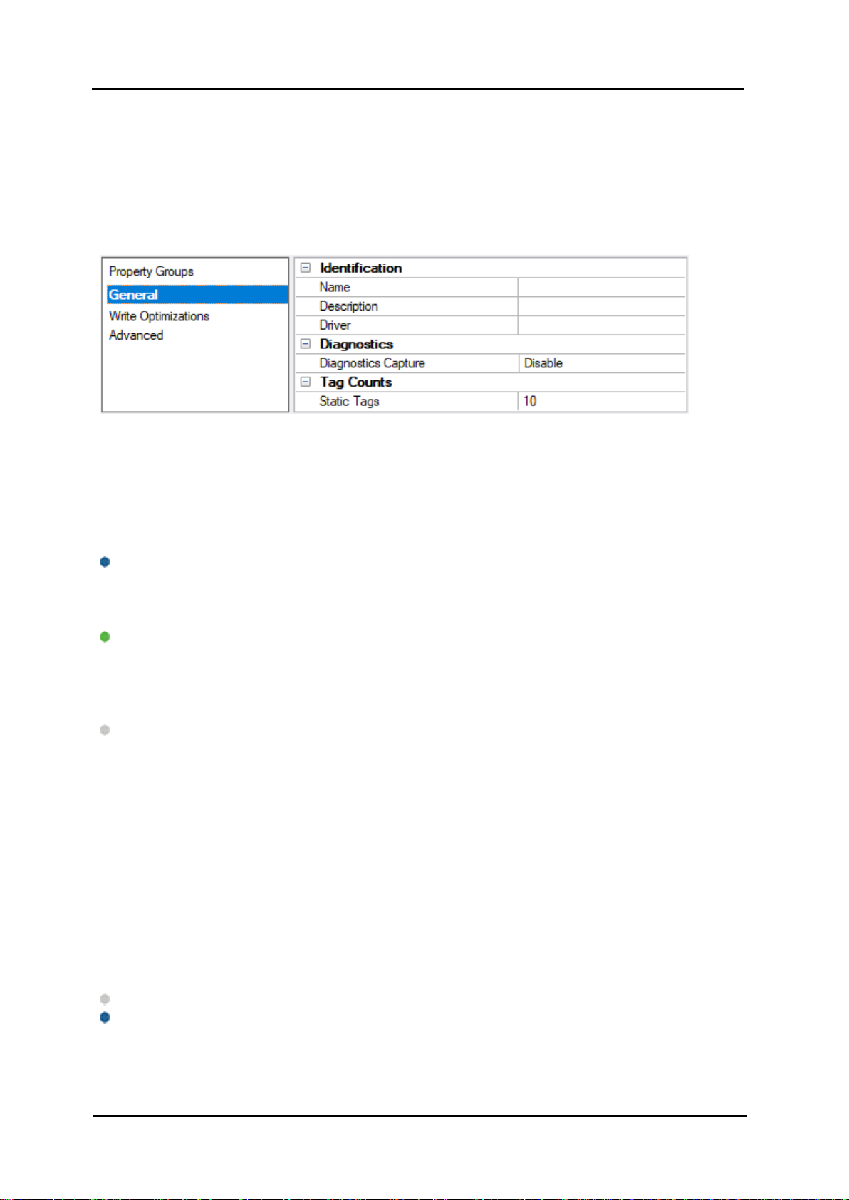
Channel Properties — General
This server supports the use of multiple simultaneous communications drivers. Each protocol or driver used
in a server project is called a channel. A server project may consist of many channels with the same communications driver or with unique communications drivers. A channel acts as the basic building block of an
OPClink. This group is used to specify general channel properties, such as the identification attributes and
operating mode.
Identification
Name: Specify the user-defined identity of this channel. In each server project,each channel name must be
unique. Although names can be up to 256 characters, some client applications have a limited display window
when browsing the OPC server's tag space. The channel name is part of the OPCbrowser information. The
property is required for creating a channel.
For information on reserved characters,refer to "How To... Properly Name a Channel, Device, Tag,and Tag
Group" in the server help.
Description: Specify user-defined information about this channel.
Many of these properties, including Description, have an associated system tag.
Driver: Specify the protocol / driver for this channel.This property specifies the device driver that was selected during channel creation. It is a disabled setting in the channel properties. The property is required for creating a channel.
Note:With the server's online full-time operation, these properties can be changed at any time. This
includes changing the channel name to prevent clients from registering data with the server. If a client has
already acquired an item from the server before the channel name is changed, the items are unaffected. If,
after the channel name has been changed, the client application releases the item and attempts to reacquire using the old channel name,the item is not accepted. Changes to the properties should not be made
once a large client application has been developed.Utilize proper user role and privilege management to
prevent operators from changing properties or accessing server features.
Diagnostics
Diagnostics Capture: When enabled, this option makes the channel's diagnostic information available to
OPCapplications. Because the server's diagnostic features require a minimal amount of overhead processing, it is recommended that they be utilized when needed and disabled when not. The default is disabled.
Note: This property is not available if the driver does not support diagnostics.
For moreinformation, refer to "Communication Diagnostics" and "StatisticsTags" in theserver help.
Tag Counts
www. ptc.com
Page 10
Fanuc Focas Ethernet Driver
Static Tags: Provides the total number of defined static tags at this level (device or channel). This information can be helpful in troubleshooting and load balancing.
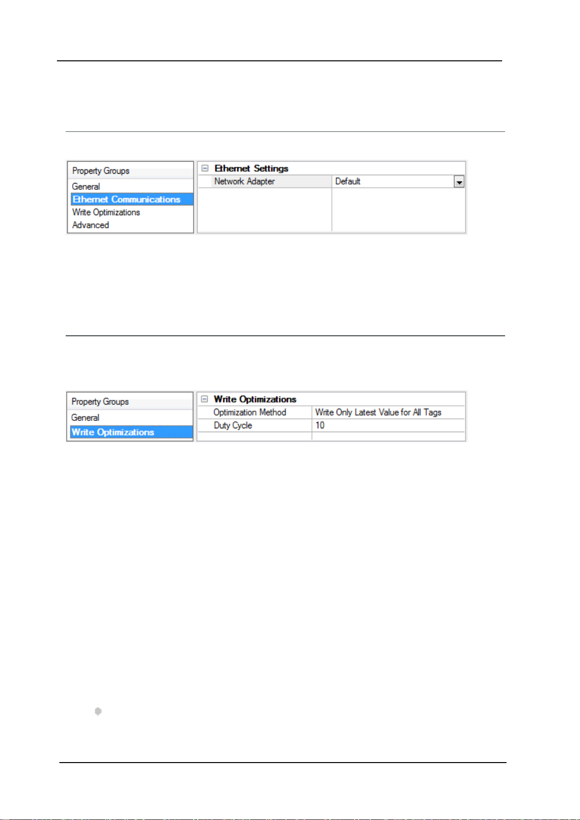
Channel Properties — Ethernet Communications
Ethernet Communication can be used to communicate with devices.
Ethernet Settings
Network Adapter: Specify the network adapter to bind.When left blank or Default is selected,the oper-
ating system selects the default adapter.
Channel Properties — Write Optimizations
10
The server must ensure that the data written from the client application gets to the device on time. Given
this goal, the server provides optimization properties to meet specific needs or improve application responsiveness.
Write Optimizations
Optimization Method: Controls how write data is passed to the underlying communications driver. The
options are:
l Write All Values for All Tags: This option forces the server to attempt to write every value to the
controller. In this mode,the server continues to gather write requests and add them to the server's
internal write queue. The server processes the write queue and attempts to empty it by writing data
to the device as quickly as possible. This mode ensures that everything written from the client applications is sent to the target device. This mode should be selected if the write operation order or the
write item's content must uniquely be seen at the target device.
l Write Only Latest Value for Non-Boolean Tags:Many consecutive writes to the same value can
accumulate in the write queue due to the time required to actually send the data to the device. If the
server updates a write value that has already been placed in the write queue, far fewer writes are
needed to reach the same final output value. In this way, no extra writes accumulate in the server's
queue. When the user stops moving the slide switch, the value in the device is at the correct value at
virtually the same time. As the mode states, any value that is not a Boolean value is updated in the
server's internal write queue and sent to the device at the next possible opportunity. This can greatly
improve the application performance.
Note:This option does not attempt to optimize writes to Boolean values.It allows users to optimize
www. ptc.com
Page 11
11
Fanuc FocasEthernet Driver
the operation of HMIdata without causing problems with Boolean operations, such as a momentary
push button.
l Write Only Latest Value for All Tags: This option takes the theory behind the second optimization
mode and applies it to all tags. It is especially useful if the application only needs to send the latest
value to the device. This mode optimizes all writes by updating the tags currently in the write queue
before they are sent. This is the default mode.
Duty Cycle: is used to control the ratio of write to read operations. The ratio is always based on one read for
every one to ten writes. The duty cycle is set to ten by default,meaning that ten writes occur for each read
operation. Although the application is performing a large number of continuous writes, it must be ensured
that read data is still given time to process. A setting of one results in one read operation for every write
operation. If there are no write operations to perform, reads are processed continuously. This allows optimization for applications with continuous writes versus a more balanced back and forth data flow.
Note:It is recommended that the application be characterized for compatibility with the write optimization
enhancements before being used in a production environment.
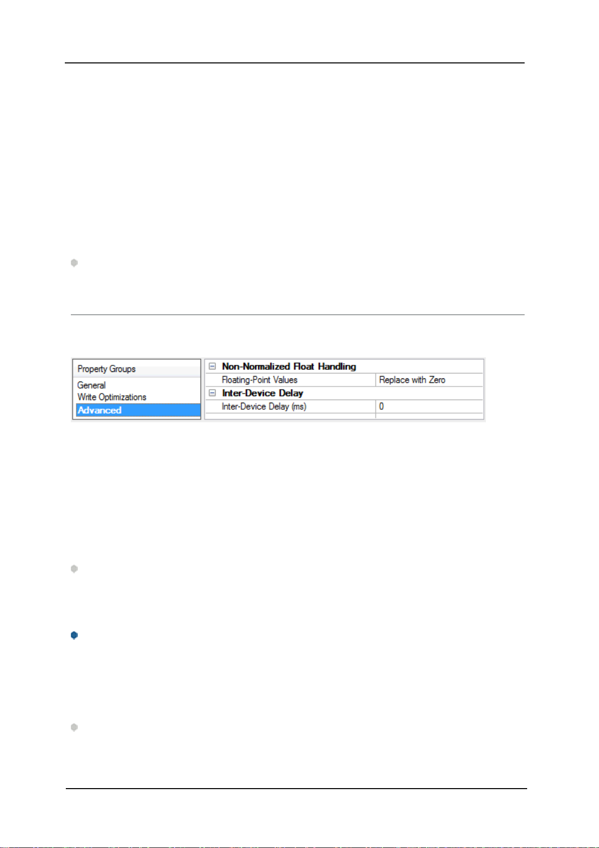
Channel Properties — Advanced
This group is used to specify advanced channel properties.Not all drivers support all properties; so the
Advanced group does not appear for those devices.
Non-Normalized Float Handling:A non-normalized value is defined as Infinity, Not-a-Number (NaN), or as
a Denormalized Number. The default is Replace with Zero. Drivers that have native float handling may
default to Unmodified. Non-normalized float handling allows users to specify how a driver handles non-normalized IEEE-754 floating point data.Descriptions of the options are as follows:
l Replace with Zero: This option allows a driver to replace non-normalized IEEE-754 floating point val-
ues with zero before being transferred to clients.
l Unmodified: This option allows a driver to transfer IEEE-754 denormalized, normalized, non-num-
ber, and infinity values to clients without any conversion or changes.
Note: This property is disabled if the driver does not support floating-point values or if it only supports the
option that is displayed. According to the channel's float normalization setting, only real-time driver tags
(such as values and arrays) are subject to float normalization. For example,EFM data is not affected by this
setting.
For moreinformation on the floating-point values, refer to "How To ... Work with Non-Normalized FloatingPoint Values" in theserver help.
Inter-Device Delay: Specify the amount of time the communications channel waits to send new requests to
the next device after data is received from the current device on the same channel.Zero (0) disables the
delay.
Note: This property is not available for all drivers, models, and dependent settings.
www. ptc.com
Page 12

Fanuc Focas Ethernet Driver
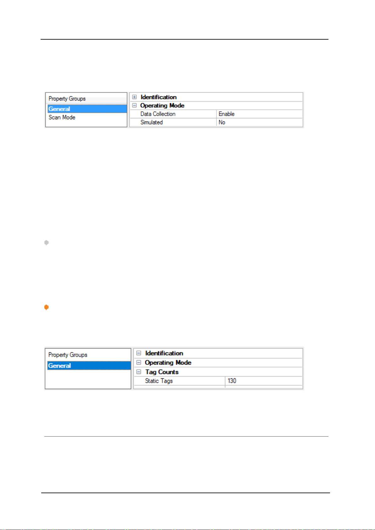
Device Properties — General
A device represents a single target on a communications channel.If the driver supports multiple controllers,
users must enter a device ID for each controller.
Identification
Name: Specify the name of the device. It is a logical user-defined name that can be up to 256 characters
long and may be used on multiple channels.
Note:Although descriptive names are generally a good idea, some OPCclient applications may have a
limited display window when browsing the OPCserver's tag space. The device name and channel name
become part of the browse tree information as well. Within an OPCclient, the combination of channel name
and device name would appear as "ChannelName.DeviceName".
For moreinformation, refer to "How To... Properly Namea Channel, Device,Tag,and TagGroup" in server
help.
12
Description: Specify the user-defined information about this device.
Many of these properties,including Description, have an associated system tag.
Channel Assignment: Specify the user-defined name of the channel to which this device currently belongs.
Driver: Selected protocol driver for this device.
Model: Specify the type of device that is associated with this ID. The contents of the drop-down menu
depend on the type of communications driver being used. Models that are not supported by a driver are disabled. If the communications driver supports multiple device models, the model selection can only be
changed when there are no client applications connected to the device.
Note: If the communication driver supports multiple models,users should try to match the model selection to the physical device. If the device is not represented in the drop-down menu, select a model that conforms closest to the target device.Some drivers support a model selection called "Open," which allows users
to communicate without knowing the specific details of the target device.For more information, refer to the
driver help documentation.
ID: Specify the device's driver-specific station or node. The type of ID entered depends on the communications driver being used. For many communication drivers, the ID is a numeric value. Drivers that support a Numeric ID provide users with the option to enter a numeric value whose format can be changed to
suit the needs of the application or the characteristics of the selected communications driver. The format is
set by the driver by default. Options include Decimal, Octal, and Hexadecimal.
Note:If the driver is Ethernet-based or supports an unconventional station or node name,the device's
TCP/IPaddress may be used as the device ID. TCP/IPaddresses consist of four values that are separated by
periods, with each value in the range of 0 to 255. Some device IDs are string based. There may be additional
www. ptc.com
Page 13
13
properties to configure within the ID field, depending on the driver. For moreinformation, refer to the driver's
help documentation.
Fanuc FocasEthernet Driver
Operating Mode
Data Collection: This property controls the device's active state. Although device communications are
enabled by default, this property can be used to disable a physical device. Communications are not attempted when a device is disabled. From a client standpoint, the data is marked as invalid and write operations
are not accepted. This property can be changed at any time through this property or the device system tags.
Simulated: Place the device into or out of Simulation Mode. In this mode, the driver does not attempt to
communicate with the physical device, but the server continues to return valid OPCdata.Simulated stops
physical communications with the device, but allows OPCdata to be returned to the OPCclient as valid data.
While in Simulation Mode, the server treats all device data as reflective:whatever is written to the simulated
device is read back and each OPCitem is treated individually. The item's memory map is based on the group
Update Rate. The data is not saved if the server removes the item (such as when the server is reinitialized).
The default is No.
Notes:
1. This System tag (_Simulated) is read only and cannot be written to for runtime protection. The System
tag allows this property to be monitored from the client.
2. In Simulation mode, the item's memory map is based on client update rate(s) (Group Update Rate for
OPCclients or Scan Rate for native and DDEinterfaces). This means that two clients that reference
the same item with different update rates return different data.
Simulation Mode is for test and simulation purposes only. It should never be used in a production envir-
onment.
Tag Counts
Static Tags: Provides the total number of defined static tags at this level (device or channel). This inform-
ation can be helpful in troubleshooting and load balancing.
Device Properties — Scan Mode
The Scan Mode specifies the subscribed-client requested scan rate for tags that require device communications. Synchronous and asynchronous device reads and writes are processed as soon as possible;
unaffected by the Scan Mode properties.
www. ptc.com
Page 14
Fanuc Focas Ethernet Driver
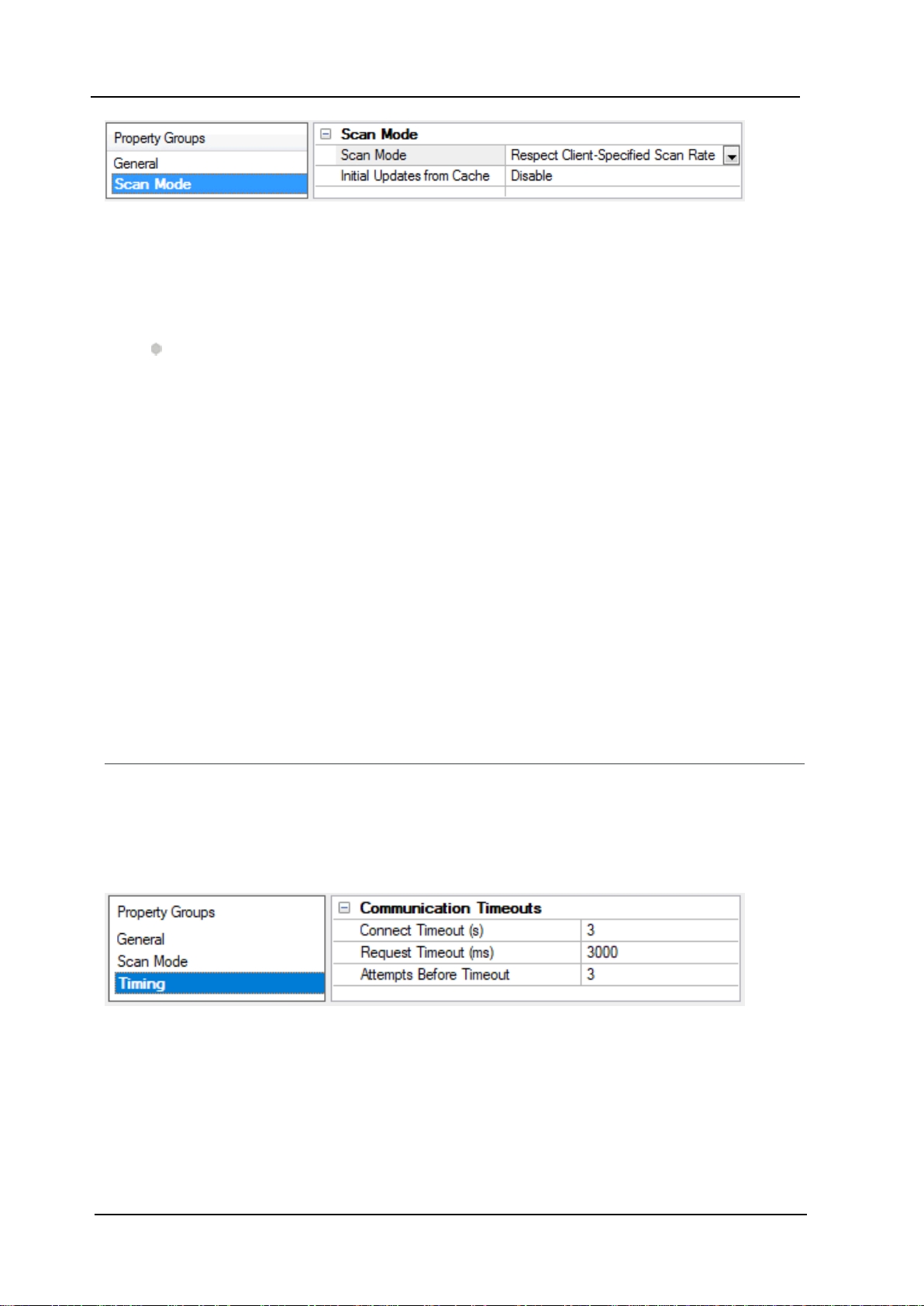
Scan Mode: Specify how tags in the device are scanned for updates sent to subscribing clients.Descriptions
of the options are:
l Respect Client-Specified Scan Rate: This mode uses the scan rate requested by the client.
l Request Data No Faster than Scan Rate: This mode specifies the value set as the maximum scan
rate.The valid range is 10 to 99999990 milliseconds.The default is 1000 milliseconds.
Note: When the server has an active client and items for the device and the scan rate value is
increased, the changes take effect immediately. When the scan rate value is decreased, the changes
do not take effect until all client applications have been disconnected.
l Request All Data at Scan Rate: This mode forces tags to be scanned at the specified rate for sub-
scribed clients. The valid range is 10 to 99999990 milliseconds. The default is 1000 milliseconds.
l Do Not Scan, Demand Poll Only: This mode does not periodically poll tags that belong to the
device nor perform a read to get an item's initial value once it becomes active. It is the OPCclient's
responsibility to poll for updates, either by writing to the _DemandPoll tag or by issuing explicit device
reads for individual items. For more information, refer to "Device Demand Poll" in server help.
l Respect Tag-Specified Scan Rate: This mode forces static tags to be scanned at the rate specified
in their static configuration tag properties. Dynamic tags are scanned at the client-specified scan
rate.
14
Initial Updates from Cache: When enabled,this option allows the server to provide the first updates for
newly activated tag references from stored (cached) data. Cache updates can only be provided when the
new item reference shares the same address, scan rate,data type,client access,and scaling properties. A
device read is used for the initial update for the first client reference only. The default is disabled; any time a
client activates a tag reference the server attempts to read the initial value from the device.
Device Properties — Timing
The device Timing properties allow the driver's response to error conditions to be tailored to fit the application's needs. In many cases, the environment requires changes to these properties for optimum performance. Factors such as electrically generated noise, modem delays, and poor physical connections can
influence how many errors or timeouts a communications driver encounters. Timing properties are specific
to each configured device.
Communications Timeouts
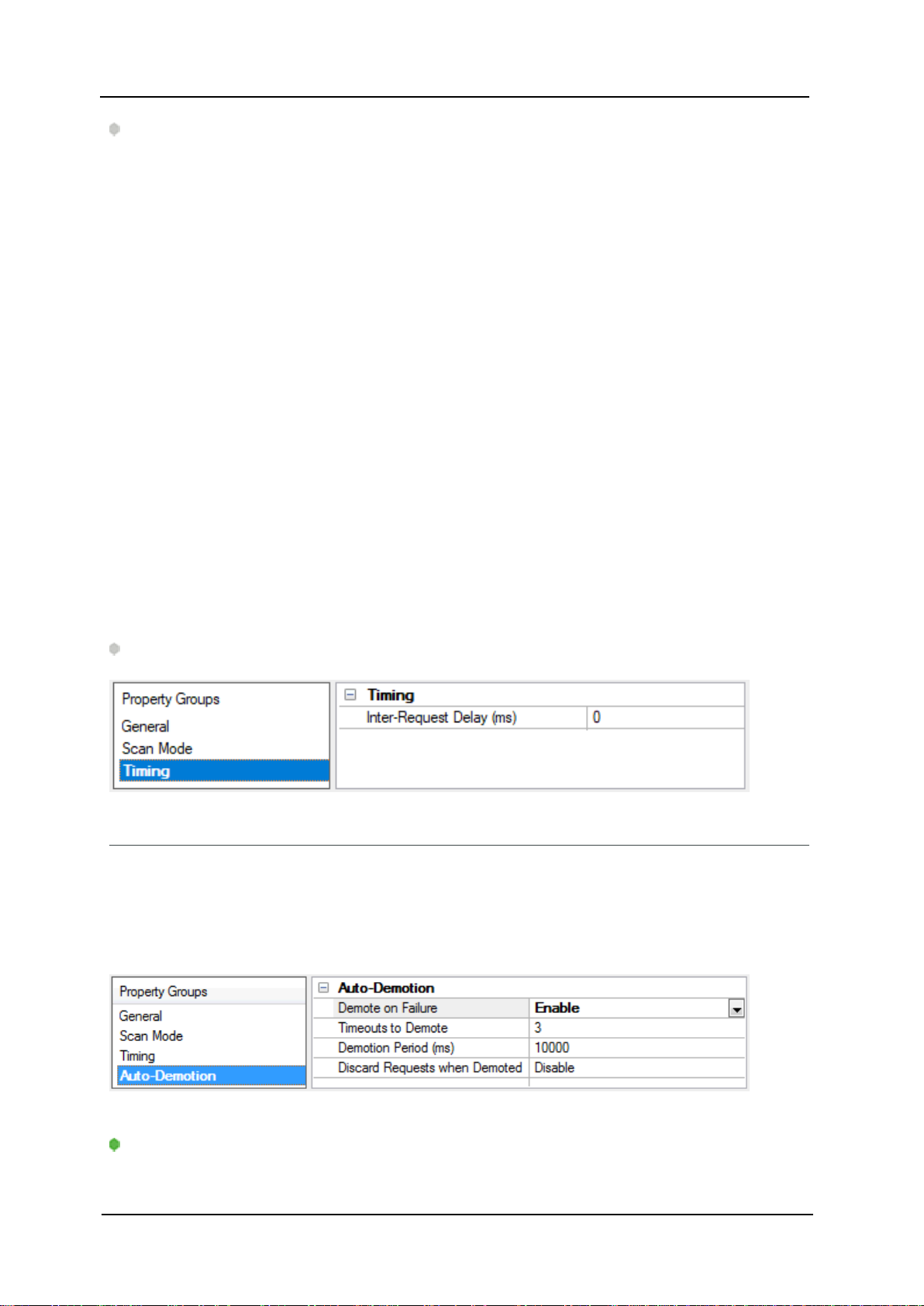
Connect Timeout: This property (which is used primarily by Ethernet based drivers) controls the amount of
time required to establish a socket connection to a remote device. The device's connection time often takes
longer than normal communications requests to that same device.The valid range is 1 to 30 seconds. The
default is typically 3 seconds, but can vary depending on the driver's specific nature. If this setting is not supported by the driver,it is disabled.
www. ptc.com
Page 15
15
Note:Due to the nature of UDP connections, the connection timeout setting is not applicable when com-
municating via UDP.
Request Timeout: Specify an interval used by all drivers to determine how long the driver waits for a
response from the target device to complete. The valid range is 50 to 9,999,999 milliseconds (167.6667
minutes). The default is usually 1000 milliseconds,but can vary depending on the driver. The default timeout
for most serial drivers is based on a baud rate of 9600 baud or better. When using a driver at lower baud
rates,increase the timeout to compensate for the increased time required to acquire data.
Attempts Before Timeout: Specify how many times the driver issues a communications request before considering the request to have failed and the device to be in error. The valid range is 1 to 10.The default is typically 3, but can vary depending on the driver's specific nature. The number of attempts configured for an
application depends largely on the communications environment. This property applies to both connection
attempts and request attempts.
Fanuc FocasEthernet Driver
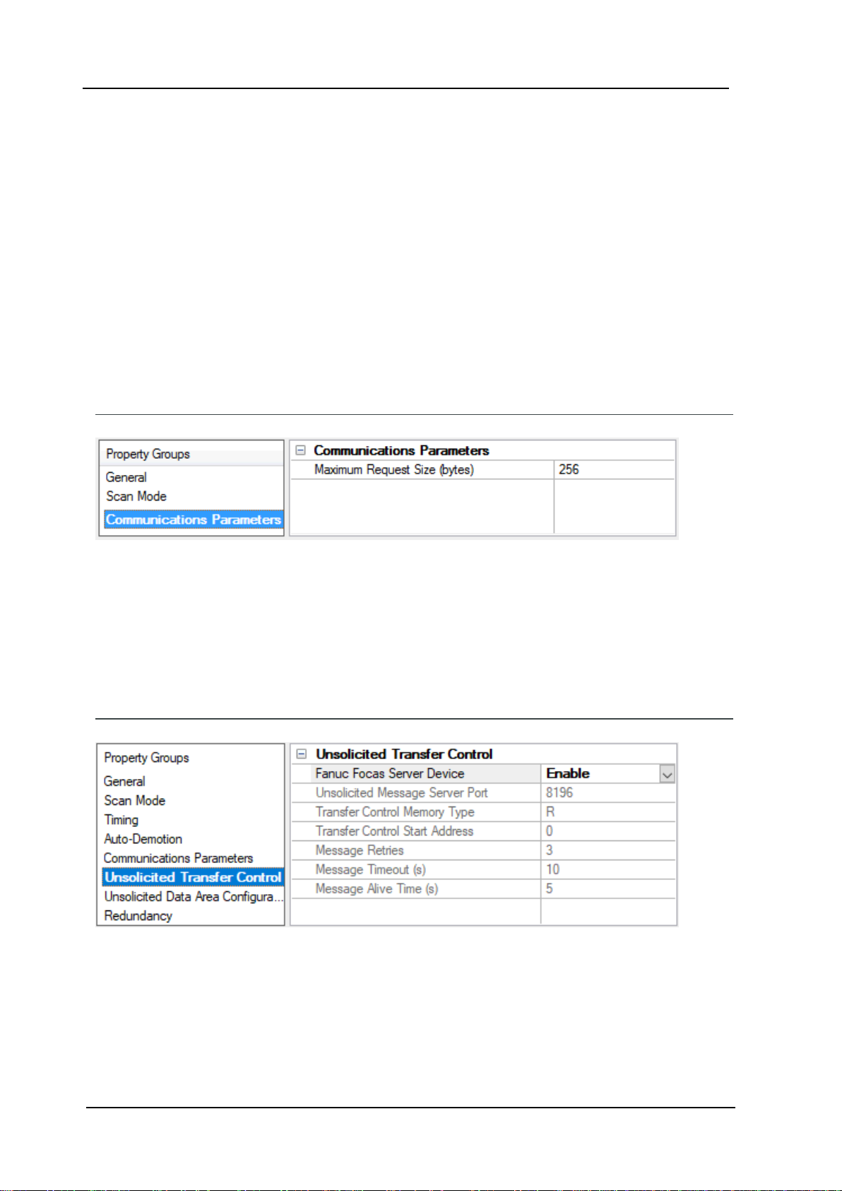
Timing
Inter-Request Delay: Specify how long the driver waits before sending the next request to the target
device. It overrides the normal polling frequency of tags associated with the device, as well as one-time
reads and writes. This delay can be useful when dealing with devices with slow turnaround times and in
cases where network load is a concern.Configuring a delay for a device affects communications with all
other devices on the channel. It is recommended that users separate any device that requires an interrequest delay to a separate channel if possible.Other communications properties (such as communication
serialization) can extend this delay. The valid range is 0 to 300,000 milliseconds;however, some drivers may
limit the maximum value due to a function of their particular design. The default is 0, which indicates no
delay between requests with the target device.
Note:Not all drivers support Inter-Request Delay. This setting does not appear if it is not available.
Device Properties — Auto-Demotion
The Auto-Demotion properties can temporarily place a device off-scan in the event that a device is not
responding.Byplacing a non-responsive device offline for a specific time period, the driver can continue to
optimize its communications with other devices on the same channel.After the time period has been
reached, the driver re-attempts to communicate with the non-responsive device. If the device is responsive,
the device is placed on-scan; otherwise, it restarts its off-scan time period.
Demote on Failure: When enabled, the device is automatically taken off-scan until it is responding again.
Tip:Determine when a device is off-scan by monitoring its demoted state using the _AutoDemoted sys-
tem tag.
www. ptc.com
Page 16
Fanuc Focas Ethernet Driver
Timeouts to Demote: Specify how many successive cycles of request timeouts and retries occur before the
device is placed off-scan. The valid range is 1 to 30 successive failures. The default is 3.
Demotion Period:Indicate how long the device should be placed off-scan when the timeouts value is
reached. During this period,no read requests are sent to the device and all data associated with the read
requests are set to bad quality. When this period expires,the driver places the device on-scan and allows for
another attempt at communications. The valid range is 100 to 3600000 milliseconds. The default is 10000
milliseconds.
Discard Requests when Demoted: Select whether or not write requests should be attempted during the
off-scan period.Disable to always send write requests regardless of the demotion period. Enable to discard
writes; the server automatically fails any write request received from a client and does not post a message
to the Event Log.
Device Properties — Communications Parameters
16
TCP/IP Port: Specify the TCP/IPport number that the remote device is configured to use. The default setting
is 8193.
Maximum Request Size: Specify the number of bytes that may be requested from a device at one time.To
refine the driver's performance, configure the request size to one of the following settings:8,16, 32, 64, 128,
256,or 512 bytes. The default setting is 256 bytes.
Device Properties — Unsolicited Transfer Control
Fanuc Focas Server Device: This option should be enabled if the device receives unsolicited data from the
CNC. All tags belonging to a Fanuc Focus Server device read data cached in the driver,not directly from the
CNC. The Fanuc Focus Server device's tags displays a value of zero until it receives its first unsolicited data
update.When disabled, all tags belonging to the device read and write directly to the CNC.The default setting is disabled.
www. ptc.com
Page 17
17
Unsolicited Message Server Port: Specify the port that the unsolicited message server application has
been configured to use. The default setting is 8196.
Transfer Control Memory Type:Specify the registers' PMC memory type for unsolicited message transfer
control. Options include R(internal relay) and E(extended relay). The default setting is R.
Transfer Control Start Address:Specify the start address of the registers used for unsolicited message
transfer control. The valid range is 0 to 7999,although the actual range of valid addresses depends on the
hardware. The default setting is 0.
Message Retries: Specify the number of times that the CNCshould retry sending unsolicited messages. The
valid range is 0 to 10.The default setting is 3.
Message Timeout: Specify the unsolicited message timeout,which is the amount of time that the CNC waits
for the driver to respond to an unsolicited message. The valid range is 0 to 30.The default setting is 10
seconds.
Message Alive Time: Specify the unsolicited message alive time,which is the amount of time that the CNC
retains an unsolicited message for the driver to read. This setting must be less than the message timeout.
The valid range is 0 to 30.The default setting is 5 seconds.
Fanuc FocasEthernet Driver
See Also:Unsolicited Messaging
Device Properties — Unsolicited Data Areas
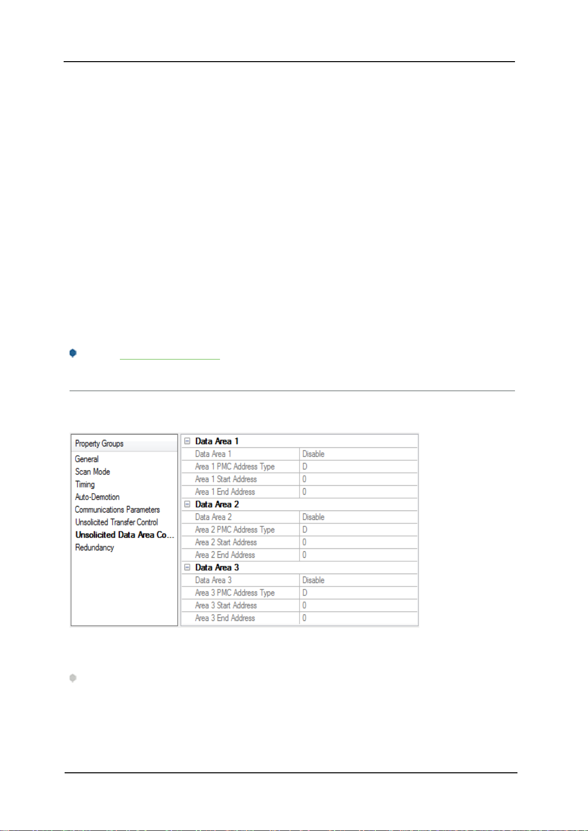
Users can configure up to three areas in PMCmemory for unsolicited messaging. These areas' data content
is sent to the driver in each unsolicited message. As such, these areas should be made as small as possible.
Data Area n
Note:All tags that are created for a Fanuc Focus server device are validated according to the configured
data areas.For example, if a Fanuc Focus Server device is configured with a single area with D1000 to
D1100, then a tag with address D1000 would be valid,but tags with addresses D1101 or C0001 would be
invalid. All tags belonging to a Fanuc Focus Server device are Read Only.
www. ptc.com
Page 18
Fanuc Focas Ethernet Driver
l Data Area n:When enabled,this data area is in use.
l PMC Address Type:Specify the area's PMCaddress type. The default setting is D. Supported types
include the following:
l G:Signal to PMC->CNC
l F:Signal to CNC->PMC
l Y:Signal to PMC->machine
l X: Signal to machine->PMC
l A:Message demand
l R:Internal relay
l T:Changeable timer
l K:Keep relay
l C:Counter
l D:Data table
l Start Address:Specify an area's start address.The valid range is 0 and 7999,although the actual
range of valid addresses depends on the hardware. The default setting is 0.
l End Address:Specify an area's end address. The valid range is 0 and 7999,although the actual
range of valid addresses depends on the hardware. The total number of bytes must not exceed 1430,
1414, or 1398 for areas 1, 2, or 3 respectively. The default value is 0.
18
See Also: Unsolicited Messaging
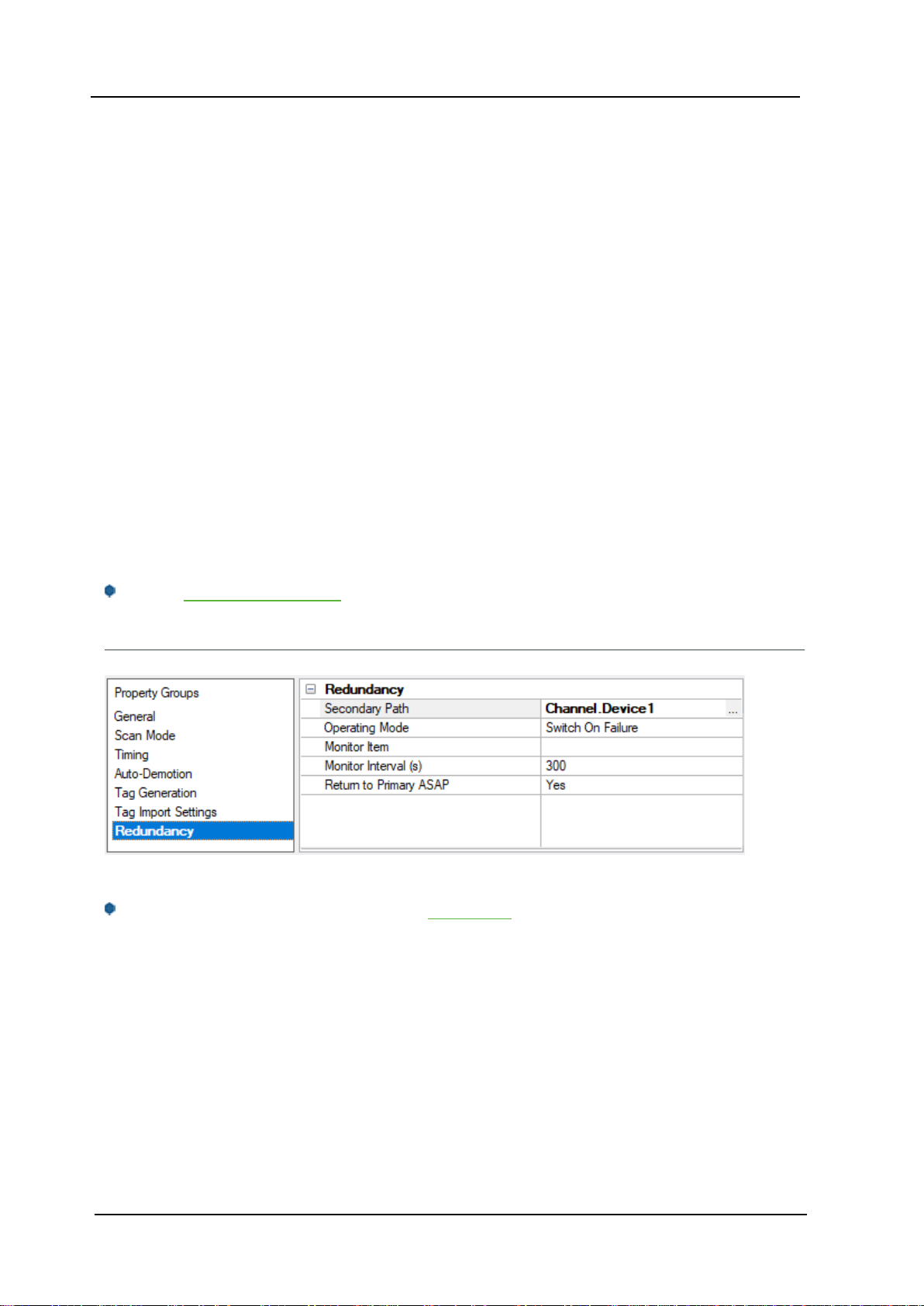
Device Properties — Redundancy
Redundancy is available with the Media-Level Redundancy Plug-In.
Consult thewebsite,a salesrepresentative,or the user manual for more information.
www. ptc.com
Page 19

19
Fanuc FocasEthernet Driver
Unsolicited Messaging
Before configuring a system for unsolicited messaging, it is important that users understand how the various hardware and software components work together to transfer data. These components include one or
more CNCcontrollers equipped with Fast Ethernet communications boards, firmware that supports unsolicited messaging, and a ladder program. To receive unsolicited data,a host computer must be equipped
with the OPCserver, its Fanuc Focas Ethernet Driver, the Focas 1 Data Window Library software, and the
Unsolicited Message Server. Data can be read from the OPCserver with OPCor DDEclient applications running on the host or remote computer. For more information, refer to Additional Software Requirements.
During an unsolicited messaging session, the controller is only in direct communication with the Unsolicited
Message Server.The message server notifies the driver when the controller makes a request to send unsolicited data. The Focas 1 Data Window Library allows the driver to receive the unsolicited data via the message server,and also enables direct communications with the controllers for starting and ending unsolicited
messaging sessions.
Note:If unsolicited messaging is not used, the driver uses the library to issue read and write requests directly to the controller. It is possible to simultaneously use both types of communication with a controller by
creating a Fanuc Focus Server and a non-server device in the OPCserver project.
Unsolicited Data Transmission
Ladder programs coordinate the transfer of unsolicited data from their respective controllers and must be
tailored to each application. For more information on unsolicited data transmission, refer to theinstructions
below.
1. To start, the ladder program places the message contents in a designated area of the PMCmemory.
Once the message is prepared, the ladder controls the data transmission by setting and monitoring
bits in the Unsolicited Transfer Control area of PMC memory.
2. To trigger the unsolicited message transmission,the ladder sets the "REQ" (request to send) transfer
control bit. The controller sends an "Unsolicited data ready" notification to the message server immediately after.
3. The message server relays the notification to the driver, which then responds by issuing a "Read
unsolicited message" command to the message server.
4. The driver receives the unsolicited message data in response to this command,and then replies to
the data ready notification with a response code indicating success or failure. The message server
then passes this response code to the controller.
5. When the controller receives the response code,it copies it to the "RES_CODE" memory area. The
controller sets the "RES" (response ready) bit to indicate that the transaction completed immediately
after.
Note:The ladder program must be designed to detect when the RESbit has been set.Once it
detects that the RESbit has been set, it can read the response code and react as needed. If the data
fails to reach the driver,the controller will place its own response code that describes the problem in
RES_CODEand set the RESbit.
6. Once the ladder has read the response code, it must clear the REQbit to ready the system for the
next message.
PMCMemory
www. ptc.com
Page 20
Fanuc Focas Ethernet Driver
The PMC memory area included in unsolicited messages is defined with the Fanuc Focas Ethernet Driver.
The driver transfers these area properties to the controller at the start of an unsolicited messaging session.
Data from the range of all areas is included each time an unsolicited message is sent. As such, these areas
should be made as small as possible.The ladder program must be written to use the exact address ranges
specified in the driver configuration.
Unsolicited data transmission is coordinated between the ladder program and communications board via 2
bytes of PMC Ror Ememory. This transfer control area is defined with the Fanuc Focas Ethernet Driver . The
transfer control area properties are then sent to the controller along with the data area properties when an
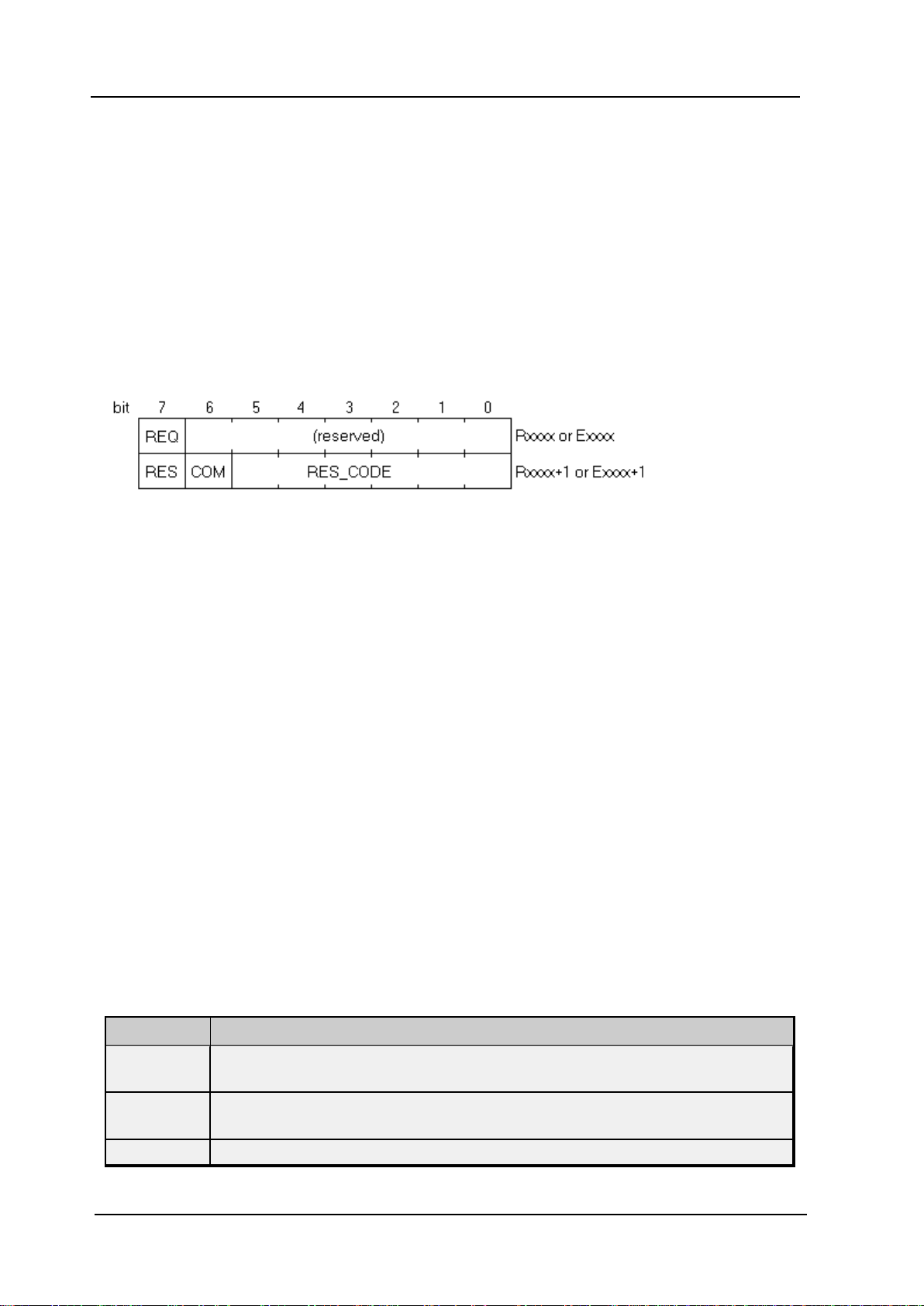
unsolicited messaging session starts. The ladder program must be written to use the specific addresses specified in the driver configuration. The various bits in the transfer control area,with starting address xxxx,
have the following locations and meanings:
20
REQ
Rxxxx.7 (or Exxxx.7)
After the ladder program constructs a message, it must set this bit to 1. This signals the communications
board to issue a notification that a new message is ready to be read.
COM
Rxxxx+1.6 (or Exxxx+1.6)
The communications board sets this bit to 1 when message transmission begins. The communications board
sets this bit back to 0 immediately before it sets RESto 1, and places the response code in RES_CODE.
RES
Rxxxx+1.7 (or Exxxx+1.7)
The communications board sets this bit to 1 immediately after message transmission completes. When the
ladder program detects that this bit is set to 1, it can read the response code from RES_CODE.The ladder
then acts depending on the value of RES_CODE.Once this is done, the ladder must set REQback to 0. This
causes the communications board to clear RES_CODE and set the bit back to 0. Then the communications
board is ready to perform the next unsolicited transaction.
RES_CODE
Rxxxx+1.0 to Rxxxx+1.5 (or Exxxx+1.0 to Exxxx+1.5)
The result of the unsolicited transaction is placed here. It can be a code passed down from the driver,or a
code set by the communications board if there was a communications failure.The possible values are displayed in the table below.
RES_CODE Meaning
0x00
0x01
0x02 The unsolicited message server is not running.
Success. The communications board did not detect any failures in communication, and
the driver reported that it processed the received data successfully.
The transmission control properties are invalid or the unsolicited messaging session
was not started.
www. ptc.com
Page 21

21
RES_CODE Meaning
0x03 The CNCfailed to transmit message.
0x04 The CNCfailed to receive response.
0x05 The transmission retry count was exceeded.
0x06 The CNCfailed to construct the message data.
0x07 The CNCreceived an invalid packet.
0x08 The CNCaccepted termination of unsolicited messaging session.
0x10 The driver experienced a Focas 1 Library error while reading message.
0x11
0x21
0x22
0x23 The CNCfailed in writing the received message to the PC.
0x24 The timeout period and retry count have expired.
0x25 Illegal data was included in the received message.
The driver found the message data to be invalid or experienced other problems while
processing message data.
The PCapplication to receive the message does not exist, though the message was
received by the PC.Either the OPCserver or this driver is not running.
The PCapplication to receive the message was not recognized by the unsolicited message server,though the message was received by the PC.The unsolicited message
server may need be restarted, or there may have been a problem when the driver was
starting the unsolicited messaging session.
Fanuc FocasEthernet Driver
The Fanuc Focas Ethernet Driver stores unsolicited data in a memory cache. The OPCserver makes this
data visible to client applications via tags, whose addresses must be the same as the controller's data
source. For example, if an unsolicited data area is configured to include the byte at D1000, then a tag with an
address of D1000 must be used to view the data. These tags show the last values sent to the driver, which
may not necessarily be the current values in the controller.Topoll current values directly from the controller, users would need additional tags belonging to a non-server device. Fanuc Focus Server device tags
display a value of zero until the driver receives its first unsolicited data update from the controller.
Notes:
1. In addition to data ready notifications, the Unsolicited Message Server also apprises the driver of
other important events. These include CNCpower up,CNCpower down, Unsolicited Message Server
shutdown, and communications error notifications.The driver responds to each of these events in
such a way that communication with the hardware is maintained,if possible.
2. The device's _System._Error Tag is set if the driver fails to start an unsolicited messaging session,or
restarts the session after detecting a communications problem. Tags that belong to a Fanuc Focus
Server device in an error state will continue to display the last value received from the device or the
initial value of zero.
www. ptc.com
Page 22
Fanuc Focas Ethernet Driver
Optimizing Communications
The Fanuc Focas Ethernet Driver has been designed to provide the best performance with the least amount
of impact on the system's overall performance.While the driver is fast, there are a couple of guidelines that
can be used to control and optimize the application and gain maximum performance.
This server refers to communications protocols like Fanuc Focas Ethernet as a channel.Each channel
defined in the application represents a separate path of execution in the server. Once a channel has been
defined, a series of devices must then be defined under that channel.Each of these devices represents a
single Fanuc Focas controller from which data is collected. While this approach to defining the application
provides a high level of performance, it won't take full advantage of the Fanuc Focas Ethernet Driver or the
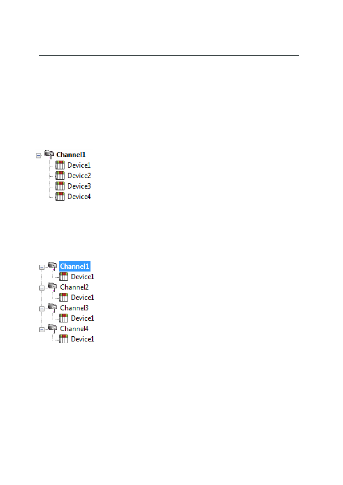
network. An example of how the application may appear when configured using a single channel is shown
below.
Each device appears under a single channel. In this configuration, the driver must
move from one device to the next as quickly as possible to gather information at an
effective rate. As more devices are added or more information is requested from a
single device, the overall update rate begins to suffer.
22
If the Fanuc Focas Ethernet Driver could only define one single channel, then the example shown above
would be the only option available; however, the driver can define up to 256 channels. Using multiple channels distributes the data collection workload by simultaneously issuing multiple requests to the network. An
example of how the same application may appear when configured using multiple channels to improve performance is shown below.
Each device can be defined under its own channel. In this configuration, a single
path of execution is dedicated to the task of gathering data from each device. If the
application has fewer devices, it can be optimized exactly how it is shown here.
There is performance improvement even if the application has more devices.
While fewer devices may be ideal,the application still benefits from additional channels.Although spreading the device load across all channels causes the server to
move from device to device again, it can now do so with far less devices to process
on a single channel.
Request Size can also affect the Fanuc Focas Ethernet Driver performance.The request size refers to the
number of bytes that may be requested from a device at one time and is available on every defined device.
To refine the driver's performance, configure the request size to one of the following settings:8,16, 32, 64,
128,256, or 512 bytes. Depending on the model of the device being used, the setting chosen for request size
can dramatically affect the application. The default value of 256 bytes is recommended. If the application
consists of large requests for consecutively ordered data, try increasing the request size setting for the
device. For more information, refer to Setup.
www. ptc.com
Page 23

23
Data Types Description
Data Type Description
Boolean Single bit
Unsigned 8-bit value
Byte
bit 0 is the low bit
bit 7 is the high bit
Unsigned 16-bit value
Fanuc FocasEthernet Driver
Word
Short
DWord
Long
Float 32-bit floating point value
String Null terminated ASCII string
bit 0 is the low bit
bit 15 is the high bit
Signed 16-bit value
bit 0 is the low bit
bit 14 is the high bit
bit 15 is the sign bit
Unsigned 32-bit value
bit 0 is the low bit
bit 31 is the high bit
Signed 32-bit value
bit 0 is the low bit
bit 30 is the high bit
bit 31 is the sign bit
www. ptc.com
Page 24

Fanuc Focas Ethernet Driver
Address Descriptions
Address specifications may vary depending on the model in use. Select a link from the following list to obtain
specific address information for the model of interest.
Note: If the model of interest is listed as supported but is not selectable, use the Open model.
Series 15i
Series 16i
Series 18i
Series 21i
Power Mate i
Open
Series 15i
The following addresses are supported for this model. Not all address ranges may be valid for the particular
device being used. For more information,refer to the specific device's documentation. To jump to a specific
section, select a link from the list below.
24
CNC Data
Arrays
Strings
PMCData
The default data types for dynamically defined DDE tags are shown in bold.
Address Type Range Data Type Access
A (Message demand)
C(Counter)
D (Data table)
F(Signal to CNC->PMC)
G (Signal to PMC->CNC)
A00000-A00124
A00000-A00123
A00000-A00121
Axxxxx.0-Axxxxx.7
C00000-C00199
C00000-C00198
C00000-C00196
Cxxxxx.0-Cxxxxx.7
D00000-D09999
D00000-D09998
D00000-D09996
Dxxxxx.0-Dxxxxx.7
F00000-F00511
F00000-F00510
F00000-F00508
Fxxxxx.0-Fxxxxx.7
G00000-G00511
G00000-G00510
G00000-G00508
Gxxxxx.0-Gxxxxx.7
Byte,Char
Word, Short
DWord, Long, Float
Boolean
Byte,Char
Word, Short
DWord, Long, Float
Boolean
Byte,Char
Word, Short
DWord, Long, Float
Boolean
Byte,Char
Word, Short
DWord, Long, Float
Boolean
Byte,Char
Word, Short
DWord, Long, Float
Boolean
Read/Write
Read/Write
Read/Write
Read Only
Read/Write
www. ptc.com
Page 25

25
Fanuc FocasEthernet Driver
Address Type Range Data Type Access
K00000-K00909
K(Keep relay)
R(Internal relay)
T (Changeable timer)
X(Signal to machine->PMC)
Y(Signal to PMC->machine)
Custom Macro Value (common range) #0100-#0999 Float, Double Read/Write
Custom Macro Value (local range) #0001-#0033 Float, Double Read Only
Custom Macro Value (system range) #1000-#9999 Float, Double Read/Write
K00000-K00908
K00000-K00906
Kxxxxx.0-Kxxxxx.7
R00000-R09199
R00000-R09198
R00000-R09196
Rxxxxx.0-Rxxxxx.7
T00000-T00299
T00000-T00298
T00000-T00296
Txxxxx.0-Txxxxx.7
X00000-X00127
X00000-X00126
X00000-X00124
Xxxxxx.0-Xxxxxx.7
Y00000-Y00127
Y00000-Y00126
Y00000-Y00124
Yxxxxx.0-Yxxxxx.7
Byte,Char
Word, Short
DWord, Long, Float
Boolean
Byte,Char
Word, Short
DWord, Long, Float
Boolean
Byte,Char
Word, Short
DWord, Long, Float
Boolean
Byte,Char
Word, Short
DWord, Long, Float
Boolean
Byte,Char
Word, Short
DWord, Long, Float
Boolean
Read/Write
Read/Write
Read/Write
Read Only
Read/Write
CNC Data
Status Info Tags
Tool Offset
Workpiece Zero Offset
Parameter Read Values
Alarms Values
Diagnostic Values
Path Value
Read Axis Data Values
Program Value
Program Name
Read Dynamic2 Data Values
Read Timer Data Values
Read Alarm Messages
Arrays
Arrays are supported for all PMC addresses,except for Custom Macros in the system range and where
Boolean or string data types are used.Tool Offset data cannot be addressed as an array. The syntax for
declaring an array is as follows:
Mxxxx[cols]with assumed row count of 1.
www. ptc.com
Page 26

Fanuc Focas Ethernet Driver
Mxxxxx[rows][cols] where M is the address type and xxxxx is the byte offset of the first element in the array.
Note:For all arrays, the total number of bytes being requested cannot exceed the specified request size.
Strings
All address types can be read and written to as ASCIIstrings. Each byte of memory contains one ASCIIcharacter.The length of strings can range from 1 to 120 and is entered in place of the bit number. An additional
character "M" is appended to the address to distinguish string addresses from bit addresses.
Example
To address a string of length 100 characters, starting at D00200, enter: D00200.100 M.
Note:Use caution when modifying Word,Short, DWord, Long, and Float types. Since all addresses start at
a byte offset within the device, it is possible for the memory associated with tags to overlap. For example,
word tags D00000 and D00001 overlap at byte 1. Writing to D00000 also modifies the value held in D00001.
It is recommended that these memory types be used such that each value to be read and written to by the
driver occupy a unique range of memory in the device. For example, map 3 Word values to bytes D00000D00001, D00002-D00003, and D00004-D00005.Tags to access these values would then have addresses
D00000, D00002,and D00004 respectively, and a data type of Word.
26
Series 16i
The following addresses are supported for this model. Not all address ranges may be valid for the particular
device being used. For more information,refer to the specific device's documentation. To jump to a specific
section, select a link from the list below.
CNC Data
Arrays
Strings
Unsolicited Data
PMCData
The default data types for dynamically defined DDE tags are shown in bold.
Address Type Range Data Type Access
A (Message demand)
C(Counter)
D (Data table)
E(Extended relay)
A00000-A00124
A00000-A00123
A00000-A00121
Axxxxx.0-Axxxxx.7
C00000-C00199
C00000-C00198
C00000-C00196
Cxxxxx.0-Cxxxxx.7
D00000-D09999
D00000-D09998
D00000-D09996
Dxxxxx.0-Dxxxxx.7
E00000-E07999
E00000-E07998
Byte,Char
Word, Short
DWord, Long, Float
Boolean
Byte,Char
Word, Short
DWord, Long, Float
Boolean
Byte,Char
Word, Short
DWord, Long, Float
Boolean
Byte,Char
Word, Short
Read/Write
Read/Write
Read/Write
Read/Write
www. ptc.com
Page 27

27
Fanuc FocasEthernet Driver
Address Type Range Data Type Access
E00000-E07996
Exxxxx.0-Exxxxx.7
F00000-F02511
F(Signal to CNC->PMC)
G (Signal to PMC->CNC)
K(Keep relay)
M (Input signal from other devices)
N (Output signal from other devices)
R(Internal relay)
T (Changeable timer)
X(Signal to machine->PMC)
Y(Signal to PMC->machine)
Custom Macro Value (common range) #0100-#0999 Float,Double Read/Write
Custom Macro Value (local range) #0001-#0033 Float, Double Read Only
Custom Macro Value (system range) #1000-#9999 Float,Double Read/Write
F00000-F02510
F00000-F02508
Fxxxxx.0-Fxxxxx.7
G00000-G02511
G00000-G02510
G00000-G02508
Gxxxxx.0-Gxxxxx.7
K00000-K00909
K00000-K00908
K00000-K00906
Kxxxxx.0-Kxxxxx.7
M00000-M00511
M00000-M00510
M00000-M00508
Mxxxxx.0-Mxxxxx.7
N00000-N00511
N00000-N00510
N00000-N00508
Nxxxxx.0-Nxxxxx.7
R00000-R09119
R00000-R09118
R00000-R09116
Rxxxxx.0-Rxxxxx.7
T00000-T00299
T00000-T00298
T00000-T00296
Txxxxx.0-Txxxxx.7
X00000-X00127
X00000-X00126
X00000-X00124
Xxxxxx.0-Xxxxxx.7
Y00000-Y00127
Y00000-Y00126
Y00000-Y00124
Yxxxxx.0-Yxxxxx.7
DWord, Long, Float
Boolean
Byte,Char
Word, Short
DWord, Long, Float
Boolean
Byte,Char
Word, Short
DWord, Long, Float
Boolean
Byte,Char
Word, Short
DWord, Long, Float
Boolean
Byte,Char
Word, Short
DWord, Long, Float
Boolean
Byte,Char
Word, Short
DWord, Long, Float
Boolean
Byte,Char
Word, Short
DWord, Long, Float
Boolean
Byte,Char
Word, Short
DWord, Long, Float
Boolean
Byte,Char
Word, Short
DWord, Long, Float
Boolean
Byte,Char
Word, Short
DWord, Long, Float
Boolean
Read Only
Read/Write
Read/Write
Read Only
Read/Write
Read/Write
Read/Write
Read Only
Read/Write
CNC Data
Status Info Tags
Tool Offset
Workpiece Zero Offset
www. ptc.com
Page 28

Fanuc Focas Ethernet Driver
Parameter Read Values
Alarms Values
Diagnostic Values
Path Value
Read Axis Data Values
Program Value
Program Name
Read Dynamic2 Data Values
Read Timer Data Values
Read Alarm Messages
Arrays
Arrays are supported for all PMC addresses,except for Custom Macros in the system range and where
Boolean or string data types are used.Tool Offset data cannot be addressed as an array. The syntax for
declaring an array is as follows:
Mxxxxx[cols]with assumed row count of 1.
Mxxxxx[rows][cols] where M is the address type and xxxxx is the byte offset of the first element in the array.
28
Note:For all arrays, the total number of bytes being requested cannot exceed the specified request size.
Strings
All address types can be read and written to as ASCIIstrings. Each byte of memory contains one ASCIIcharacter.The length of strings can range from 1 to 120 and is entered in place of the bit number. An additional
character "M" is appended to the address to distinguish string addresses from bit addresses.
Example
To address a string of length 100 characters, starting at D00200, enter D00200.100 M.
Unsolicited Data
If tags belong to a Fanuc Focus Server device, then their address types and ranges are validated according
to the data areas configured for that device) For example, if the Fanuc Focus Server device is configured with
a single area with D01000 to D01100, then a tag with address D01000 would be valid, but tags with
addresses D01101 or C00001 would be invalid. All tags belonging to a Fanuc Focus Server device are Read
Only.
See Also: Unsolicited Data Areas
Note:Use caution when modifying Word,Short, DWord, Long, and Float types. Since all addresses start at
a byte offset within the device, it is possible for the memory associated with tags to overlap. For example,
word tags D00000 and D00001 overlap at byte 1. Writing to D00000 also modifies the value held in D00001.
It is recommended that these memory types be used such that each value to be read and written to by the
driver occupy a unique range of memory in the device. For example, map 3 Word values to bytes D00000D00001, D00002-D00003, and D00004-D00005.Tags to access these values would then have addresses
D00000, D00002,and D00004 respectively, and a data type of Word.
www. ptc.com
Page 29

29
Fanuc FocasEthernet Driver
Series 18i
The following addresses are supported for this model. Not all address ranges may be valid for the particular
device being used. For more information,refer to the specific device's documentation. To jump to a specific
section, select a link from the list below.
CNC Data
Arrays
Strings
Unsolicited Data
PMCData
The default data types for dynamically defined DDE tags are shown in bold.
Address Type Range Data Type Access
A (Message demand)
C(Counter)
D (Data table)
E(Extended relay)
F(Signal to CNC->PMC)
G (Signal to PMC->CNC)
K(Keep relay)
M (Input signal from other devices)
N (Output signal from other devices)
A00000-A00124
A00000-A00123
A00000-A00121
Axxxxx.0-Axxxxx.7
C00000-C00199
C00000-C00198
C00000-C00196
Cxxxxx.0-Cxxxxx.7
D00000-D09999
D00000-D09998
D00000-D09996
Dxxxxx.0-Dxxxxx.7
E00000-E07999
E00000-E07998
E00000-E07996
Exxxxx.0-Exxxxx.7
F00000-F02511
F00000-F02510
F00000-F02508
Fxxxxx.0-Fxxxxx.7
G00000-G02511
G00000-G02510
G00000-G02508
Gxxxxx.0-Gxxxxx.7
K00000-K00909
K00000-K00908
K00000-K00906
Kxxxxx.0-Kxxxxx.7
M00000-M00511
M00000-M00510
M00000-M00508
Mxxxxx.0-Mxxxxx.7
N00000-N00511 Byte, Char
Byte,Char
Word, Short
DWord, Long, Float
Boolean
Byte,Char
Word, Short
DWord, Long, Float
Boolean
Byte,Char
Word, Short
DWord, Long, Float
Boolean
Byte,Char
Word, Short
DWord, Long, Float
Boolean
Byte,Char
Word, Short
DWord, Long, Float
Boolean
Byte,Char
Word, Short
DWord, Long, Float
Boolean
Byte,Char
Word, Short
DWord, Long, Float
Boolean
Byte,Char
Word, Short
DWord, Long, Float
Boolean
Read/Write
Read/Write
Read/Write
Read/Write
Read Only
Read/Write
Read/Write
Read Only
Read/Write
www. ptc.com
Page 30

Fanuc Focas Ethernet Driver
Address Type Range Data Type Access
30
N00000-N00510
N00000-N00508
Nxxxxx.0-Nxxxxx.7
R00000-R09119
R(Internal relay)
T (Changeable timer)
X(Signal to machine->PMC)
Y(Signal to PMC->machine)
Custom Macro Value (common range) #0100-#0999 Float,Double Read/Write
Custom Macro Value (local range) #0001-#0033 Float, Double Read Only
Custom Macro Value (system range) #1000-#9999 Float,Double Read/Write
R00000-R09118
R00000-R09116
Rxxxxx.0-Rxxxxx.7
T00000-T00299
T00000-T00298
T00000-T00296
Txxxxx.0-Txxxxx.7
X00000-X00127
X00000-X00126
X00000-X00124
Xxxxxx.0-Xxxxxx.7
Y00000-Y00127
Y00000-Y00126
Y00000-Y00124
Yxxxxx.0-Yxxxxx.7
Word, Short
DWord, Long, Float
Boolean
Byte,Char
Word, Short
DWord, Long, Float
Boolean
Byte,Char
Word, Short
DWord, Long, Float
Boolean
Byte,Char
Word, Short
DWord, Long, Float
Boolean
Byte,Char
Word, Short
DWord, Long, Float
Boolean
Read/Write
Read/Write
Read Only
Read/Write
CNC Data
Status Info Tags
Tool Offset
Workpiece Zero Offset
Parameter Read Values
Alarms Values
Diagnostic Values
Path Value
Read Axis Data Values
Program Value
Program Name
Read Dynamic2 Data Values
Read Timer Data Values
Read Alarm Messages
Arrays
Arrays are supported for all PMC addresses,except for Custom Macros in the system range and where
Boolean or string data types are used.Tool Offset data cannot be addressed as an array. The syntax for
declaring an array is as follows:
Mxxxxx[cols]with assumed row count of 1.
Mxxxxx[rows][cols] where M is the address type and xxxxx is the byte offset of the first element in the array.
www. ptc.com
Page 31

31
Note:For all arrays, the total number of bytes being requested cannot exceed the specified request size.
Fanuc FocasEthernet Driver
Strings
All address types can be read and written to as ASCIIstrings. Each byte of memory contains one ASCIIcharacter.The length of strings can range from 1 to 120 and is entered in place of the bit number. An additional
character "M" is appended to the address to distinguish string addresses from bit addresses.
Example
To address a string of length 100 characters, starting at D00200, enter D00200.100 M.
Unsolicited Data
If tags belong to a Fanuc Focas server device, then their address types and ranges are validated according
to the data areas configured for that device. For example, if the Fanuc Focas server device is configured with
a single area with D01000 to D01100, then a tag with address D01000 would be valid, but tags with
addresses D01101 or C00001 would be invalid. All tags belonging to a Fanuc Focas server device are Read
Only.
See Also: Unsolicited Data Areas
Note:Use caution when modifying Word,Short, DWord, Long, and Float types. Since all addresses start at
a byte offset within the device, it is possible for the memory associated with tags to overlap. For example,
word tags D00000 and D00001 overlap at byte 1. Writing to D00000 also modifies the value held in D00001.
It is recommended that these memory types be used such that each value to be read and written to by the
driver occupy a unique range of memory in the device. For example, map 3 Word values to bytes D00000D00001, D00002-D00003, and D00004-D00005.Tags to access these values would then have addresses
D00000, D00002,and D00004 respectively, and a data type of Word.
Series 21i
The following addresses are supported for this model. Not all address ranges may be valid for the particular
device being used. For more information,refer to the specific device's documentation. To jump to a specific
section, select a link from the list below.
CNC Data
Arrays
Strings
Unsolicited Data
PMCData
The default data types for dynamically defined DDE tags are shown in bold.
Address Type Range Data Type Access
A (Message demand)
C(Counter)
A00000-A00124
A00000-A00123
A00000-A00121
Axxxxx.0-Axxxxx.7
C00000-C00199
C00000-C00198
C00000-C00196
www. ptc.com
Byte,Char
Word, Short
DWord, Long, Float
Boolean
Byte,Char
Word, Short
DWord, Long, Float
Read/Write
Read/Write
Page 32

Fanuc Focas Ethernet Driver
Address Type Range Data Type Access
Cxxxxx.0-Cxxxxx.7 Boolean
D00000-D09999
D (Data table)
E(Extended relay)
F(Signal to CNC->PMC)
G (Signal to PMC->CNC)
K(Keep relay)
M (Input signal from other devices)
N (Output signal from other devices)
R(Internal relay)
T (Changeable timer)
X(Signal to machine->PMC)
Y(Signal to PMC->machine)
Custom Macro Value (common range) #0100-#0999 Float,Double Read/Write
D00000-D09998
D00000-D09996
Dxxxxx.0-Dxxxxx.7
E00000-E07999
E00000-E07998
E00000-E07996
Exxxxx.0-Exxxxx.7
F00000-F02511
F00000-F02510
F00000-F02508
Fxxxxx.0-Fxxxxx.7
G00000-G02511
G00000-G02510
G00000-G02508
Gxxxxx.0-Gxxxxx.7
K00000-K00909
K00000-K00908
K00000-K00906
Kxxxxx.0-Kxxxxx.7
M00000-M00511
M00000-M00510
M00000-M00508
Mxxxxx.0-Mxxxxx.7
N00000-N00511
N00000-N00510
N00000-N00508
Nxxxxx.0-Nxxxxx.7
R00000-R09119
R00000-R09118
R00000-R09116
Rxxxxx.0-Rxxxxx.7
T00000-T00299
T00000-T00298
T00000-T00296
Txxxxx.0-Txxxxx.7
X00000-X00127
X00000-X00126
X00000-X00124
Xxxxxx.0-Xxxxxx.7
Y00000-Y00127
Y00000-Y00126
Y00000-Y00124
Yxxxxx.0-Yxxxxx.7
Byte,Char
Word, Short
DWord, Long, Float
Boolean
Byte,Char
Word, Short
DWord, Long, Float
Boolean
Byte,Char
Word, Short
DWord, Long, Float
Boolean
Byte,Char
Word, Short
DWord, Long, Float
Boolean
Byte,Char
Word, Short
DWord, Long, Float
Boolean
Byte,Char
Word, Short
DWord, Long, Float
Boolean
Byte,Char
Word, Short
DWord, Long, Float
Boolean
Byte,Char
Word, Short
DWord, Long, Float
Boolean
Byte,Char
Word, Short
DWord, Long, Float
Boolean
Byte,Char
Word, Short
DWord, Long, Float
Boolean
Byte,Char
Word, Short
DWord, Long, Float
Boolean
Read/Write
Read/Write
Read Only
Read/Write
Read/Write
Read Only
Read/Write
Read/Write
Read/Write
Read Only
Read/Write
32
www. ptc.com
Page 33

33
Fanuc FocasEthernet Driver
Address Type Range Data Type Access
Custom Macro Value (local range) #0001-#0033 Float, Double Read Only
Custom Macro Value (system range) #1000-#9999 Float,Double Read/Write
CNC Data
Status Info Tags
Tool Offset
Workpiece Zero Offset
Parameter Read Values
Alarms Values
Diagnostic Values
Path Value
Read Axis Data Values
Program Value
Program Name
Read Dynamic2 Data Values
Read Timer Data Values
Read Alarm Messages
Arrays
Arrays are supported for all PMC addresses,except for Custom Macros in the system range and where
Boolean or string data types are used.Tool Offset data cannot be addressed as an array. The syntax for
declaring an array is as follows:
Mxxxxx[cols]with assumed row count of 1.
Mxxxxx[rows][cols] where M is the address type and xxxxx is the byte offset of the first element in the array.
Note:For all arrays, the total number of bytes being requested cannot exceed the specified request size.
Strings
All address types can be read and written to as ASCIIstrings. Each byte of memory contains one ASCIIcharacter.The length of strings can range from 1 to 120 and is entered in place of the bit number. An additional
character "M" is appended to the address to distinguish string addresses from bit addresses.
Example
To address a string of length 100 characters, starting at D00200, enter D00200.100 M.
Unsolicited Data
If tags belong to a Fanuc Focas server device, then their address types and ranges are validated according
to the data areas configured for that device. For example, if the Fanuc Focas server device is configured with
a single area with D01000 to D01100, then a tag with address D01000 would be valid, but tags with
addresses D01101 or C00001 would be invalid. All tags belonging to a Fanuc Focas server device are Read
Only.
See Also: Unsolicited Data Areas
www. ptc.com
Page 34

Fanuc Focas Ethernet Driver
Note:Use caution when modifying Word,Short, DWord, Long, and Float types. Since all addresses start at
a byte offset within the device, it is possible for the memory associated with tags to overlap. For example,
word tags D00000 and D00001 overlap at byte 1. Writing to D00000 also modifies the value held in D00001.
It is recommended that these memory types be used such that each value to be read and written to by the
driver occupy a unique range of memory in the device. For example, map 3 Word values to bytes D00000D00001, D00002-D00003, and D00004-D00005.Tags to access these values would then have addresses
D00000, D00002,and D00004 respectively, and a data type of Word.
Power Mate i
The following addresses are supported for this model. Not all address ranges may be valid for the particular
device being used. For more information, refer to thespecific device's documentation. To jump to a specific sec-
tion, select a link from the list below.
CNC Data
Arrays
Strings
PMCData
The default data types for dynamically defined DDE tags are shown in bold.
34
Address Type Range Data Type Access
A (Message demand)
C(Counter)
D (Data table)
E(Extended relay)
F(Signal to CNC->PMC)
G (Signal to PMC->CNC)
K(Keep relay)
A00000-A00124
A00000-A00123
A00000-A00121
Axxxxx.0-Axxxxx.7
C00000-C00199
C00000-C00198
C00000-C00196
Cxxxxx.0-Cxxxxx.7
D00000-D09999
D00000-D09998
D00000-D09996
Dxxxxx.0-Dxxxxx.7
E00000-E07999
E00000-E07998
E00000-E07996
Exxxxx.0-Exxxxx.7
F00000-F02511
F00000-F02510
F00000-F02508
Fxxxxx.0-Fxxxxx.7
G00000-G02511
G00000-G02510
G00000-G02508
Gxxxxx.0-Gxxxxx.7
K00000-K00909
K00000-K00908
K00000-K00906
Byte,Char
Word, Short
DWord, Long, Float
Boolean
Byte,Char
Word, Short
DWord, Long, Float
Boolean
Byte,Char
Word, Short
DWord, Long, Float
Boolean
Byte,Char
Word, Short
DWord, Long, Float
Boolean
Byte,Char
Word, Short
DWord, Long, Float
Boolean
Byte,Char
Word, Short
DWord, Long, Float
Boolean
Byte,Char
Word, Short
DWord, Long, Float
Read/Write
Read/Write
Read/Write
Read/Write
Read Only
Read/Write
Read/Write
www. ptc.com
Page 35

35
Fanuc FocasEthernet Driver
Address Type Range Data Type Access
Kxxxxx.0-Kxxxxx.7 Boolean
M00000-M00511
M (Input signal from other devices)
N (Output signal from other devices)
R(Internal relay)
T (Changeable timer)
X(Signal to machine->PMC)
Y(Signal to PMC->machine)
Custom Macro Value (common range) #0100-#0999 Float,Double Read/Write
Custom Macro Value (local range) #0001-#0033 Float, Double Read Only
Custom Macro Value (system range) #1000-#9999 Float,Double Read/Write
M00000-M00510
M00000-M00508
Mxxxxx.0-Mxxxxx.7
N00000-N00511
N00000-N00510
N00000-N00508
Nxxxxx.0-Nxxxxx.7
R00000-R09119
R00000-R09118
R00000-R09116
Rxxxxx.0-Rxxxxx.7
T00000-T00299
T00000-T00298
T00000-T00296
Txxxxx.0-Txxxxx.7
X00000-X00127
X00000-X00126
X00000-X00124
Xxxxxx.0-Xxxxxx.7
Y00000-Y00127
Y00000-Y00126
Y00000-Y00124
Yxxxxx.0-Yxxxxx.7
Byte,Char
Word, Short
DWord, Long, Float
Boolean
Byte,Char
Word, Short
DWord, Long, Float
Boolean
Byte,Char
Word, Short
DWord, Long, Float
Boolean
Byte,Char
Word, Short
DWord, Long, Float
Boolean
Byte,Char
Word, Short
DWord, Long, Float
Boolean
Byte,Char
Word, Short
DWord, Long, Float
Boolean
Read Only
Read/Write
Read/Write
Read/Write
Read Only
Read/Write
CNC Data
Status Info Tags
Tool Offset
Workpiece Zero Offset
Parameter Read Values
Alarms Values
Diagnostic Values
Path Value
Read Axis Data Values
Program Value
Program Name
Read Dynamic2 Data Values
Read Timer Data Values
Read Alarm Messages
www. ptc.com
Page 36

Fanuc Focas Ethernet Driver
Arrays
Arrays are supported for all PMC addresses,except for Custom Macros in the system range and where
Boolean or string data types are used.Tool Offset data cannot be addressed as an array. The syntax for
declaring an array is as follows:
Mxxxx[cols]with assumed row count of 1.
Mxxxxx[rows][cols] where M is the address type and xxxxx is the byte offset of the first element in the array.
Note:For all arrays, the total number of bytes being requested cannot exceed the specified request size.
Strings
All address types can be read and written to as ASCIIstrings. Each byte of memory contains one ASCIIcharacter.The length of strings can range from 1 to 120 and is entered in place of the bit number. An additional
character "M" is appended to the address to distinguish string addresses from bit addresses.
Example
To address a string of length 100 characters, starting at D00200, enter D00200.100 M.
Note:Use caution when modifying Word,Short, DWord, Long, and Float types. Since all addresses start at
a byte offset within the device, it is possible for the memory associated with tags to overlap. For example,
word tags D00000 and D00001 overlap at byte 1. Writing to D00000 also modifies the value held in D00001.
It is recommended that these memory types be used such that each value to be read and written to by the
driver occupy a unique range of memory in the device. For example, map 3 Word values to bytes D00000D00001, D00002-D00003, and D00004-D00005.Tags to access these values would then have addresses
D00000, D00002,and D00004 respectively, and a data type of Word.
36
Open
The following addresses are supported for this model. Not all address ranges may be valid for the particular
device being used. For more information,refer to the specific device's documentation. To jump to a specific
section, select a link from the list below.
CNC Data
Arrays
Strings
Unsolicited Data
PMCData
The default data types for dynamically defined DDE tags are shown in bold.
Address Type Range Data Type Access
A (Message demand)
C(Counter)
A00000-A32767
A00000-A32766
00000-A32764
Axxxxx.0-Axxxxx.7
C00000-C32767
C00000-C32766
C00000-C32764
Cxxxxx.0-Cxxxxx.7
Byte,Char
Word, Short
DWord, Long, Float
Boolean
Byte,Char
Word, Short
DWord, Long, Float
Boolean
Read/Write
Read/Write
www. ptc.com
Page 37

37
Fanuc FocasEthernet Driver
Address Type Range Data Type Access
D00000-D32767
D (Data table)
E(Extended relay)
F(Signal to CNC->PMC)
G (Signal to PMC->CNC)
K(Keep relay)
M (Input signal from other devices)
N (Output signal from other devices)
R(Internal relay)
T (Changeable timer)
X(Signal to machine->PMC)
Y(Signal to PMC->machine)
Custom Macro Value (common range) #0100-#0999 Float, Double Read/Write
Custom Macro Value (local range) #0001-#0033 Float, Double Read Only
D00000-D32766
D00000-D32764
Dxxxxx.0-Dxxxxx.7
E00000-E32767
E00000-E32766
E00000-E32764
Exxxxx.0-Exxxxx.7
F00000-F32767
F00000-F32766
F00000-F32764
Fxxxxx.0-Fxxxxx.7
G00000-G32767
G00000-G32766
G00000-G32764
Gxxxxx.0-Gxxxxx.7
K00000-K32767
K00000-K32766
K00000-K32764
Kxxxxx.0-Kxxxxx.7
M00000-M32767
M00000-M32766
M00000-M32764
Mxxxxx.0-Mxxxxx.7
N00000-N32767
N00000-N32766
N00000-N32764
Nxxxxx.0-Nxxxxx.7
R00000-R32767
R00000-R32766
R00000-R32764
Rxxxxx.0-Rxxxxx.7
T00000-T32767
T00000-T32766
T00000-T32764
Txxxxx.0-Txxxxx.7
X00000-X32767
X00000-X32766
X00000-X32764
Xxxxxx.0-Xxxxxx.7
Y00000-Y32767
Y00000-Y32766
Y00000-Y32764
Yxxxxx.0-Yxxxxx.7
Byte,Char
Word, Short
DWord, Long, Float
Boolean
Byte,Char
Word, Short
DWord, Long, Float
Boolean
Byte,Char
Word, Short
DWord, Long, Float
Boolean
Byte,Char
Word, Short
DWord, Long, Float
Boolean
Byte,Char
Word, Short
DWord, Long, Float
Boolean
Byte,Char
Word, Short
DWord, Long, Float
Boolean
Byte,Char
Word, Short
DWord, Long, Float
Boolean
Byte,Char
Word, Short
DWord, Long, Float
Boolean
Byte,Char
Word, Short
DWord, Long, Float
Boolean
Byte,Char
Word, Short
DWord, Long, Float
Boolean
Byte,Char
Word, Short
DWord, Long, Float
Boolean
Read/Write
Read/Write
Read Only
Read/Write
Read/Write
Read Only
Read/Write
Read/Write
Read/Write
Read Only
Read/Write
www. ptc.com
Page 38

Fanuc Focas Ethernet Driver
Address Type Range Data Type Access
Custom Macro Value (system range) #1000-#9999 Float, Double Read/Write
CNC Data
Status Info Tags
Tool Offset
Workpiece Zero Offset
Parameter Read Values
Alarms Values
Diagnostic Values
Path Value
Read Axis Data Values
Program Value
Program Name
Read Dynamic2 Data Values
Read Timer Data Values
Read Alarm Messages
38
Arrays
Arrays are supported for all PMC addresses,except for Custom Macros in the system range and where
Boolean or string data types are used.Tool Offset data cannot be addressed as an array. The syntax for
declaring an array is as follows:
Mxxxxx[cols]with assumed row count of 1.
Mxxxxx[rows][cols] where M is the address type and xxxxx is the byte offset of the first element in the array.
Note:For all arrays, the total number of bytes being requested cannot exceed the specified request size.
Strings
All address types can be read and written to as ASCIIstrings. Each byte of memory contains one ASCIIcharacter.The length of strings can range from 1 to 120 and is entered in place of the bit number. An additional
character "M" is appended to the address to distinguish string addresses from bit addresses.
Example
To address a string of length 100 characters starting at D00200, enter D00200.100 M.
Unsolicited Data
If tags belong to a Fanuc Focas server device, then their address types and ranges are validated according
to the data areas configured for that device. For example, if the Fanuc Focas server device is configured with
a single area with D01000 to D01100, then a tag with address D01000 would be valid, but tags with
addresses D01101 or C00001 would be invalid. All tags belonging to a Fanuc Focas server device are Read
Only.
See Also:Unsolicited Data Areas
Note:Use caution when modifying Word,Short, DWord, Long, and Float types. Since all addresses start at
a byte offset within the device, it is possible for the memory associated with tags to overlap. For example,
www. ptc.com
Page 39

39
word tags D00000 and D00001 overlap at byte 1. Writing to D00000 also modifies the value held in D00001.
It is recommended that these memory types be used such that each value to be read and written to by the
driver occupy a unique range of memory in the device. For example, map 3 Word values to bytes D00000D00001, D00002-D00003, and D00004-D00005.Tags to access these values would then have addresses
D00000, D00002,and D00004 respectively, and a data type of Word.
Fanuc FocasEthernet Driver
System Info Tags
The values in a CNCmachine's system information are read using the cnc_sysinfo Focas APIcall.
Tag Name Data Type Access Description
cnc_sysinfo_AddInfo Short Read Only Bit-packet-integer for additional System Information
cnc_sysinfo_MaxAxis Short Read Only Maximum Number of Controlled Axes
cnc_sysinfo_CncType String Read Only Kind of CNC
cnc_sysinfo_MTType String Read Only Kind of MT/T/TT
cnc_sysinfo_Series String Read Only Series Number
cnc_sysinfo_Version String Read Only Version Number
cnc_sysinfo_NumAxis String Read Only Current Number of Controlled Axes
Status Info Tags
The values in a CNCmachine's status information are read using the cnc_statinfo Focas APIcall.
Series 15i
Tag Name Data Type Access Description
statinfo_alarm Short Read Only Status of alarm
statinfo_aut Short Read Only Automatic mode selection
statinfo_battery Short Read Only Status of battery
statinfo_dummy1 Short Read Only Reserved for future use
statinfo_dummy2 Short Read Only Reserved for future use
statinfo_edit Short Read Only Status of program editing
statinfo_emergency Short Read Only Status of emergency
statinfo_labelskip Short Read Only Status of label skip
statinfo_manual Short Read Only Manual mode selection
statinfo_motion Short Read Only Status of axis movement, dwell
statinfo_mstb Short Read Only Status of M,S,T,Bfunction
statinfo_run Short Read Only Status of automatic operation
statinfo_warning Short Read Only Status of warning
statinfo_write Short Read Only Status of writing backed up memory
Returned Status Codes
Tag Name Status Code
statinfo_alarm
0 : No alarm
1 : Alarm
www. ptc.com
Page 40

Fanuc Focas Ethernet Driver
Tag Name Status Code
0 : No selection
1 : MDI
statinfo_aut
statinfo_battery
statinfo_dummy1 Not used
statinfo_dummy2 Not used
statinfo_edit
statinfo_emergency
statinfo_labelskip
statinfo_manual
statinfo_motion
statinfo_mstb 1 : FIN
statinfo_run
statinfo_warning
2 : DNC
3 : Memory
4 : Edit
5 : Teach In
0 : Normal
1 : Battery low (backed up memory)
2 : Battery low (absolute position detector)
0 : Not editing
1 : Edit
2 : Search
3 : Verify
4 : Condense
5 : Read
6 : Punch
0 : Not emergency
1 : Emergency
0 : Label skip
1 : Not label skip
0: No selection
1 : Reference
2 : INCfeed
3 : Handle
4 : Jog
5 : Angular Jog
6 : Inc+Handl
7 : Jog+Handl
1 : Motion
2 : Dwell
3 : Wait (Waiting: only TT)
0 : Stop
1 : Hold
2 : Start
3 : MSTR(Jog MDI)
4 : Restart (Not blinking)*
5 : PRSR(Program restart)
6 : NSRC(Sequence number search)
7 : Restart (Blinking)* *
8 : Reset
13 : HPCC(During RISCoperation)
0 : No warning
1 : Warning
40
www. ptc.com
Page 41

41
Tag Name Status Code
Fanuc FocasEthernet Driver
statinfo_write
*Except under manual mode and under cutter radius compensation outside corner.
**Under manual mode or under cutter radius compensation outside corner.
0 : Not writing
1 : @Writing
Series 16i/18i/21i/Power Mate i/Open
Tag Name Data Type Access Description
statinfo_alarm Short Read Only Status of alarm
statinfo_aut Short Read Only Automatic / Manual mode selection
statinfo_edit Short Read Only Status of program editing
statinfo_emergency Short Read Only Status of emergency
statinfo_hdck Short Read Only Status of manual handle re-trace
statinfo_motion Short Read Only Status of axis movement, dwell
statinfo_mstb Short Read Only Status of M,S,T,B function
statinfo_run Short Read Only Status of automatic operation
statinfo_tmmode Short Read Only T/M mode selection
Returned Status Codes
Tag Name Status Code
0 : Others
statinfo_alarm
statinfo_aut
statinfo_edit
1 : Alarm
2 : Battery low
3 : Fan alarm
0 : MDI
1 : Memory
3 : Edit
4 : Handle
5 : Jog
6 : Teach in Jog
7 : Teach in Handle
8 : INCfeed
9 : Reference
10 : Remote
11 : TEST(test operation mode)
M Series
0 : Not editing
1 : Edit
2 : Search
3 : Output
4 : Input
5 : Compare
www. ptc.com
Page 42

Fanuc Focas Ethernet Driver
Tag Name Status Code
6 : Label Skip (Label skip status)
7 : Restart (During program restart)
8 : HPCC(During RISCoperation)
9 : PTRR(During tool retraction and recovery mode)
10 : RVRS(During retracing)
11 : RTRY(During reprogressing)
12 : RVED (End of retracing)
13 : Handle (During handle overlapping)
14 : Offset (During tool length measurement mode)
15 : Work Offset (During work zero point measurement mode)
16 : AICC(During AI contour control)
17 : Memory-Check (Checking tape memory)
18 : Customer's Board (During customer's board control)
19 : Save (Saving fine torque sensing data)
20 : AI NANO (During AI nano contour control)
21 : AI APC(During AI advanced preview control)
22 : MBLAPC (During multi blocks advanced preview control)
23 : NANOHP(Running of AI High-precision Contour Control.
24 : AI HPCC(Running of AI Nano High-precision Contour Control)
25 : 5-AXIS(Running of 5-axes machining)
26 : LEN (Change the manual active offset value: length offset change mode)
27 : RAD (Change the manual active offset value: radius offset change mode)
28 : WZR(Change the manual active offset value: workpiece origin offset change mode)
39 : TCP(During tool center point control of 5-axes machining)
40 : TWP(During tilted working plane command)
41 : TCP+TWP(During tool center point control of 5-axes machining and tilted working
plane command)
42 : APC(Advanced Preview Control)
42
T Series
0 : Not editing
1 : Edit
2 : Search
3 : Output
4 : Input
5 : Compare
6 : Label Skip (Label skip status)
7 : Offset (During writing mode of tool length compensation amount)
8 : Work Shift (During writing mode of work shift amount)
9 : Restart (During program restart)
14 : PTRR(During tool retraction and recovery mode)
17 : Memory-Check (Checking tape memory)
19 : Save (Saving fine torque sensing data)
23 : NANOHP(Running of AI High-precision Contour Control)
24 : AI HPCC(Running of AI Nano High-precision Contour Control)
26 : OFSX(Change the manual active offset value: X-axis offset change mode)
27 : OFSZ(Change the manual active offset value: Z-axis offset change mode)
28 : WZR(change the manual active offset value: workpiece origin offset change mode)
29 : OFSY(Change the manual active offset value: Y-axis offset change mode)
www. ptc.com
Page 43

43
Tag Name Status Code
statinfo_emergency
statinfo_hdck N/A
statinfo_motion
statinfo_mstb
statinfo_run
statinfo_
tmmode
Fanuc FocasEthernet Driver
31 : TOFS (Change the manual active offset value: Tool offset change mode)
39 : TCP(During tool center point control of 5-axes machining)
40 : TWP(During tilted working plane command)
41 : TCP+TWP(During tool center point control of 5-axes machining and tilted working
plane command)
42 : APC(Advanced Preview Control)
0 : Not emergency
1 : Emergency
2 : Reset
1 : Motion
2 : Dwell
0 : Others
1 : FIN
0 : Reset
1 : Stop
2 : Hold
3 : Start
4 : MSTR*
0 : TMode
1 : M Mode
*During operation of Jog MDI, and retraction and re-positioning of tool retraction and recovery.
Tool Offset
The values in a CNCmachine's tool offset information are read using the cnc_rdtofs and written using the
cnc_wrtofsFocas API calls.
Note:Not all addresses are valid for all device models.
CNC Data
Address Type Range Data Type Access
TOFS:nnnn:ooo
Tool Offset
nnnn = Tool Number (1-9999)
ooo = Offset Type (0-999)
Tool Offset Types
The meaning of the tool offset type depends upon the hardware. The following tables summarize the various
offset types.
Machining Center Series(M Series, Power Mate i)
Cutter Radius Tool Length
Long,DWord Read / Write
Wear 0 2
Geometry 1 3
www. ptc.com
Page 44

Fanuc Focas Ethernet Driver
Machining Center Series(M Series, Series 30i)
Cutter Radius Tool Length Imaginary Tool Nose Corner R
Wear 0 2 6 10
Geometry 1 3 7 11
Lathe Series (T Series)
44
X
AxisZAxis
Wear 0 2 4 6 8 30 32
Geometry 1 3 5 7 9 31 33
2nd Coord Ware (Series
30i)
2nd Coord Geometry 16 18 20 22 24 -- --
15 17 19 21 23 -- --
NoseRImaginary Tool
Nose
Y
Axis
4th
Axis
Lathe Series (T Series, Second Geometry Offset, Series 30i)
X Axis Z Axis Y Axis
Geometry 100 101 102
2nd Coord Geometry 110 111 112
Tool Offset Values (Series15, 15i)
6007#0 6004#0 6002#1 6002#0
0 0 0 1 0.01 0.001 0.01
0 0 0 0 0.001 0.0001 0.001
0 0 1 0 0.0001 0.00001 0.0001
0 1 0 0 0.00001 0.000001 0.00001
1 0 0 0 0.000001 0.0000001 0.000001
Linear axis mm
input [mm]
Linear axis inch
input [inch]
Rotation
axis [deg]
5th
Axis
Tool Offset Values (Series16i / 18i / 21i, 0i, Power Mate i, Open)
1004#1 1004#0
IS-
0 1 0.01 0.001 0.01
A*
IS-B 0 0 0.001 0.0001 0.001
IS-
1 0 0.0001 0.00001 0.0001
C**
*IS-A is effective for Power Mate i-H.
**IS-Cis effective for Power Mate i-D.
Linear axis mm input
[mm]
Linear axis inch input
[inch]
Rotation axis
[deg]
Tool Offset Values (Series30i)
www. ptc.com
Page 45

45
Fanuc FocasEthernet Driver
5042#3 5042#2 5042#1 5042#0
0 0 0 1 0.01 0.001 0.01
0 0 0 0 0.001 0.0001 0.001
0 0 1 0 0.0001 0.00001 0.0001
0 1 0 0 0.00001 0.000001 0.00001
1 0 0 0 0.000001 0.0000001 0.000001
Linear axis mm
input [mm]
Linear axis inch
input [inch]
Rotation
axis [deg]
Workpiece Zero Offset
The values in a CNCmachine's workpiece zero offset information are read using the cnc_rdzofs and written
using the cnc_wrzofsFocas APIcalls.
Note:Not all addresses are valid for all device models.
CNC Data
Address Type Range Data Type Access
ZOFS:aa:ooo
Workpiece Zero Offset
aa = axis (01-32)
ooo = offset (000-306)
Long,DWord Read / Write
Workpiece Zero Offset Values
Series 15
Linear axis
1009#1 1004#5 1004#1 1004#0
mm input
[mm]
IS-A 0 0 0 1 0.01 0.001 0.01
IS-B 0 0 0 0 0.001 0.0001 0.001
IS-C 0 0 1 0 0.0001 0.00001 0.0001
IS-D 0 1 0 0 0.00001 0.000001 0.00001
IS-E 1 0 0 0 0.000001 0.0000001 0.000001
Linear axis inch
input [inch]
Rotation
axis [deg]
Series 15, 15i
Linear axis
1012#3 1012#2 1012#1 1012#0
mm input
[mm]
IS-A 0 0 0 1 0.01 0.001 0.01
IS-B 0 0 0 0 0.001 0.0001 0.001
IS-C 0 0 1 0 0.0001 0.00001 0.0001
IS-D 0 1 0 0 0.00001 0.000001 0.00001
IS-E 1 0 0 0 0.000001 0.0000001 0.000001
Linear axis inch
input [inch]
Rotation
axis [deg]
Series 16 / 18 / 21, 16i / 18i / 21i, 0i, Power Mate, Open
www. ptc.com
Page 46

Fanuc Focas Ethernet Driver
46
1004#1 1004#0
IS-A 0 1 0.01 0.001 0.01
IS-B 0 0 0.001 0.0001 0.001
IS-C 1 0 0.0001 0.00001 0.0001
Linear axis mm input
[mm]
Linear axis inch input
[inch]
Rotation axis
[deg]
Series 30i
Linear axis
1013#3 1013#2 1013#1 1013#0
mm input
[mm]
IS-A 0 0 0 1 0.01 0.001 0.01
IS-B 0 0 0 0 0.001 0.0001 0.001
IS-C 0 0 1 0 0.0001 0.00001 0.0001
IS-D 0 1 0 0 0.00001 0.000001 0.00001
IS-E 1 0 0 0 0.000001 0.0000001 0.000001
Linear axis inch
input [inch]
Rotation
axis [deg]
Parameter Read Values
The values in a CNCmachine's parameters can be read using the cnc_rdparam tags and the cnc_rdparam
Focas APIcall.
Refer to the machinemanual for specific parameters and which data typeto assign to each.
For axis access,append .A to the parameter number, followed by the axis number.The first axis in the parameter is axis 1, the second axis 2, and so on. The highest axis to access is 8. If no axis is added to the
address,the first axis is read.
For bit in parameter access, append a dot (.) to the parameter number, followed by the bit number. The first
bit is bit 0. The maximum accessible bit is the 32nd bit. Bit access is allowed on axis access. Bit access is not
allowed on parameters with default data types of float or double.
Address Type Range Data Type Access
cnc_rdparam.0 - cnc_rdparam.37267
CNCParameter
*The correct data type for each parameter is dependent on which machine is being accessed. When creating a CNCParameter tag, the data type must be manually assigned. Otherwise, the Default data type is
assigned. If Default is the assigned data type, then the data type of the tag is determined and set at runtime.
**Bit in parameter tags can only be assigned the Boolean data type.
cnc_rdparam.0.A1 –cnc_rdparam.32767.A8
cnc_rdparam.0.0** – cnc_rdparam.32767.31**
cnc_rdparam.0.A1.0**-cnc_rdparam.32767.A8.31* *
Default*
Byte,Char, Word,
Short,DWord,Long,
Float, Double
Read
Only
Alarm Values
Specific alarm information can be read using the cnc_alarm2 tag and using the cnc_alarm2 Focas APIcall.
Refer to the machinemanual for which bitscorrespond with which alarms.When a bit isset to true,there is
one or morealarmsof that typepresent in the machine.
www. ptc.com
Page 47

47
Fanuc FocasEthernet Driver
For bit access, append a dot (.) to the cnc_alarm2 tag. The range is 32-bits starting at bit 0 (0-31). All bit tags
can only be assigned the Boolean data type.
Address Type Range Data Type Access
cnc_alarm2
Alarm Reporting
cnc_alarm2.0
through
DWord, Long,Boolean Read Only
cnc_alarm2.31
Diagnostic Values
The diagnostic values of the machine can be read with cnc_diagnosstags and uses the cnc_diagnossFocas API
call.The user must provide a diagnosis number and the desired axis. For values that do not have an axis, 0
must be used.An axis value of -1 (ALL_AXES) is not supported.
The format for these tag addresses are in the form cnc_diagnoss:A:B.Cwhere A is the diagnosis number, B
is the axis,and C is optional bit access.Tag address examples include:
l cnc_diagnoss:301:1
l cnc_diagnoss:301:2
l cnc_diagnoss:301:3
l cnc_diagnoss:1140:0 (as a Byte)
l cnc_diagnoss:1140:0.0 (as a Boolean)
For bit access, append a dot (.) to the cnc_diagnoss tag. The range is 8-bits starting at bit 0 (0-7). All bit tags
can only be assigned the Boolean data type.
Address
Type
Range Data Type Access
cnc_diagnoss:1:0
through
Diagnostic
Reporting
cnc_diagnoss:A:B
where A is the maximum diagnosis number and B is the
maximum axis defined.
These maximums are machine dependent.
Boolean, Byte,
Char,Word,
Short,DWord,
Long,
Float, Double
Read
Only
For bit access to values:
cnc_diagnoss:1:0.0
Boolean
through
cnc_diagnoss:A:B.7
Path Values
The target_path tag can be used to get and set the current path for the controller. Writing a value to the tar-
get_path tag produces a cnc_setpath Focas APIcall to the machine. A read produces a cnc_getpath Focas API
call.
www. ptc.com
Page 48

Fanuc Focas Ethernet Driver
48
Tag
Name
target_
path
Data Type Access Description
Byte,Char, Word,Short,DWord,
Long
Read /
Write
Used to get or set the current path for the controller.
Read Axis Data Values
The axis data values of the machine can be read with cnc_rdaxisdata tags and uses the cnc_rdaxisdata Focas
API call. The user must provide a class, type, axis, and whether they want the data or flag value.
Refer to the documentation of cnc_rdaxisdata for the specific classand typecombinationsthat retrievethetar-
get information.
Note:The cnc_rdaxisdata call is only supported for the 0i and the 30i and higher Fanuc Focas controller
models.
Refer to the FanucFocasAPIdocumentation for sub-model support information for thiscall.
The format for these tag addresses are in the form cnc_rdaxisdata: A:B:C:data or cnc_rdaxisdata: A:B:C:flags.D
where A is the class,B is the type, Cis the axis, and D is optional bit access on the flags value.
Data is organized by classes with the type of data dependent on the class selected.
Below are the definitions of each class, the types available, and the flags available (as documented by the
Fanuc Focas API):
Class Types Available Flags Available
1: Position
Value
0: Absolute position
1: Machine position
2: Relative position
3: Distance to go
4: Handle interruption (input unit)
5: Handle interruption (output unit)
6: Start point of program restart
7: Distance to go of program restart
8: Start point of block restart
9: Distance to go of block restart
Bit 0: Display state
1 = Displayed on CNC screen : 0 = Not displayed on
CNCscreen
Bit 1: Axis detaching state
1 = enabled : 0 = disabled
Bit 2: Interlock state
1 = enabled : 0 = disabled
Bit 3: Machine lock state
1 = enabled : 0 = disabled
Bit 4 : Servo off state
1 = enabled : 0 = disabled
Bit 5: In-position check
1 = Not in-position :0 = In-position
Bit 6: Mirror image state
1 = enabled : 0 = disabled
Bit 7: Diameter and radius setting switching function
1 = switching : 0 = not switching
Bit 8: High speed program check mode(only machine
coordinate)
1 = enabled : 0 = disabled
Bit 9: Optional one axis approach by program restart
1 = executing : 0 = not executing
Bit 10: Restart coordinates display on the program
restart screen(except machine coordinate)
1 = possible :0 = impossible (display "* ** *** ** *** ")
Bit 11: Release state of axis (Flexible path axis assign-
www. ptc.com
Page 49

49
Class Types Available Flags Available
ment function)
1 = enabled : 0 = disabled
Bit 12-15 : not used
2: Servo 0: Servo load meter
1: Load current (%unit)
2: Load current (Ampere unit)
3: Spindle 0:Spindle load meter
1: Spindle motor speed
2: Spindle speed (according to parameter 3799#2)
3: Spindle speed (got from Spindle
motor speed)
4: Spindle load meter (average of
each 250ms)
5: Spindle load meter (maximum
value)
6: Spindle load meter (maximum
value) (average of each 250ms)
7: Time that spindle can continue processing
4: Selected
Spindle
0: Spindle load meter
1: Spindle motor speed
2: Spindle speed (according to parameter 3799#2)
3: Spindle speed (got from Spindle
motor speed)
4: Spindle load meter (average of
each 250ms)
5: Spindle load meter (maximum
value)
6: Spindle load meter (maximum
value) (average of each 250ms)
7: Time that spindle can continue processing
5: Speed 0: Feed rate (F) (Feed per minute)
1: Spindle speed (S)
2: Jog speed / Dry run speed
3: Tool tip speed
4: Rotation speed of servo motor
5: Feed rate (F/S)
None
For Types 5-7 Only:
Bit 0: Data judgment result
1 = It has judged : 0 = Unjudgment
Bit 1: Presence of data
1 = Exist : 0 = None
Bit 2-15 : not used
For Types 5-7 Only:
Bit 0: Data judgment result
1 = It has judged : 0 = Unjudgment
Bit 1: Presence of data
1 = Exist : 0 = None
Bit 2-15 : not used
Bit 0: Spindle speed
1 = spindle exists : 0 = spindle not exist
Bit 1: Jog speed / Dry run speed
1 = Dry run speed : 0 = Jog speed
Bit 2-15 : not used
Fanuc FocasEthernet Driver
Address examples include:
l cnc_rdaxisdata:1:1:1:data (Machine position of the x axis)
l cnc_rdaxisdata:1:1:2:data (Machine position of the y axis)
l cnc_rdaxisdata:1:1:3:data (Machine position of the z axis)
www. ptc.com
Page 50

Fanuc Focas Ethernet Driver
l cnc_rdaxisdata:1:1:1:flags.0 (Whether the machine position of the x axis is displayed on the screen or
not)
l cnc_rdaxisdata:2:1:2:data (Load current as a percentage of the y axis)
For data that is not specific to an axis use an axis value of 1.
Address Type Range Data Type Access
50
Axis Data Reporting cnc_rdaxisdata:1:0:1:data
through
cnc_rdaxisdata:5:9:32:data
cnc_rdaxisdata:1:0:1:flags
through
cnc_rdaxisdata:5:9:32:flags
These maximums are device dependent. For
ease of use, a maximum of 32 axes can be
defined; note that the device may not allow
that many.
For bit access to flags value:
cnc_rdaxisdata:1:0:1:flags.0
through
cnc_rdaxisdata:5:9:32:flags.15
Boolean, Byte, Char,
Word,
Short,DWord,Long,
Float, Double
Boolean
Read Only
Program Values
The currently running program number along with the main program number can be read. These values can
be the same or reflect different programs or sub-programs running. These values are read through the cnc_
rdprgnum Focas APIcall.
Tag Name Data Type Access Description
cnc_rdprgnum_
Main
cnc_rdprgnum_
Running
Word, Short,
DWord, Long
Word, Short,
DWord, Long
Read
Only
Read
Only
The main program set on the machine.
The currently running program on the machine. This
can be a sub-program.
Program Name
The name of the program being executed can be read. These values are read through the cnc_exeprgname
Focas APIcall.
Note:The cnc_exeprgname call is only supported for the Fanuc Focas controller models 0i and 30i and
above. Refer to theFanucFocasAPI documentation for sub-model support information for thiscall.
Tag Name Data Type Access Description
cnc_exeprgname_Name
cnc_exeprg- Word, Short, Read The O number of the program being executed.It will be 0
String
Read
Only
The name of the program being executed.
www. ptc.com
Page 51

51
Fanuc FocasEthernet Driver
Tag Name Data Type Access Description
name_Number DWord, Long Only if there is not an O number.
Read Dynamic2 Data Values
The read dynamic2 data represents many different values in a single call. There is positional data for each
axis and data for the device itself.Positional data units can depend on the device. These values are read
through the cnc_rddynamic2 Focas APIcall.
Tag Name
cnc_rddynamic2_ActF
cnc_rddynamic2_ActS
cnc_rddynamic2_Alarm
cnc_rddynamic2_Alarm.0
through
cnc_rddynamic2_Alarm.31
cnc_rddynamic2_PrgMNum
cnc_rddynamic2_PrgNum
cnc_rddynamic2_SeqNum
cnc_rddynamic2:1:Abs
through
cnc_rddynamic2:32:Abs
cnc_rddynamic2:1:Dis
through
cnc_rddynamic2:32:Dis
cnc_rddynamic2:1:Mac
through
cnc_rddynamic2:32:Mac
cnc_rddynamic2:1:Rel
through
cnc_rddynamic2:32:Rel
Data
Type
DWord,
Long
DWord,
Long
DWord,
Long
Boolean
DWord,
Long
DWord,
Long
DWord,
Long
DWord,
Long
DWord,
Long
DWord,
Long
DWord,
Long
Access Description
Read Only The actual feed rate.
Read Only The actual spindle speed.
The alarm status. The bits represent different alarms based on the model.
Refer to the device documentation for
Read Only
Read Only The main program number.
Read Only The current program number.
Read Only The current sequence number.
Read Only
Read Only
Read Only
Read Only
the specific meaning of each bit.
Used for bit access to the different
alarms.
The absolute position for the axis specified. The axis number can go up to 32
axes. The number of axes that have
data depends on the number of axes
defined on the controller.
The distance to go for the axis specified. The axis number can go up to 32
axes. The number of axes that have
data depends on the number of axes
defined on the controller.
The machine position for the axis specified. The axis number can go up to 32
axes. The number of axes that have
data depends on the number of axes
defined on the controller.
The relative position for the axis specified. The axis number can go up to 32
axes. The number of axes that have
data depends on the number of axes
www. ptc.com
Page 52

Fanuc Focas Ethernet Driver
52
Tag Name
Data
Type
Access Description
defined on the controller.
Read Alarm Messages
Reads the current alarm messages. A maximum of 50 concurrent alarm messages can be read. These values are read through the cnc_rdalmmsgFocas API call.
Refer to the machinemanual for the definitionsof thealarm typevaluesthat arereturned.
Address Type Range Data Type Access
cnc_rdalmmsg:1:Axis
Alarm Axis
Alarm Message
Alarm Number
through
cnc_rdalmmsg:50:Axis
cnc_rdalmmsg:1:Msg
through
cnc_rdalmmsg:50:Msg
cnc_rdalmmsg:1:Num
through
cnc_rdalmmsg:50:Num
DWord, Long, Short, Word Read Only
String Read Only
DWord, Long Read Only
cnc_rdalmmsg:1:Type
Alarm Type
through
cnc_rdalmmsg:50:Type
DWord, Long, Short, Word Read Only
Read Timer Data Values
Reads the cutting time, cycle time, and other timer data from the device. These values are read through the
cnc_rdtimer Focas API call.
The machine data represented in the following tags is created by combining the results into a single value of
<seconds>.<milliseconds>expressed as a double floating-point integer.
Address Type Range Data Type Access
Cutting Time cnc_rdtimer_Cutting Double Read Only
Cycle Time cnc_rdtimer_Cycle Double Read Only
Free Purpose Time cnc_rdtimer_FreePupose Double Read Only
Operating Time cnc_rdtimer_Operating Double Read Only
Power On Time cnc_rdtimer_PowerOn Double Read Only
www. ptc.com
Page 53

53
Fanuc FocasEthernet Driver
Event Log Messages
The following information concerns messages posted to the Event Log pane in the main user interface. Consult the OPCserver help on filtering and sorting the Event Log detail view. Server help contains many common messages, so should also be searched. Generally, the type of message (informational, warning) and
troubleshooting information is provided whenever possible.
Address Validation
The following messages may be generated. Click the link for a description of the message.
Address <address> is out of range for the specified device or register.
Array size is out of range for address <address>.
Array support is not available for the specified address: <address>.
Data type <type> is not valid for device address <address>.
Device address <address> contains a syntax error.
Device address <address> is read only.
Missing address.
Address <address> is out of range for the specified device or register.
Error Type:
Warning
Possible Cause:
A tag address that has been specified statically references a location that is beyond the range of supported
locations for the device.
Solution:
Verify that the address is correct;if it is not, re-enter it in the client application.
Array size is out of range for address <address>.
Error Type:
Warning
Possible Cause:
A tag address that has been specified statically is requesting an array size that is too large for the address
type or block size of the driver.
Solution:
Re-enter the address in the client application to specify a smaller value for the array or a different starting
point.
Array support is not available for the specified address: <address>.
Error Type:
Warning
www. ptc.com
Page 54

Fanuc Focas Ethernet Driver
Possible Cause:
A tag address that has been specified statically contains an array reference for an address type that doesn't
support arrays.
Solution:
Re-enter the address in the client application to remove the array reference or correct the address type.
Data Type <type> is not valid for device address <address>.
Error Type:
Warning
Possible Cause:
A tag address that has been specified statically has been assigned an invalid data type.
Solution:
Modify the requested data type in the client application.
Device address <address> contains a syntax error.
54
Error Type:
Warning
Possible Cause:
A tag address that has been specified statically contains one or more invalid characters.
Solution:
Re-enter the address in the client application.
Device address <address> is read only.
Error Type:
Warning
Possible Cause:
A tag address that has been specified statically has a requested access mode that is not compatible with
what the device supports for that address.
Solution:
Change the access mode in the client application.
Missing address.
Error Type:
Warning
Possible Cause:
A tag address that has been specified statically has no length.
Solution:
www. ptc.com
Page 55

55
Re-enter the address in the client application.
Device Status Messages
The following messages may be generated. Click the link for a description of the message.
Device <device name> is not responding.
Unable to write to <address> on device <device name>.
Device <device name> is not responding.
Error Type:
Serious
Possible Cause:
1. The connection between the device and the host PCis broken.
2. The IPaddress assigned to the device is incorrect.
3. The response from the device took longer to receive than the amount of time specified in the
"Request Timeout" device setting.
Fanuc FocasEthernet Driver
Solution:
1. Verify the cabling between the PCand the PLC device.
2. Verify that the IPaddress given to the named device matches that of the actual device.
3. Increase the Request Timeout setting so that the entire response can be handled.
Unable to write to <address> on device <device name>.
Error Type:
Serious
Possible Cause:
1. The connection between the device and the host PCis broken.
2. The named device may have been assigned an incorrect IPaddress.
Solution:
1. Verify the cabling between the PCand the PLC device.
2. Verify that the IPaddress given to the named device matches that of the actual device.
General Driver Messages
The following messages may be generated. Click the link for a description of the message.
Could not acquire library handle for device <channel.device>. FWLIB error: <code>.
Could not read one or more vacant macros in range starting at <address> on device
<device>.
www. ptc.com
Page 56

Fanuc Focas Ethernet Driver
Could not set request timeout for device <channel.device>. FWLIB error: <code>.
Invalid XML document. Reason: Error loading Unsolicited Data Areas for device <device
name>. End address can not be less than start address for area area-number.
Invalid XML document. Reason: Error loading Unsolicited Data Areas for device devicename. Invalid area order or duplicate area number.
Invalid XML document. Reason: Error loading Unsolicited Data Areas for device devicename. Maximum size of area area-number is size bytes.
Read error occurred for address starting at <address> on device <channel.device>. FWLIB
error: <code>.
Unable to start the Fanuc Focas Data Window Library services.
Write error occurred for address <address> on device <channel.device>. FWLIB error:
<code>.
Could not acquire library handle for device <channel.device>. FWLIB error:
<code>.
Error Type:
Warning
56
Possible Cause:
1. Call to Focas 1 Data Window Library to connect to device failed.
2. Invalid device IPor port number.
3. The device may not be running.
4. The device may be busy processing other requests.
5. There may be a cabling problem.
Solution:
The error code provided by the library should help diagnose the problem.If the problem is transient,the
driver should be able to connect on a subsequent retry.
See Also:
Focas 1 Data Window Library Error Codes
Could not read one or more vacant macros in range starting at <address>
on device <device>.
Error Type:
Warning
Possible Cause:
The macro number is not configured in the device.
Solution:
Check the tag address and device configuration.
www. ptc.com
Page 57

57
Fanuc FocasEthernet Driver
Could not set request timeout for device <channel.device>. FWLIB error: <code>.
Error Type:
Warning
Possible Cause:
1. Call to Focas 1 Data Window Library to set request timeout failed.
2. Invalid timeout.
3. The device may be busy processing other requests.
4. There may be a cabling problem.
Solution:
The error code provided by the library should help diagnose the problem.If the problem is transient,the
driver should be able to set the timeout on a subsequent retry.
See Also:
Focas 1 Data Window Library Error Codes
Invalid XML document. Reason: Error loading Unsolicited Data Areas for
device <device-name>. End address can not be less than start address for
area <area-number>.
Error Type:
Fatal
Possible Cause:
The end address for the given unsolicited data area is greater than the start address.
Solution:
Make the end address greater than or equal to the start address.
Invalid XML document. Reason: Error loading Unsolicited Data Areas for
device <device-name>. Invalid area order or duplicate area number.
Error Type:
Fatal
Possible Cause:
1. The unsolicited data areas are not listed in the correct order.
2. There are duplicate area numbers.
Solution:
1. Correct the ordering of the unsolicited data areas to be in the increasing order starting at 1.
2. Renumber the duplicate area number.
www. ptc.com
Page 58

Fanuc Focas Ethernet Driver
See Also:
Unsolicited Data Areas
Invalid XML document. Reason: Error loading Unsolicited Data Areas for
device <device-name>. Maximum size of area <area-number> is <size>
bytes.
Error Type:
Fatal
Possible Cause:
The maximum number of bytes for areas 1, 2, or 3 are 1430,1414, or 1398 respectively. The range that has
been defined for these areas is outside this limit.
Solution:
Correct the unsolicited data area size based on the limits above.
See Also:
Unsolicited Data Areas
58
Read error occurred for address starting at <address> on device <channel.device>. FWLIB error: <code>.
Error Type:
Warning
Possible Cause:
1. Call to Focas 1 Data Window Library to read data failed.
2. Invalid PMCtype.
3. Invalid address.
4. Invalid request size.
5. The device may be busy processing other requests.
6. There may be a cabling problem.
Solution:
The error code provided by the library should help diagnose the problem.If the problem is transient,the
driver should be able to read the data on a subsequent retry.
See Also:
Focas 1 Data Window Library Error Codes
Unable to start the Fanuc Focas Data Window Library services.
Error Type:
Fatal
www. ptc.com
Page 59

59
Fanuc FocasEthernet Driver
Possible Cause:
The driver was unable to load the Fanuc Focas Data Window Library.
Solution:
Make sure that the library is installed on the computer.Contact this software's distributor.
Write error occurred for address <address> on device <channel.device>.
FWLIB error: <code>.
Error Type:
Warning
Possible Cause:
1. Call to Focas 1 Data Window Library to write data failed.
2. Invalid PMCtype.
3. Invalid address.
4. Invalid request size.
5. The device may be busy processing other requests.
6. There may be a cabling problem.
Solution:
The error code provided by the library should help diagnose the problem.If the problem is transient,the
driver should be able to write the data on a subsequent retry.
See Also:
Focas 1 Data Window Library Error Codes
Fanuc Focas Server Device Driver Messages
The following messages may be generated. Click the link for a description of the message.
Attempt to launch unsolicited message server failed.
Could not access necessary system resources for Fanuc Focas server device: <channel.device>.
Failed to connect Fanuc Focas server device <channel.device>. Could not acquire library
handle. FWLIB error: <code>.
Failed to connect Fanuc Focas server device <channel.device>. Could not determine host
IP address.
Failed to connect Fanuc Focas server device <channel.device>. Could not set data area
size.
Failed to connect Fanuc Focas server device <channel.device>. Could not set data area
start address.
Failed to connect Fanuc Focas server device <channel.device>. Could not set data area
type.
Failed to connect Fanuc Focas server device <channel.device>. Could not set host IP.
www. ptc.com
Page 60

Fanuc Focas Ethernet Driver
Failed to connect Fanuc Focas server device <channel.device>. Could not set host port.
Failed to connect Fanuc Focas server device <channel.device>. Could not set message
alive time.
Failed to connect Fanuc Focas server device <channel.device>. Could not set message
retries.
Failed to connect Fanuc Focas server device <channel.device>. Could not set message
timeout.
Failed to connect Fanuc Focas server device <channel.device>. Could not set messaging
properties. FWLIB data error <code>.
Failed to connect Fanuc Focas server device <channel.device>. Could not set messaging
properties. FWLIB error: <code>.
Failed to connect Fanuc Focas server device <channel.device>. Could not set number of
data areas.
Failed to connect Fanuc Focas server device <channel.device>. Could not set request
timeout. FWLIB error: <code>.
Failed to connect Fanuc Focas server device <channel.device>. Could not set transmission control PMCtype.
Failed to connect Fanuc Focas server device <channel.device>. Could not set transmission control start address.
Failed to connect Fanuc Focas server device <channel.device>. Could not start messaging
session. FWLIB error: <code>.
Installed version of Focas 1 Library does not support unsolicited communication. Device
<channel.device> deactivated.
Received CNC power down notification from unsolicited message server. Reconnecting
Fanuc Focas server devices.
Received CNC power up notification from unsolicited message server.
Received socket error notification from unsolicited message server.
Received unsolicited message server shutdown notification.
Unsolicited message server does not seem to be running. Attempting to launch.
60
Attempt to launch unsolicited message server failed.
Error Type:
Warning
Possible Cause:
The driver was not able to start the Unsolicited Message Server.
Solution:
For the restart to succeed, the message server executable file "UMsgServ.ext" must be located in the host
computer’ssystem folder.
Note:
The device's _System._Error Tag is set if the driver fails to start an unsolicited messaging session,or restart
the session after detection of a communications problem.Tags belonging to a Fanuc Focas server device in
an error state continue to show the last value received from the device or their initial value of zero.
www. ptc.com
Page 61

61
Fanuc FocasEthernet Driver
See Also:
Unsolicited Messaging
Could not access necessary system resources for Fanuc Focas server
device: <channel.device>.
Error Type:
Serious
Possible Cause:
The driver could not create data objects needed for unsolicited communications.
Solution:
Close down all unnecessary applications running on the host computer.
Failed to connect Fanuc Focas server device <channel.device>. Could not
acquire library handle. FWLIB error: <code>.
Error Type:
Warning
Possible Cause:
1. Call to Focas 1 Data Window Library to connect to device failed.
2. Invalid device IPor port number.
3. The device may not be running.
4. The device may be busy processing other requests.
5. There may be a cabling problem.
Solution:
The error code provided by the library should help diagnose the problem.If the problem is transient,the
driver should be able to connect on a subsequent retry.
Note:The device's _System._Error Tag is set if the driver fails to start an unsolicited messaging session, or
restart the session after detection of a communications problem.Tags belonging to a Fanuc Focas server
device in an error state continue to show the last value received from the device or their initial value of zero.
See Also:Focas 1 Data Window Library Error Codes
Failed to connect Fanuc Focas server device <channel.device>. Could not
determine host IP address.
Error Type:
Warning
Possible Cause:
Part of starting an unsolicited messaging session with a device includes informing the device of the IPof the
host computer. This message will be posted if the driver fails to determine the default IPof the host computer.
www. ptc.com
Page 62

Fanuc Focas Ethernet Driver
Solution:
Make sure that an IPaddress is configured for the computer.
Note:
The device's _System._Error Tag is set if the driver fails to start an unsolicited messaging session,or restart
the session after detection of a communications problem.Tags belonging to a Fanuc Focas server device in
an error state continue to show the last value received from the device or their initial value of zero.
Failed to connect Fanuc Focas server device <channel.device>. Could not
set data area size.
Error Type:
Warning
Possible Cause:
Call to Focas 1 Data Window Library to set unsolicited message data area size failed.
Solution:
Ensure that the specified range of addresses is valid.
62
Note:
The device's _System._Error Tag is set if the driver fails to start an unsolicited messaging session or restart
the session after detection of a communications problem.Tags belonging to a Fanuc Focas server device in
an error state continue to show the last value received from the device or their initial value of zero.
See Also:
Unsolicited Data Areas
Failed to connect Fanuc Focas server device <channel.device>. Could not
set data area start address.
Error Type:
Warning
Possible Cause:
Call to Focas 1 Data Window Library to set unsolicited message data area start address failed.
Solution:
Ensure that the specified start address is valid.
Note:
The device's _System._Error Tag is set if the driver fails to start an unsolicited messaging session or restart
the session after detection of a communications problem.Tags belonging to a Fanuc Focas server device in
an error state continue to show the last value received from the device or their initial value of zero.
See Also:
Unsolicited Data Areas
www. ptc.com
Page 63

63
Fanuc FocasEthernet Driver
Failed to connect Fanuc Focas server device <channel.device>. Could not
set data area type.
Error Type:
Warning
Possible Cause:
Call to Focas 1 Data Window Library to set unsolicited message data area type failed.
Solution:
Ensure that the specified type is valid.
Note:
The device's _System._Error Tag is set if the driver fails to start an unsolicited messaging session or restart
the session after detection of a communications problem.Tags belonging to a Fanuc Focas server device in
an error state continue to show the last value received from the device or their initial value of zero.
See Also:
Unsolicited Data Areas
Failed to connect Fanuc Focas server device <channel.device>. Could not
set host IP.
Error Type:
Warning
Possible Cause:
Call to Focas 1 Data Window Library to set host IPof Unsolicited Message Server failed.
Solution:
Check the IPof the host computer.
Note:
The device's _System._Error Tag is set if the driver fails to start an unsolicited messaging session or restart
the session after detection of a communications problem.Tags belonging to a Fanuc Focas server device in
an error state continue to show the last value received from the device or their initial value of zero.
Failed to connect Fanuc Focas server device <channel.device>. Could not
set host port.
Error Type:
Warning
Possible Cause:
Call to Focas 1 Data Window Library to set host port of Unsolicited Message Server failed.
Solution:
Ensure that the specified port number is valid.
www. ptc.com
Page 64

Fanuc Focas Ethernet Driver
Note:
The device's _System._Error Tag is set if the driver fails to start an unsolicited messaging session or restart
the session after detection of a communications problem.Tags belonging to a Fanuc Focas server device in
an error state continue to show the last value received from the device or their initial value of zero.
See Also:
Unsolicited Transfer Control
Failed to connect Fanuc Focas server device <channel.device>. Could not
set message alive time.
Error Type:
Warning
Possible Cause:
Call to Focas 1 Data Window Library to set unsolicited message alive time failed.
Solution:
Ensure that the specified alive time value is valid.
64
Note:
The device's _System._Error Tag is set if the driver fails to start an unsolicited messaging session or restart
the session after detection of a communications problem.Tags belonging to a Fanuc Focas server device in
an error state continue to show the last value received from the device or their initial value of zero.
See Also:
Unsolicited Transfer Control
Failed to connect Fanuc Focas server device <channel.device>. Could not
set message retries.
Error Type:
Warning
Possible Cause:
Call to Focas 1 Data Window Library to set transmission control message retries failed.
Solution:
Ensure that the specified retries value is valid.
Note:
The device's _System._Error Tag is set if the driver fails to start an unsolicited messaging session or restart
the session after detection of a communications problem.Tags belonging to a Fanuc Focas server device in
an error state continue to show the last value received from the device or their initial value of zero.
See Also:
Unsolicited Transfer Control
www. ptc.com
Page 65

65
Fanuc FocasEthernet Driver
Failed to connect Fanuc Focas server device <channel.device>. Could not
set message timeout.
Error Type:
Warning
Possible Cause:
Call to Focas 1 Data Window Library to set unsolicited message timeout failed.
Solution:
Ensure that the specified timeout value is valid.
Note:
The device's _System._Error Tag is set if the driver fails to start an unsolicited messaging session or restart
the session after detection of a communications problem.Tags belonging to a Fanuc Focas server device in
an error state continue to show the last value received from the device or their initial value of zero.
See Also:
Unsolicited Transfer Control
Failed to connect Fanuc Focas server device <channel.device>. Could not
set messaging properties. FWLIB data error <code>.
Error Type:
Warning
Possible Cause:
1. Call to Focas 1 Data Window Library to set unsolicited messaging properties failed due to a data
related error.
2. Invalid transfer control parameters.
3. The device may not be running.
4. The device may be busy processing other requests.
5. There may be a cabling problem.
Solution:
The error code provided by the library should help diagnose the problem.If the problem is transient,the
driver should be able to connect on a subsequent retry.
Note:
The device's _System._Error Tag is set if the driver fails to start an unsolicited messaging session or restart
the session after detection of a communications problem.Tags belonging to a Fanuc Focas server device in
an error state continue to show the last value received from the device or their initial value of zero.
See Also:
Focas 1 Data Window Library Error Codes
Unsolicited Transfer Control
www. ptc.com
Page 66

Fanuc Focas Ethernet Driver
Failed to connect Fanuc Focas server device <channel.device>. Could not
set messaging properties. FWLIB error: <code>.
Error Type:
Warning
Possible Cause:
1. Call to Focas 1 Data Window Library to set unsolicited messaging properties failed due to a non-data
related error.
2. Invalid transfer control properties.
3. The device may not be running.
4. The device may be busy processing other requests.
5. There may be a cabling problem.
Solution:
The error code provided by the library should help diagnose the problem.If the problem is transient,the
driver should be able to connect on a subsequent retry.
66
Note:
The device's _System._Error Tag is set if the driver fails to start an unsolicited messaging session or restart
the session after detection of a communications problem.Tags belonging to a Fanuc Focas server device in
an error state continue to show the last value received from the device or their initial value of zero.
See Also:
Focas 1 Data Window Library Error Codes
Unsolicited Transfer Control
Failed to connect Fanuc Focas server device <channel.device>. Could not
set number of data areas.
Error Type:
Warning
Possible Cause:
Call to Focas 1 Data Window Library to set number of unsolicited message data areas failed.
Solution:
Ensure that the device supports the number of data areas configured.
Note:
The device's _System._Error Tag is set if the driver fails to start an unsolicited messaging session,or restart
the session after detection of a communications problem.Tags belonging to a Fanuc Focas server device in
an error state continue to show the last value received from the device or their initial value of zero.
See Also:
Unsolicited Data Areas
www. ptc.com
Page 67

67
Fanuc FocasEthernet Driver
Failed to connect Fanuc Focas server device <channel.device>. Could not
set request timeout. FWLIB error: <code>.
Error Type:
Warning
Possible Cause:
1. Call to Focas 1 Data Window Library to set request timeout failed.
2. Invalid timeout.
3. The device may be busy processing other requests.
4. There may be a cabling problem.
Solution:
The error code provided by the library should help diagnose the problem.If the problem is transient,the
driver should be able to set the timeout on a subsequent retry.
Note:
The device's _System._Error Tag is set if the driver fails to start an unsolicited messaging session,or restart
the session after detection of a communications problem.Tags belonging to a Fanuc Focas server device in
an error state continue to show the last value received from the device or their initial value of zero.
See Also:
Focas 1 Data Window Library Error Codes
Failed to connect Fanuc Focas server device <channel.device>. Could not
set transmission control PMCtype.
Error Type:
Warning
Possible Cause:
Call to Focas 1 Data Window Library to set transmission control PMCtype failed.
Solution:
Ensure that the specified PMCtype is valid.
Note:
The device's _System._Error Tag is set if the driver fails to start an unsolicited messaging session or restart
the session after detection of a communications problem.Tags belonging to a Fanuc Focas server device in
an error state continue to show the last value received from the device or their initial value of zero.
See Also:
Unsolicited Transfer Control
Failed to connect Fanuc Focas server device <channel.device>. Could not
set transmission control start address.
Error Type:
www. ptc.com
Page 68

Fanuc Focas Ethernet Driver
Warning
Possible Cause:
Call to Focas 1 Data Window Library to set transmission control start address failed.
Solution:
Ensure that the specified start address is valid.
Note:
The device's _System._Error Tag is set if the driver fails to start an unsolicited messaging session or restart
the session after detection of a communications problem.Tags belonging to a Fanuc Focas server device in
an error state continue to show the last value received from the device or their initial value of zero.
See Also:
Unsolicited Transfer Control
Failed to connect Fanuc Focas server device <channel.device>. Could not
start messaging session. FWLIB error: <code>.
68
Error Type:
Warning
Possible Cause:
1. Call to Focas 1 Data Window Library to start unsolicited messaging session failed.
2. Invalid transfer control parameters.
3. The device may not be running.
4. The device may be busy processing other requests.
5. There may be a cabling problem.
Solution:
The error code provided by the library should help diagnose the problem.If the problem is transient,the
driver should be able to connect on a subsequent retry.
Note:
The device's _System._Error Tag is set if the driver fails to start an unsolicited messaging session or restart
the session after detection of a communications problem.Tags belonging to a Fanuc Focas server device in
an error state continue to show the last value received from the device or their initial value of zero.
See Also:
Focas 1 Data Window Library Error Codes
Unsolicited Transfer Control
Installed version of Focas Data Window Library does not support unsolicited communication. Device <device> deactivated.
Error Type:
www. ptc.com
Page 69

69
Serious
Fanuc FocasEthernet Driver
Possible Cause:
The server project includes Fanuc Focas server devices, but the version of the Focas 1 Data Window Library
software installed on the system does not support unsolicited communication.
Solution:
Contact the distributor for library update. The device's firmware may also need to be upgraded.
See Also:
Additional Software Requirements
Received CNC power down notification from unsolicited message server.
Reconnecting Fanuc Focas server devices.
Error Type:
Warning
Possible Cause:
The Unsolicited Message Server has notified the driver that with one of the devices it has started an unsolicited messaging session with no longer appears to be running.The likely reason is that the CNCwas
powered down. Network problems could also be responsible.
Solution:
Restart the CNCand check for networking problems such as cable breaks. The driver should automatically
resume communication with the device.
Note:
The device's _System._Error Tag is set if the driver fails to start an unsolicited messaging session or restart
the session after detection of a communications problem.Tags belonging to a Fanuc Focas server device in
an error state continue to show the last value received from the device or their initial value of zero.
Received CNC power up notification from unsolicited message server.
Error Type:
Warning
Possible Cause:
The Unsolicited Message Server has notified the driver that one of the devices it has started an unsolicited
messaging session with has been powered up.This message likely follows a "Received CNC power down
notification" message.
Solution:
This is for information only. The driver should automatically resume communication with the device.
Received socket error notification from unsolicited message server.
Error Type:
Warning
www. ptc.com
Page 70

Fanuc Focas Ethernet Driver
Possible Cause:
The Unsolicited Message Server experienced a socket error for one or more of the connections to a device
on the network.
Solution:
If the problem is transient, the driver should recover from this error by restarting all unsolicited messaging
sessions. If not, investigate cabling, CNC power supply, and I/Fboard.
Note:
The device's _System._Error Tag is set if the driver fails to start an unsolicited messaging session,or restart
the session after detection of a communications problem.Tags belonging to a Fanuc Focas server device in
an error state continue to show the last value received from the device or their initial value of zero.
Received unsolicited message server shutdown notification.
Error Type:
Warning
Possible Cause:
The Unsolicited Message Server was shutdown while the driver was using it.
70
Solution:
This is for information only. The driver automatically restarts the message server. For the restart to succeed,
the message server executable file "UMsgServ.exe" must be located in the host computer’ssystem directory.
Note:
The device's _System._Error Tag is set if the driver fails to start an unsolicited messaging session,or restart
the session after detection of a communications problem.Tags belonging to a Fanuc Focas server device in
an error state continue to show the last value received from the device or their initial value of zero.
See Also:
Unsolicited Messaging
Unsolicited message server does not seem to be running. Attempting to launch.
Error Type:
Warning
Possible Cause:
The Unsolicited Message Server has stopped running, and was not shutdown normally.
Solution:
This is for information only. The driver automatically restarts the message server. For the restart to succeed,
the message server executable file "UMsgServ.exe" must be located in the host computer’ssystem folder.
Note:
www. ptc.com
Page 71

71
The device's _System._Error Tag is set if the driver fails to start an unsolicited messaging session,or restart
the session after detection of a communications problem.Tags belonging to a Fanuc Focas server device in
an error state continue to show the last value received from the device or their initial value of zero.
Fanuc FocasEthernet Driver
See Also:
Unsolicited Messaging
Focas 1 Data Window Library Error Codes
The Fanuc Focas Ethernet Driver uses the Fanuc Focas 1 Data Window Library software to communicate with
devices on the network.When the library cannot complete a request made by this driver, it returns an error
code describing the reason. These error codes are included in the relevant driver error messages. This table
is provided to aid in diagnosing the hardware or software configuration problem causing these errors. For
more information, refer to Additional Software Requirements.
Error
Code
-17 Protocol Data from Ethernet board is incorrect.
-16 Socket Investigate CNC power supply, Ethernet cable, and I/Fboard.
-15 DLL There is no DLLfile for CNC series.
-8 Handle Invalid connection handle.
-7 Version
-6 Unexpected An unanticipated error occurred.
-2 Reset The RESET or STOPbutton was pressed.
-1 Busy
0 Normal Function was completed without error.
1
(CNC)
1
(PMC)
2 Length Invalid data block length.
3
(CNC)
3
(PMC)
4
(CNC)
4
(PMC)
5 Data Invalid data.
6 No Option Invalid CNC option.
Error
Meaning
Type
The CNC/ PMCversion does not match that of the library.Replace the library or
the CNC/ PMCcontrol software.
The CNCwas busy processing another request.This commonly occurs during
Fanuc Focas server device connect attempts. The driver retries until a connection
is made.
Function was not executed or is not available. This can occur if the Unsolicited Mes-
Function
No PMC The PMCdoes not exist.
Number Invalid data number.
Range Invalid address range.
Attribute
Type Invalid address type.
sage Server goes down while the driver is using it. The driver then attempts to
restart the message server.
Invalid data attribute.This could result from a bad address type or range for data
Read/Write.
www. ptc.com
Page 72

Fanuc Focas Ethernet Driver
72
Error
Code
7 Protection Write operation is prohibited.
8 Overflow CNCtape memory is overflowed.
9 Parameter CNCparameter is set incorrectly.
10 Buffer
11 Path Invalid path number.
12 Mode Invalid CNCmode.
13 Reject
14 Data Server Data server error occurred.
15 Alarm Function cannot be executed due to an alarm in CNC.
16 Stop CNC status is stop or emergency.
17 Password Data is protected by the CNCdata protection function.
Error
Type
Meaning
The buffer is empty or full. This can occur if there are more devices than the Unsolicited Message Server is configured to handle.
CNCrejected request. This can occur if an attempt is made to start multiple unsolicited messaging sessions with the same device.
www. ptc.com
Page 73

73
Fanuc FocasEthernet Driver
API Calls
The following list of APIcalls includes links to the tags associated with each call.
API Call Related Tags
cnc_alarm2 Alarm Values
cnc_diagnoss Diagnostic Values
cnc_exeprg-
name
cnc_getpath Path Values
cnc_rdalmmsg Read Alarm Messages
cnc_rdaxisdata Read Axis Data Values
cnc_rddynamic2 Read Dynamic2 Data Values
cnc_rdmacro Used to read Custom Macro Values.These are model specific. Address Descriptions
cnc_rdmacror Used to read Custom Macro Values. These are model specific.Address Descriptions
cnc_rdparam Parameter Read Values
cnc_rdprgnum Program Values
cnc_rdtimer Read Timer Data Values
cnc_rdtofs Tool Offset
cnc_rdzofs Workpiece Zero Offset
cnc_setpath Path Values
cnc_statinfo Status Info Tags
cnc_sysinfo System Info Tags
cnc_wrmacro Used to write Custom Macro Values. These are model specific. Address Descriptions
cnc_wrmacror Used to write Custom Macro Values.These are model specific. Address Descriptions
cnc_wrtofs Tool Offset
cnc_wrzofs Workpiece Zero Offset
pmc_rdpmcrng Used to read PMCData.These are model specific. Address Descriptions
pmc_wrpmcrng Used to write PMC Data. These are model specific. Address Descriptions
Program Name
www. ptc.com
Page 74

Fanuc Focas Ethernet Driver
Index
A
Additional Software Requirements 6
Address <address> is out of range for the specified device or register. 53
Address Descriptions 24
Address Validation 53
Alarm Values 46
API Calls 73
Array size is out of range for address <address>. 53
Array support is not available for the specified address:<address>. 53
Attempt to launch unsolicited message server failed. 60
Attempts Before Timeout 15
74
Auto-Demotion 15
B
Boolean 23
C
Channel Assignment 12
Channel Properties — Advanced 11
Channel Properties — Ethernet Communications 10
Channel Properties — General 9
Channel Properties — Write Optimizations 10
cnc_alarm2 73
cnc_diagnoss 73
cnc_exeprgname 73
cnc_getpath 73
cnc_rdalmmsg 73
cnc_rdaxisdata 73
cnc_rddynamic2 73
cnc_rdmacro 73
cnc_rdmacror 73
cnc_rdparam 73
cnc_rdprgnum 73
www. ptc.com
Page 75

75
Fanuc FocasEthernet Driver
cnc_rdtimer 73
cnc_rdtofs 73
cnc_rdzofs 73
cnc_setpath 73
cnc_statinfo 73
cnc_wrmacro 73
cnc_wrmacror 73
cnc_wrtofs 73
cnc_wrzofs 73
COM 20
Communications Parameters 16
Communications Timeouts 14-15
Connect Timeout 14
Could not access necessary system resources for Fanuc Focas server device: <channel.device>. 61
Could not acquire library handle for device <channel.device>. FWLIBerror <code>. 56
Could not read one or more vacant macros in range starting at <address> on device <device>. 56
Could not set request timeout for device <channel.device>. FWLIBerror <code>. 57
D
Data Collection 13
Data Type <type> is not valid for device address <address>. 54
Data Types Description 23
Demote on Failure 15
Demotion Period 16
Device <device name> is not responding. 55
Device address <address> contains a syntax error. 54
Device address <address> is read only. 54
Device ID 8
Device Properties — Auto-Demotion 15
Device Properties — General 12
Device Properties — Redundancy 18
Device Properties — Timing 14
Device Status Messages 55
Diagnostic Values 47
Diagnostics 9
Discard Requests when Demoted 16
Do Not Scan, Demand Poll Only 14
Driver 12
www. ptc.com
Page 76

Fanuc Focas Ethernet Driver
Driver Error Messages 55
Duty Cycle 11
DWord 23
E
Ethernet Settings 10
Event Log Messages 53
External Dependencies 5
F
Failed to connect Fanuc Focas server device <channel.device>.Could not acquire library handle. FWLIB
error <code>. 61
76
Failed to connect Fanuc Focas server device <channel.device>.Could not determine host IPaddress. 61
Failed to connect Fanuc Focas server device <channel.device>.Could not set data area size. 62
Failed to connect Fanuc Focas server device <channel.device>.Could not set data area start address. 62
Failed to connect Fanuc Focas server device <channel.device>.Could not set data area type. 63
Failed to connect Fanuc Focas server device <channel.device>.Could not set host IP. 63
Failed to connect Fanuc Focas server device <channel.device>.Could not set host port. 63
Failed to connect Fanuc Focas server device <channel.device>.Could not set message alive time. 64
Failed to connect Fanuc Focas server device <channel.device>.Could not set message retries. 64
Failed to connect Fanuc Focas server device <channel.device>.Could not set message timeout. 65
Failed to connect Fanuc Focas server device <channel.device>.Could not set messaging parameters.
FWLIBdata error <code>. 65
Failed to connect Fanuc Focas server device <channel.device>.Could not set messaging parameters.
FWLIBerror: <code>. 66
Failed to connect Fanuc Focas server device <channel.device>.Could not set number of data areas. 66
Failed to connect Fanuc Focas server device <channel.device>.Could not set request timeout. FWLIB
error <code>. 67
Failed to connect Fanuc Focas server device <channel.device>.Could not set transmission control PMC
type. 67
Failed to connect Fanuc Focas server device <channel.device>.Could not set transmission control start
address. 67
Failed to connect Fanuc Focas server device <channel.device>.Could not start messaging session. FWLIB
error <code>. 68
Fanuc Focas Server Device Driver Error Messages 59
Float 23
Focas1 Data Window Library Error Codes 71
www. ptc.com
Page 77

77
Fanuc FocasEthernet Driver
G
General 12
I
ID 12
Identification 9, 12
Initial Updates from Cache 14
Install a Focas Library 6
Installed version of Focas Data Window Library does not support unsolicited communication.Device
<device> deactivated. 68
Inter-Device Delay 11
Inter-Request Delay 15
Invalid XMLdocument. Reason: Error loading Unsolicited Data Areas for device <device-name>. End
address can not be less than start address for area <area-number>. 57
Invalid XMLdocument. Reason: Error loading Unsolicited Data Areas for device <device-name>. Invalid
area order or duplicate area number. 57
Invalid XMLdocument. Reason: Error loading Unsolicited Data Areas for device <device-name>. Max-
imum size of area <area-number> is <size bytes>. 58
L
Long 23
M
Missing address. 54
Model 12
N
Name 12
Network 8
Network Adapter 10
Non-Normalized Float Handling 11
www. ptc.com
Page 78

Fanuc Focas Ethernet Driver
O
Open 36
Operating Mode 13
Optimization Method 10
Optimizing Fanuc Focas Ethernet Communications 22
Overview 5
P
Parameter Read Values 46
Path Values 47
PMCMemory 19
pmc_rdpmcrng 73
78
pmc_wrpmcrng 73
Power Mate i 34
Program Name 50
Program Values 50
R
Read Alarm Messages 52
Read Axis Data Values 48
Read Dynamic2 Data Values 51
Read error occurred for address starting at <address> on device <channel.device>. FWLIBerror:
<code>. 58
Read Timer Data Values 52
Received CNC power down notification from unsolicited message server.Reconnecting Fanuc Focas
server devices. 69
Received CNC power up notification from unsolicited message server. 69
Received socket error notification from unsolicited message server. 69
Received unsolicited message server shutdown notification. 70
Redundancy 18
Replace with Zero 11
REQ 20
Request Timeout 15
RES 20
RES_CODE 20
Respect Tag-Specified Scan Rate 14
www. ptc.com
Page 79

79
Fanuc FocasEthernet Driver
S
Scan Mode 14
Series 15i 24
Series 16i 26
Series 18i 29
Series 21i 31
Setup 8
Short 23
Simulated 13
Status Info Tags 39
System Info Tags 39
T
Tag Counts 9,13
Timeouts to Demote 16
Timing 14
Tool Offset Tags 43
U
Unable to start the Fanuc Focas Ethernet Data Window Library services. 58
Unable to write tag <address> on device <device name>. 55
Unmodified 11
Unsolicited Data Areas 17
Unsolicited message server does not seem to be running. Attempting to launch. 70
Unsolicited Messaging 19
Unsolicited Transfer Control 16
W
Word 23
Workpiece Zero Offset Tags 45
Write All Values for All Tags 10
Write error occurred for address <address> on device <channel.device>.FWLIB error <code>. 59
Write Only Latest Value for All Tags 11
Write Only Latest Value for Non-Boolean Tags 10
www. ptc.com
 Loading...