


GE Fanuc Automation
Computer Numerical Control Products
Laser C1000 / C2000 / C4000―Model E
for CE Mark
Maintenance Manual
GFZ-70315EN/01 May 2001

Warnings, Cautions, and Notes
as Used in this Publication
Warning notices are used in this publication to emphasize that hazardous voltages, currents,
temperatures, or other conditions that could cause personal injury exist in this equipment or may
be associated with its use.
In situations where inattention could cause either personal injury or damage to equipment, a
Warning notice is used.
Caution notices are used where equipment might be damaged if care is not taken.
GFL-001
Warning
Caution
Note
Notes merely call attention to information that is especially significant to understanding and
operating the equipment.
This document is based on information available at the time of its publication. While efforts
have been made to be accurate, the information contained herein does not purport to cover all
details or variations in hardware or software, nor to provide for every possible contingency in
connection with installation, operation, or maintenance. Features may be described herein which
are not present in all hardware and software systems. GE Fanuc Automation assumes no
obligation of notice to holders of this document with respect to changes subsequently made.
GE Fanuc Automation makes no representation or warranty, expressed, implied, or statutory
with respect to, and assumes no responsibility for the accuracy, completeness, sufficiency, or
usefulness of the information contained herein. No warranties of merchantability or fitness for
purpose shall apply.
©Copyright 2001 GE Fanuc Automation North America, Inc.
All Rights Reserved.

B-70315EN/01 TABLE OF CONTENTS
TABLE OF CONTENTS
1111 OVERVIEW
OVERVIEW................................
OVERVIEWOVERVIEW
................................................................
................................................................
................................................................
................................................................
................................................................
................................................................
.........................................
................................................................
......... 1111
..................
1.1
1.2
1.3
1.4
2222 SAFETY
2.1
2.2
2.3
2.4
2.5
2.6
2.7
2.8
2.9
2.10
2.11
ORGANIZATION OF THE MANUAL ............................................................................................. 2
APPLICABLE MODELS................................................................................................................... 3
RELATED MANUALS...................................................................................................................... 4
TO USE THE LASER OSCILLATOR SAFETY .............................................................................. 5
SAFETY ................................
SAFETYSAFETY
................................................................
................................................................
LASER BEAM ................................................................................................................................... 7
HIGH VOLTAGE............................................................................................................................. 12
SAFETY ENCLOSURE (AT YOUR WORK STATION) ............................................................... 16
FIRE ................................................................................................................................................. 17
TOXIC FUME.................................................................................................................................. 18
HIGH TEMPERATURE.................................................................................................................. 19
WARNING LABELS ....................................................................................................................... 23
HIGH-PRESSURE GAS.................................................................................................................. 34
KEY CONTROL............................................................................................................................... 35
SHUTTER LOCK ............................................................................................................................ 36
EMERGENCY STOP BUTTON ..................................................................................................... 37
................................................................
................................................................
................................................................
................................................................
..............................................
................................................................
.............. 6666
............................
2.12
3333 INTERNAL STRUCTURE
3.1
3.2
4444 INSTALLATION
4.1
4.2
WARNING LIGHT (OPTIONAL)................................................................................................... 38
INTERNAL STRUCTURE................................
INTERNAL STRUCTUREINTERNAL STRUCTURE
GENERAL ....................................................................................................................................... 40
COMPONENT DETAILS................................................................................................................ 44
INSTALLATION ................................
INSTALLATIONINSTALLATION
INSTALLATION PROCEDURE .................................................................................................... 53
PREPARATION PRIOR TO SHIPMENT ...................................................................................... 62
................................................................
................................................................
................................................................
................................................................
................................................................
................................................................
................................................................
................................................................
...............................................................
................................................................
................................................
................................................................
............................... 52
..............................................................
................ 39
................................
4.2.1 Packing for Transportation ..................................................................................................... 63
4.2.2 Removing Cooling Water......................................................................................................... 64
4.3
4.4
DETAILS OF CHECKING .............................................................................................................66
OSCILLATOR CONNECTIONS .................................................................................................... 73
4.4.1 Cooling Water .......................................................................................................................... 73
4.4.2 Laser Gas.................................................................................................................................. 77
4.4.3 Electrical Connection............................................................................................................... 78
4.4.4 Inter-unit Connections ............................................................................................................ 85
39
3939
52
5252
c - 1

TABLE OF CONTENTS B-70315EN/01
5555 MAINTENANCE
MAINTENANCE ................................
MAINTENANCEMAINTENANCE
................................................................
................................................................
................................................................
................................................................
..............................................................
................................................................
.............................. 86
............................................................
86
8686
5.1
5.2
5.3
DAILY INSPECTION ..................................................................................................................... 87
PERIODIC MAINTENANCE ......................................................................................................... 88
DETAILS OF MAINTENANCE ..................................................................................................... 89
5.3.1 Turbo Blower Oil...................................................................................................................... 91
5.3.2 Exhaust Pump Oil ................................................................................................................... 93
5.3.3 Exhaust Pump Filter ............................................................................................................... 94
5.4
6666 TROUBLESHOOTING
6.1
6.2
6.3
6.4
MAINTENANCE PARTS................................................................................................................ 95
TROUBLESHOOTING ................................
TROUBLESHOOTINGTROUBLESHOOTING
TROUBLESHOOTING PROCEDURE ........................................................................................ 100
ERROR MESSAGES AND COUNTERMEASURES .................................................................. 101
RESPONDING TO ALARM MESSAGES ON THE SCREEN ................................................... 102
MAJOR FAULTS........................................................................................................................... 128
................................................................
................................................................
................................................................
................................................................
.....................................................
................................................................
..................... 99
..........................................
6.4.1 Laser Power Supply Alarm Display ..................................................................................... 128
6.4.2 Power Supply Cannot Be Switched Off Using CRT/MDI Switch ....................................... 129
6.4.3 Power Supply Cannot Be Switched On Using CRT/MDI Switch........................................ 129
6.4.4 Laser Output Just After Switch On Is Low ......................................................................... 129
99
9999
6.4.5 Display of Fluctuating Laser Output On CRT..................................................................... 129
6.4.6 Electromagnetic Contactor of Exhaust Pump Trips Thermally ......................................... 130
6.4.7 Main Breaker Trips ............................................................................................................... 130
6.4.8 Excessive Laser Gas Consumption ....................................................................................... 131
6.4.9 Inverter Alarm Display ......................................................................................................... 131
6.5
OBSERVING VOLTAGE OF POWER LINE .............................................................................. 135
6.5.1 Measurement of Voltage........................................................................................................ 135
6.5.2 Phase Relation ....................................................................................................................... 135
6.5.3 Measurement of Voltage of DC Power Supply Unit ............................................................ 135
6.5.4 Checking the IF PCB Signals................................................................................................ 137
6.5.5 Checking the Jumper Pins .................................................................................................... 137
6.6
INDICATION OF STATE BY MEANS OF SELF DIAGNOSTIC FUNCTION ........................ 138
6.6.1 Data Items Displayed on the Diagnosis Screen................................................................... 138
6.6.2 Laser Oscillator Status Display ............................................................................................ 139
7777 OSCILLATOR CONNECTIONS
OSCILLATOR CONNECTIONS ................................
OSCILLATOR CONNECTIONSOSCILLATOR CONNECTIONS
7.1
ELECTRICAL CONNECTIONS .................................................................................................. 148
................................................................
................................................................
................................................................
................................................................
....................................
................................................................
.... 147
147
........
147147
7.2
7.3
COOLING WATER PIPING ......................................................................................................... 151
GAS PIPING.................................................................................................................................. 154
c - 2

B-70315EN/01 TABLE OF CONTENTS
8888 UNIT CONFIGURATION
UNIT CONFIGURATION ................................
UNIT CONFIGURATIONUNIT CONFIGURATION
................................................................
................................................................
................................................................
................................................................
..............................................
................................................................
.............. 158
............................
158
158158
8.1
8.2
8.3
8.4
9999 SETTING AND ADJUSTMENT
9.1
INPUT UNIT ................................................................................................................................. 159
INTERMEDIATE PCB B.............................................................................................................. 164
GAS CONTROLLER (C1000-E).................................................................................................... 165
PRESSURE CONTROL UNIT ..................................................................................................... 168
SETTING AND ADJUSTMENT ................................
SETTING AND ADJUSTMENTSETTING AND ADJUSTMENT
LASER POWER SUPPLY UNIT .................................................................................................. 171
................................................................
................................................................
................................................................
................................................................
....................................
................................................................
9.1.1 Preparatory Settings and Checks ......................................................................................... 171
9.1.2 Base Discharge Adjustment .................................................................................................. 172
9.1.3 Maximum Output Adjustment.............................................................................................. 173
9.1.4 Check ...................................................................................................................................... 173
9.1.5 RFI and DCV Value Recording and Adjustment ................................................................. 174
9.1.6 Alarm Processing after Modification of Intra-tube Pressure at Oscillation Time and
Bias Command Setting.......................................................................................................... 174
9.1.7 Checking of Electric Shutter Operation ............................................................................... 175
9.1.8 Alarm Level of Laser PSU..................................................................................................... 176
9.2
TURBO PCB .................................................................................................................................. 177
.... 170
170
........
170170
9.3
INVERTER .................................................................................................................................... 179
9.3.1 Adjusting the Inverter (A90L-0001-0500/8LF : Model Name SJH300).............................. 179
9.3.2 Adjusting the Inverter (A90L-0001-0464/CE, Model Name : JH300) ................................ 189
9.4
GAS CONTROLLER ..................................................................................................................... 195
9.4.1 Setting the Gas Supply Pressure Sensor ............................................................................. 195
9.4.2 Setting the Atmospheric Pressure Sensor............................................................................ 195
9.4.3 Adjusting the Exhaust Unit (Adjusting the Laser Gas Consumption) .............................. 197
9.5
SETTING THE GAS SUPPLY PRESSURE SENSOR AND ATMOSPHERIC PRESSURE
SENSOR......................................................................................................................................... 199
9.5.1 Names of Components ........................................................................................................... 199
9.5.2 Setting Procedure .................................................................................................................. 201
9.6
PRESSURE CONTROL UNIT ..................................................................................................... 204
9.6.1 Setting the Gas Supply Pressure Sensor ............................................................................. 204
9.6.2 Setting the Atmospheric Pressure Sensor............................................................................ 205
9.7
9.8
ADJUSTING THE EXHAUST CONTROL UNIT
(ADJUSTING THE LASER GAS CONSUMPTION) .................................................................. 206
SETTING THE POWER INPUT COMPENSATION COEFFICIENT ...................................... 207
9.9
WATER FLOW SENSOR.............................................................................................................. 208
9.9.1 Adjusting the Water Flow Sensor (C1000-E) ....................................................................... 208
c - 3

TABLE OF CONTENTS B-70315EN/01
9.9.2 Adjusting the Flow Sensor (C2000-E, C4000-E).................................................................. 210
9.10
10
10 REPLACEMENT PROCEDURES
1010
10.1
DISCHARGE AGING.................................................................................................................... 211
REPLACEMENT PROCEDURES ................................
REPLACEMENT PROCEDURESREPLACEMENT PROCEDURES
INPUT UNIT ................................................................................................................................. 217
................................................................
................................................................
..............................................................
................................................................
.............................. 216
............................................................
10.1.1 Replacing the Stabilized Power Supply................................................................................ 217
10.1.2 Replacing the Input Unit Control PCB ................................................................................ 217
10.1.3 Replacing the IF PCB on the Oscillator Side ....................................................................... 218
10.2
10.3
10.4
10.5
10.6
10.7
10.8
REPLACING THE LASER POWER SUPPLY ............................................................................ 219
REPLACING THE MATCHING BOX ......................................................................................... 224
REPLACING THE TURBO BLOWER......................................................................................... 225
REPLACING THE TURBO PCB.................................................................................................. 227
REPLACING INTERMEDIATE PCB B ...................................................................................... 228
REPLACING THE EXHAUST PUMP ......................................................................................... 229
REPLACING THE PRESSURE CONTROL UNIT ..................................................................... 231
10.8.1 Gas Controller (C1000-E)...................................................................................................... 231
10.8.2 Pressure Control Unit (C2000-E, C4000-E) ......................................................................... 232
10.9
REPLACING THE EXHAUST CONTROL UNIT (C2000-E, C4000-E)..................................... 233
216
216216
10.10
10.11
REPLACING A DISCHARGE TUBE....................................................................................... 234
REPLACING A FAN UNIT ...................................................................................................... 236
10.11.1 Replacing a Fan Unit......................................................................................................... 236
10.11.2 Replacing a Fan-assisted Radiator ................................................................................... 237
10.11.3 Attaching and Detaching a Cable To and From the Terminal Block ............................. 238
10.12
10.13
REPLACING THE POWER SENSOR UNIT........................................................................... 239
REPLACING THE SHUTTER SECTION ............................................................................... 240
10.13.1 Replacing the Shutter Unit ............................................................................................... 241
10.13.2 Replacing the Shutter Mirror............................................................................................ 241
10.13.3 Replacing the Shutter Switch (Thermal and Photoelectric Switches) ........................... 241
10.14
10.15
10.16
10.17
10.18
10.19
REPLACING THE BEAM ABSORBER................................................................................... 242
REPLACING THE INVERTER................................................................................................ 243
REPLACING THE WATER DISTRIBUTION UNIT .............................................................. 244
REPLACING THE CONDENSATION SENSOR .................................................................... 248
REPLACING THE GUIDE LASER.......................................................................................... 249
REPLACING THE TRIGGER ELECTRODE .......................................................................... 250
11
11 LASER OPTICAL SYSTEM
1111
LASER OPTICAL SYSTEM................................
LASER OPTICAL SYSTEMLASER OPTICAL SYSTEM
11.1
CLEANING AND REPLACING THE OPTICAL PARTS ........................................................... 253
................................................................
................................................................
................................................................
................................................................
........................................
................................................................
11.1.1 Cleaning and Replacing the Output Mirror......................................................................... 254
c - 4
........ 252
252
................
252252

B-70315EN/01 TABLE OF CONTENTS
11.1.2 Cleaning and Replacing the Rear Mirror............................................................................. 257
11.1.3 Cleaning and Replacing the Folding Mirrors....................................................................... 260
11.1.4 Cleaning and Replacing the Zero-shift Mirror and Circular Polarization Mirror............. 263
11.2
ALIGNMENT OF THE RESONATOR......................................................................................... 265
11.2.1 Method of Obtaining a Maximum Power by Adjusting All Mirrors ................................... 269
11.2.2 Alignment Procedure during Installation after Transportation......................................... 271
11.2.3 Alignment Procedure at Mirror Cleaning Time................................................................... 272
11.2.4 Obtaining a Maximum Power ............................................................................................... 273
11.3
11.4
APPENDIX
APPENDIX
APPENDIXAPPENDIX
AAAA EXTERNAL VIEW OF LASER OSCILLATOR
BBBB SPECIFICATIONS
CCCC ERROR CODE LIST
DDDD PARAMTER LIST
D.1
ALIGNMENT OF THE GUIDE LASER ...................................................................................... 275
ALIGNMENT OF THE BEAM FOLDING UNIT........................................................................ 277
EXTERNAL VIEW OF LASER OSCILLATOR................................
EXTERNAL VIEW OF LASER OSCILLATOREXTERNAL VIEW OF LASER OSCILLATOR
SPECIFICATIONS ................................
SPECIFICATIONSSPECIFICATIONS
ERROR CODE LIST ................................
ERROR CODE LISTERROR CODE LIST
PARAMTER LIST ................................
PARAMTER LISTPARAMTER LIST
PARAMETERS FOR ENABLING/DISABLING VARIOUS FUNCTIONS ...............................288
................................................................
................................................................
................................................................
................................................................
................................................................
................................................................
................................................................
................................................................
................................................................
................................................................
................................................................
................................................................
.........................................................
................................................................
................................................................
................................................................
...........................................................
................................................................
..............................................
................................................................
.......................................................
................................................................
........................... 287
......................................................
.............. 281
............................
......................... 284
..................................................
....................... 285
..............................................
281
281281
284
284284
285
285285
287
287287
D.2
D.3
D.4
D.5
D.6
D.7
D.8
D.9
D.10
D.11
D.12
D.13
D.14
D.15
D.16
D.17
D.18
PARAMETERS FOR POWER SUPPLY SELECTION ............................................................... 295
PARAMETERS FOR CONTOURING CONDITIONS ................................................................ 296
PARAMETERS FOR EDGE MACHINING CONDITIONS ....................................................... 297
PARAMETERS FOR PIERCING CONDITIONS........................................................................ 299
PARAMETERS FOR POWER CONTROL................................................................................... 301
PARAMETERS FOR ASSIST GAS PRESSURE AND TIME SETTING................................... 304
PARAMETERS FOR LASER MAINTENANCE TIMING INDICATION FUNCTIONS.......... 307
PARAMETERS FOR THE OSCILLATOR................................................................................... 309
PARAMETERS FOR DISCHARGE ............................................................................................. 312
PARAMETERS FOR GAS CONTROL (1) ................................................................................... 313
PARAMETERS FOR HIGHLY REFLECTIVE MATERIAL ALARMS ..................................... 316
PARAMETERS FOR LASER POWER/VOLTAGE DROP.......................................................... 317
PARAMETERS FOR POWER TABLE SETTING ...................................................................... 318
AUTOMATIC AGING FUNCTION ............................................................................................. 320
POWER CONTROL (2) ................................................................................................................. 323
LASER GAS MIXER FUNCTION................................................................................................ 324
PARAMETERS FOR GAS PRESSURE CONTROL (2) .............................................................. 326
c - 5

TABLE OF CONTENTS B-70315EN/01
EEEE CONTROL SEQUENCES IN LASER OSCILLATOR
CONTROL SEQUENCES IN LASER OSCILLATOR ................................
CONTROL SEQUENCES IN LASER OSCILLATORCONTROL SEQUENCES IN LASER OSCILLATOR
................................................................
................................................................
...................................
................................................................
... 327
327
......
327327
E.1
E.2
E.3
E.4
FFFF REFIXING AND REPLACING GAS TUBE
GGGG REFIXING AND REPLACING WATER TUBE
HHHH GLOSSARY
OUTLINE OF LASER OSCILLATION SEQUENCES ............................................................... 328
INTRA-TUBE GAS PRESSURE CONTROL SEQUENCES ...................................................... 330
TUBE VOLTAGE CONTROL SEQUENCES .............................................................................. 332
OSCILLATION SEQUENCES FLOW CHART ........................................................................... 334
REFIXING AND REPLACING GAS TUBE................................
REFIXING AND REPLACING GAS TUBEREFIXING AND REPLACING GAS TUBE
REFIXING AND REPLACING WATER TUBE................................
REFIXING AND REPLACING WATER TUBEREFIXING AND REPLACING WATER TUBE
GLOSSARY ................................
GLOSSARYGLOSSARY
................................................................
................................................................
................................................................
................................................................
................................................................
................................................................
................................................................
................................................................
................................................................
................................................................
...................................................
................................................................
.............................................
................................................................
.....................................
................................................................
................... 340
......................................
............. 342
..........................
..... 344
..........
340
340340
342
342342
344
344344
c - 6

B-70315EN/01 1.OVERVIEW
1 OVERVIEW
This manual describes the maintenance of the FANUC LASER
C1000/C2000/C4000-MODEL E, as well as the structure,
configuration, and operation of the laser oscillator. This manual is
aimed at those personnel responsible for laser oscillator maintenance.
- 1 -

1.OVERVIEW B-70315EN/01
1.1 ORGANIZATION OF THE MANUAL
This manual is organized as described below.
1. Overview
This chapter describes the organization of this manual,
applicable models, related manuals, and notes on reading this
manual.
2. Safety
This chapter describes the handling of lasers, and provides
warnings, cautions and notes on high voltages, high temperatures,
and toxicity. All users must read this chapter carefully to
ensure safety.
3. Internal Structure
This chapter describes the structure and operation of the laser
oscillator.
4. Installation
This chapter describes the installation and checking of the laser
oscillator.
5. Maintenance
This chapter provides information on when and how the
consumable parts of the laser oscillator must be replaced.
6. Troubleshooting
This chapter describes the actions to be applied in the event of a
fault occurring in the laser oscillator.
7. Oscillator Connections
This chapter describes the internal connections of the electrical
system, cooling system, and gas system.
8. Unit Configuration
This chapter describes the internal units of the laser oscillator.
9. Setting and Adjustment
This chapter describes how to set and adjust the controls of the
laser oscillator.
10. Replacement Procedures
This chapter describes how to replace the individual units and
parts of the laser oscillator.
11. Laser Optical System
This chapter describes how to clean, replace, and align the
optical components of the laser oscillator.
Appendix
1. Appearance of the Laser Oscillator
2. FANUC LASER C series Specifications
3. Error Code List
4. Parameters
5. Control Sequences in Laser Oscillator
6. Refixing and Replacing Gas Tube
7. Refixing and Replacing Water Tube
8. Glossary
- 2 -

B-70315EN/01 1.OVERVIEW
1.2 APPLICABLE MODELS
This manual covers the following models :
Model Abbreviation
FANUC LASER C1000-MODEL E C1000-E
FANUC LASER C2000-MODEL E C2000-E
FANUC LASER C4000-MODEL E C4000-E
- 3 -
1.OVERVIEW B-70315EN/01
1.3 RELATED MANUALS
The following manuals are available for the FANUC LASER C1000/
C2000/C4000-MODEL E :
DESCRIPTIONS B-63192EN
CONNECTION MANUAL B-63193EN
FANUC Series 16i-LA
OPERATOR’S MANUAL B-63194EN
MAINTENANCE MANUAL B-63195EN
PARAMETER MANUAL B-63200EN
FANUC LASER
C1000/C2000/C4000-MODEL E
OPERATOR’S MANUAL B-70314EN
MAINTENANCE MANUAL
(This manual)
B-70315EN
- 4 -
B-70315EN/01 1.OVERVIEW
1.4 TO USE THE LASER OSCILLATOR SAFETY
In this manual, the words Warning and Caution, corresponding to
different levels of safety requirements, are provided to ensure the
user's safety and protect against damage to the laser oscillator.
Moreover, sections entitled Note are used to provide supplementary
information.
Before attempting to use the laser oscillator, read Section 2.1 to 2.11,
and also the descriptions in the Warnings, Cautions, and Notes that
appear in the text.
WARNING
Precautions to be applied in those situations where
there is a danger of the operator being killed or
seriously injured.
CAUTION
Precautions to be applied in those situations where
there is a danger of the operator being slightly
injured or the oscillator being damaged.
NOTE
Supplementary information other than precautions.
Before starting any maintenance work, take time to become familiar
with the functions of the individual units constituting the laser
oscillator, the relationships between the units, and the locations where
the units are installed.
WARNING
Never attempt handling, adjustment, or replacement
work using a method or procedure other than those
described and specified in this manual. Otherwise,
dangerous laser light may be emitted.
The function of the laser machining system depends not only on the
laser oscillator but also on other system components such as the
machine, power magnetics cabinet, servo system, CNC, and operator's
panel. This manual covers the laser oscillator only. For information
about equipment other than the laser oscillator, refer to the
appropriate manuals provided by the machine tool builder.
Take time to become familiar with the contents of this manual.
Store this manual in a safe place.
- 5 -

2.SAFETY B-70315EN/01
2 SAFETY
C1000-E, C2000-E, and C4000-E produce the rated output laser
power of 1000W, 2000W, and 4000W. The CO
wavelength of 10.6 µm, far infrared, and is invisible to human eyes.
The adequate care must be taken when CO
therefore. When removing the panel, always turn the power source off
and confirm no power is applied to the laser machine.
This oscillator fulfills the requirements of the relevant product safety
standard of EN60825-1:1994.
laser beam is the
2
laser is operated,
2
- 6 -

B-70315EN/01 2.SAFETY
2.1 LASER BEAM
1) Potential hazards
Laser oscillator emits CO
power and invisible.
• Being directly exposed to the CO
burn you.
• The CO
beam could bource off your workpiece and burn
2
your eyes or skin.
LASER oscillator have a guide laser. The guide laser beam
is visible (red color) and low power. It is used to ensure that
the CO
beam is correctly positioned on your workpiece.
2
• The diode laser beam is not considered harmful to your skin.
But if you stared head on into the guide laser beam, it could
harm your eyes.
2) Safety recommendations
Never expose the eyes and skin to the laser beam. Be careful of
the laser beam when performing the inspection and maintenance.
Do not turn on the power supply to the oscillator when the panel
open and do not drive. It is bleached to radiation of the laser
beam and high voltage.
Do the countermeasure (For instance, installs safety glasses and
the protection gloves) to danger in case of stopped no finish and
nor opening the panel while it energizes the oscillator.
Install beam safety cover after mirror cleaning or replacement.
And if not beam safety cover installation, do not operation and
alignment.
Confirm when it does alignment, the protection pipe (Safety
cover) is installed. If it dose not install the protection pipe, it will
put the finger in the laser beam and there is possibility to do the
burn.
When entering the area exposed to the scattered beam, wear the
safety glasses. Mount the stand made of acrylic resin or any
material which can absorb the CO
personnel from the scattered beam.
Avoid exposure of any part of your body to the CO
When testing the beam output, any personnel other than the
maintenance personnel should be out of the working
environment.
In designing a material processing machine utilizing laser
oscillator, be sure that the CO
workpiece only through the enclosed beam delivery system. This
prevents the exposure to laser beam by the operator switch could
otherwise take place. It is absolutely necessary to include the
instructions given here in the manuals of the laser materialprocessing machine as a whole, which are to be read.
laser beam(10.6 µm), which is high
2
beam could severely
2
laser beam to protect the
2
laser beam.
2
laser beam goes from laser to the
2
- 7 -

2.SAFETY B-70315EN/01
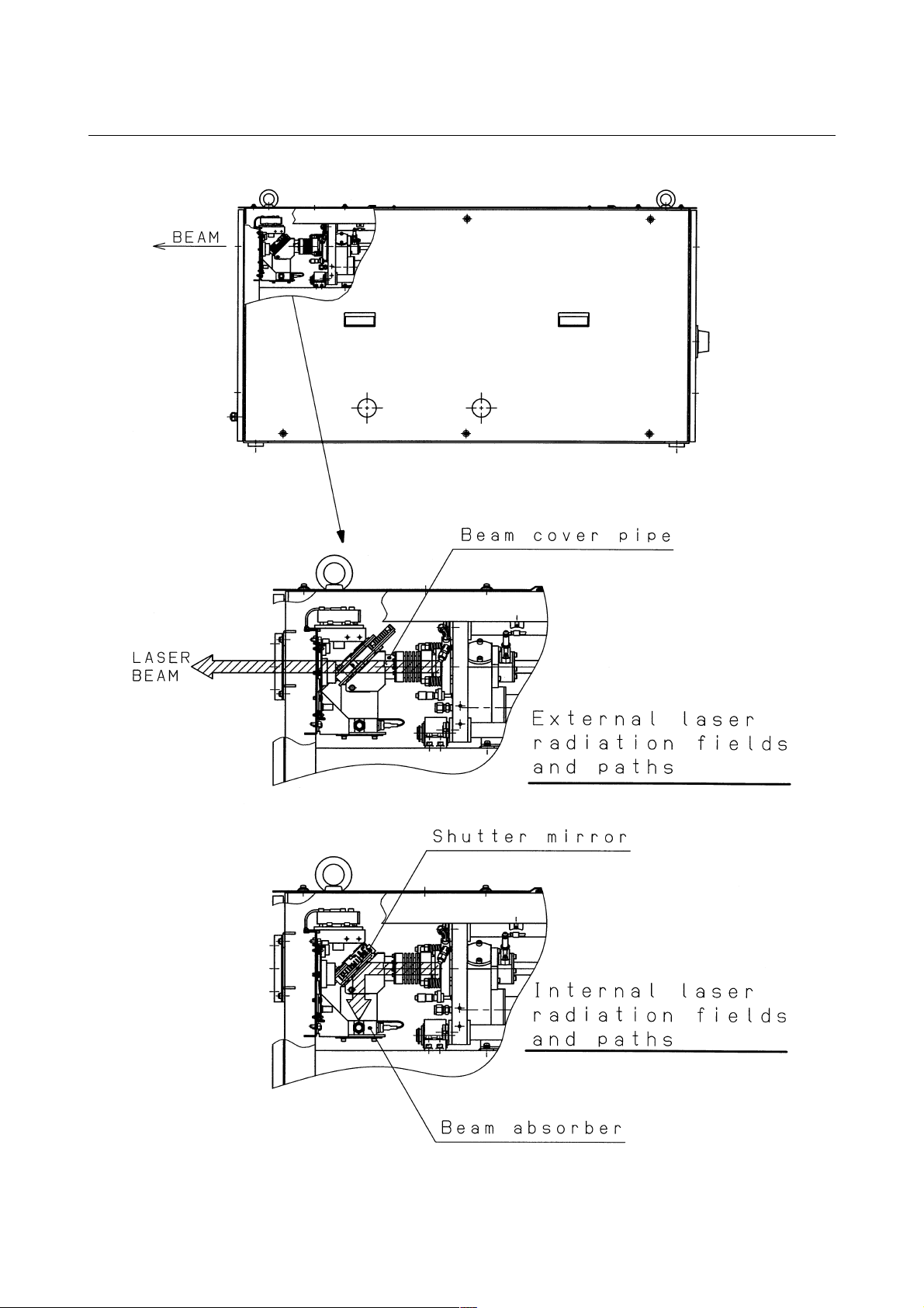
3) Position of laser beam emission
Fig.2.1(a) is the position of panel that laser beam exposure is
occurred without panel in C1000-E, when your maintenance.
Fig.2.1(b) is the position of panel that laser beam exposure is
occurred without panel in C2000-E, when your maintenance.
Fig.2.1(c) is the position of panel that laser beam exposure is
occurred without panel in C4000-E, when your maintenance.
Fig.2.1(d) is the position of laser beam delivery in C1000-E.
Fig.2.1(e) is the position of laser beam delivery in C2000-E.
Fig.2.1(f) is the position of laser beam delivery in C4000-E.
- 8 -

B-70315EN/01 2.SAFETY
Fig.2.1(a) Laser beam exposure position without panel as operating (C1000-E)
Fig.2.1(b) Laser beam exposure position without panel as operating (C2000-E)
Fig.2.1(c) Laser beam exposure position without panel as operating (C4000-E)
- 9 -
2.SAFETY B-70315EN/01
Fig.2.1(d) The position of laser beam delivery (C1000-E)
- 10 -
B-70315EN/01 2.SAFETY
Fig.2.1(e) The position of laser beam delivery (C2000-E)
Fig.2.1(f) The position of laser beam delivery (C4000-E)
- 11 -

2.SAFETY B-70315EN/01
2.2 HIGH VOLTAGE
1) Potential hazards
There is RF voltage of 3 to 4kVo-p in the cabinet of the laser
oscillator.
There is 200 VAC power in the relay panel, be careful not to
touch the high voltage.
2) Safety recommendations
When it checks the oscillator and exchange the unit, intercept a
main breaker of the oscillator and the power supply. Lock the
breaker to prevent misconnection and display the sign while
working.
Install safety cover after unit replacement or cable connection.
Unless safety cover is installed, never perform operation.
Follow standard industrial safety practices for working with high
voltage.
EXAMPLES
• Do not work on the laser oscillator if you are tired or have
taken medicine.
• Do not wear anything metal, like a ring, bracelet, watch,
belt buckle, earrings, or keys.
• They might contact high voltage.
• Never stand on a wet surface.
• Do not touch electrical components in the cabinets with
both hands at once. Keep one hand in a pocket.
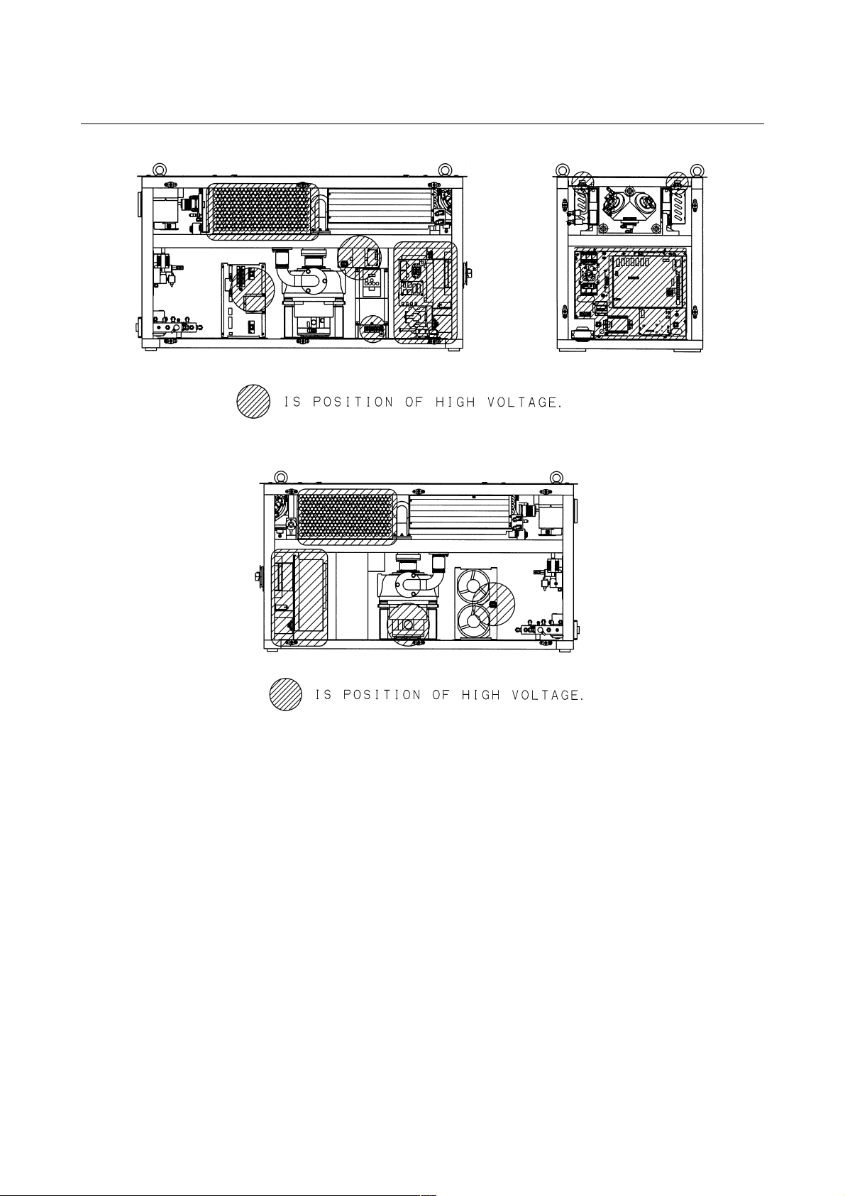
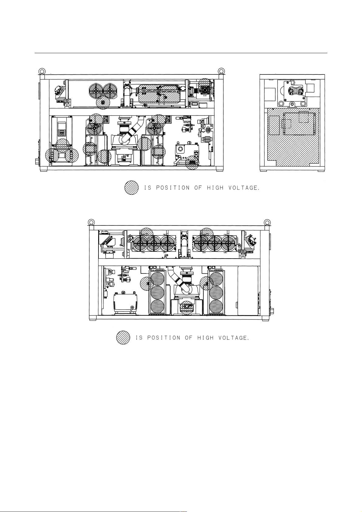
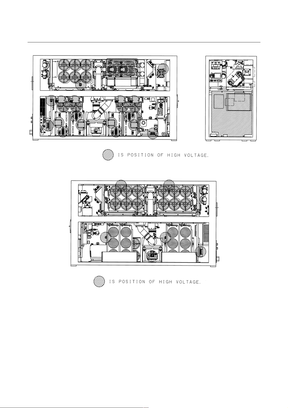
3) Position of high voltage
Fig.2.2(a) is the position of high voltage in C1000-E (Front,
maintenance side).
Fig.2.2(b)is the position of high voltage in C1000-E (Back side).
Fig.2.2(c) is the position of high voltage in C2000-E (Front,
maintenance side).
Fig.2.2(d)is the position of high voltage in C2000-E (Back side).
Fig.2.2(e) is the position of high voltage in C4000-E (Front,
maintenance side).
Fig.2.2(f) is the position of high voltage in C4000-E (Back side).
- 12 -
B-70315EN/01 2.SAFETY
Fig.2.2(a) Position of high voltage in C1000-E (Front, maintenance side)
Fig.2.2(b) Position of high voltage in C1000-E (Back side)
- 13 -
2.SAFETY B-70315EN/01
Fig.2.2(c) Position of high voltage in C2000-E (Front, maintenance side)
Fig.2.2(d) Position of high voltage in C2000-E (Back side)
- 14 -
B-70315EN/01 2.SAFETY
Fig.2.2(e) Position of high voltage in C4000-E (Front, maintenance side)
Fig.2.2(f) Position of high voltage in C4000-E (Back side)
- 15 -

2.SAFETY B-70315EN/01
2.3 SAFETY ENCLOSURE (AT YOUR WORK STATION)
1) Potential hazards
CO
beam is delivery from oscillator. Direct or scattered beam is
2
exposed.
2) Safety recommendations
Mount the safety enclosure made of acrylic resin which can
absorb the laser beam around the working environment.
Mount the interlock switch on the safety enclosure door which
extinguishes the laser beam output when the door is open. Never
perform operation without safety cover of laser machine.
- 16 -

B-70315EN/01 2.SAFETY
2.4 FIRE
1) Potential hazards
When you work with the laser oscillator or machine, hot
fragments or slag can scatter from your workpiece. The CO
beam or a reflection of it could ignite flammable material.
2) Safety recommendations
The direct or scattered laser beam can ignite flammable materials
such as paper, cloth, and wood. Provide a beam absorber behind
the workpiece and around it during maintenance. The absorber
can be anodized aluminum, graphite or brick.Put a shield
between yourself and the workpiece when the CO
Even diffuse reflections can harm eyes and skin and may ignite
flammable material.
beam is on.
2
2
- 17 -

2.SAFETY B-70315EN/01
2.5 TOXIC FUME
1) Potential hazards
Some materials such as certain plastics can emit toxic fume
when they burn under the laser beam.
2) Safety recommendations
Install the exhaust system to remove toxic fume from the work
environment.
Consult the manufacturer of the material you are processing to
learn if it creates any fumes when heated or burned.
- 18 -

B-70315EN/01 2.SAFETY
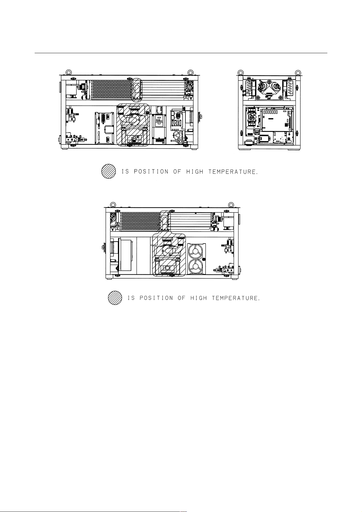
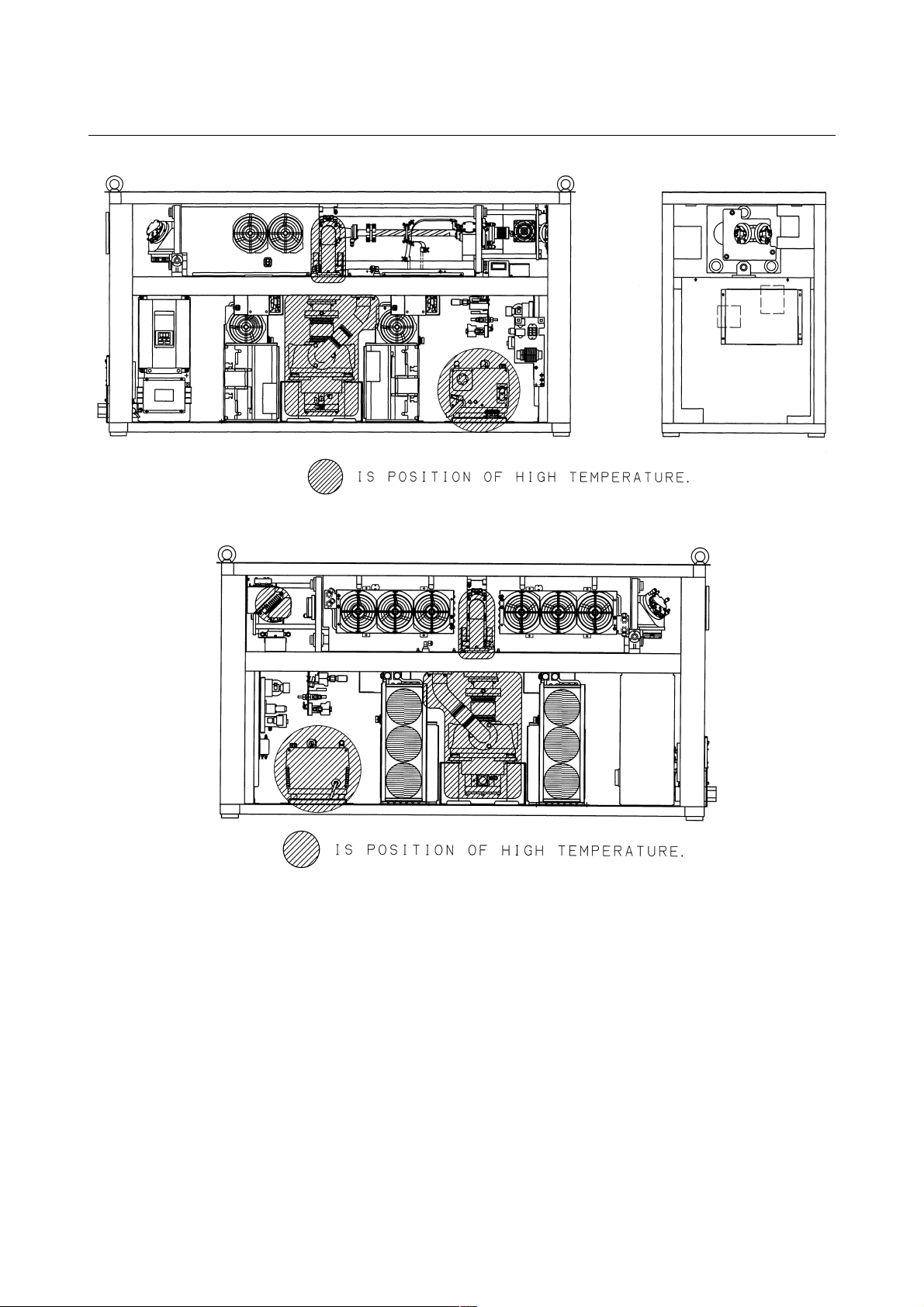
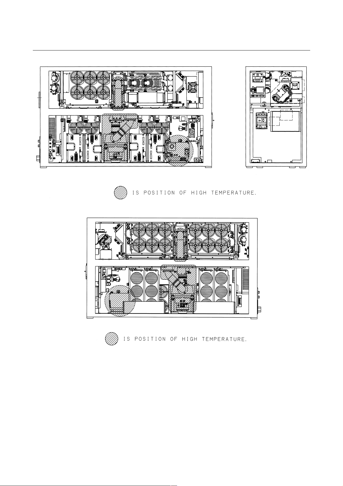
2.6 HIGH TEMPERATURE
1) Potential hazards
When you touch a part of high temperature, your skin burn.
2) Safety recommendations
The pipes of the gas circular system are very a high temperature.
Do not touch pipes, heat exchanger and turbo blower because it
does not do the burn. It is hot immediately after having stopped
driving. After getting cold enough in case of removing, dismount
it.
3) Position of high temperature
Fig.2.6(a) is the position of high temperature in C1000-E (Front,
maintenance side).
Fig.2.6(b) is the position of high temperature in C1000-E (Back
side).
Fig.2.6(c) is the position of high temperature in C2000-E (Front,
maintenance side).
Fig.2.6(d) is the position of high temperature in C2000-E (Back
side).
Fig.2.6(e) is the position of high temperature in C4000-E (Front,
maintenance side).
Fig.2.6(f) is the position of high temperature in C4000-E (Back
side).
- 19 -
2.SAFETY B-70315EN/01
Fig.2.6(a) Position of high temperature in C1000-E (Front, maintenance side).
Fig.2.6(b) Position of high temperature in C1000-E (Back side).
- 20 -
B-70315EN/01 2.SAFETY
Fig.2.6(c) Position of high temperature in C2000-E (Front, maintenance side).
Fig.2.6(d) Position of high temperature in C2000-E (Back side).
- 21 -
2.SAFETY B-70315EN/01
Fig.2.6(e) Position of high temperature in C4000-E (Front, maintenance side).
Fig.2.6(f) Position of high temperature in C4000-E (Back side).
- 22 -

B-70315EN/01 2.SAFETY
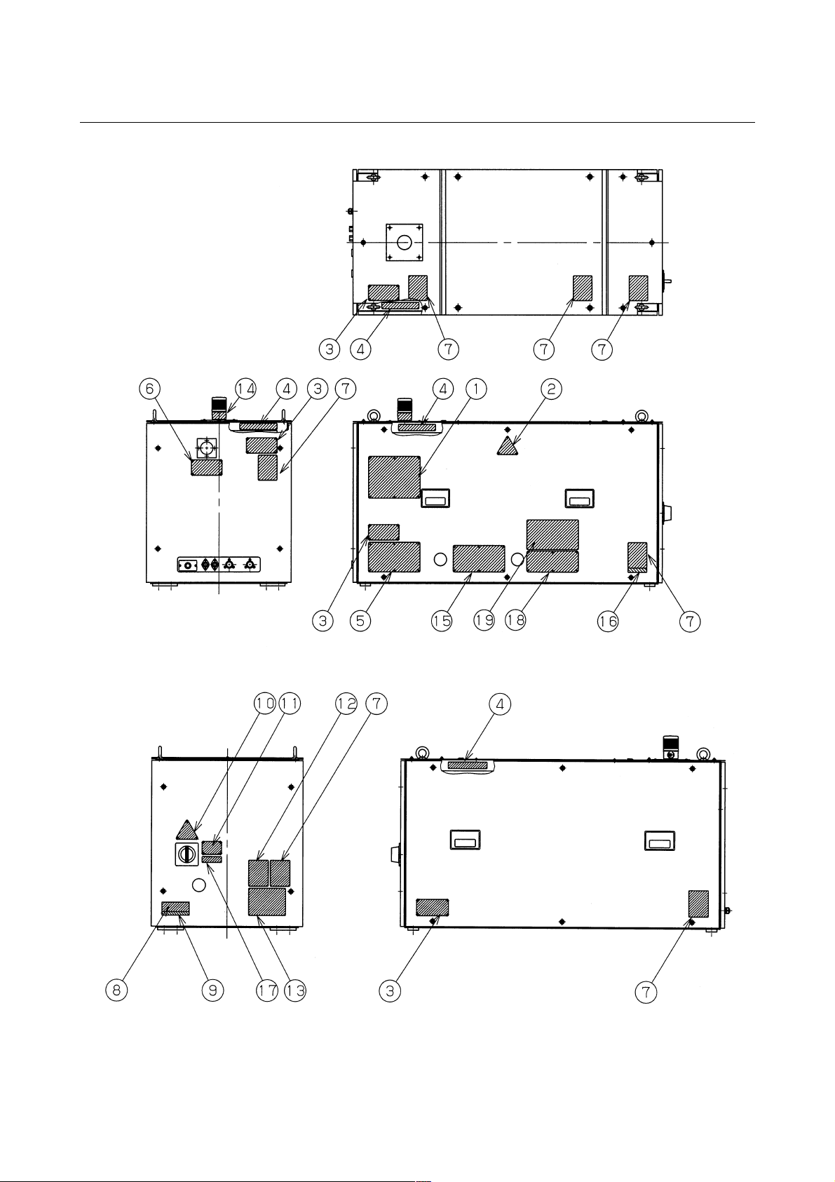
2.7 WARNING LABELS
Fig.2.7(a)-(f) show the location of the warning labels indicating the
high voltage and laser beam path.
Fig.2.7(a) is the location of the warning sticker (C1000-E:Front side).
Fig.2.7(b) is the location of the warning sticker (C1000-E:Back side).
Fig.2.7(c) is the location of the warning sticker (C2000-E:Front side).
Fig.2.7(d) is the location of the warning sticker (C2000-E:Back side).
Fig.2.7(e) is the location of the warning sticker (C4000-E:Front side).
Fig.2.7(f) is the location of the warning sticker (C4000-E:Back side).
- 23 -
2.SAFETY B-70315EN/01
Fig.2.7(a) Location of the warning sticker (C1000-E:Front side).
Fig.2.7(b) Location of the warning sticker (C2000-E:Back side).
- 24 -

B-70315EN/01 2.SAFETY
Fig.2.7(c) Location of the warning sticker (C2000-E:Front side).
Fig.2.7(d) Location of the warning sticker (C2000-E:Back side).
- 25 -

2.SAFETY B-70315EN/01
Fig.2.7(e) Location of the warning sticker (C4000-E:Front side).
Fig.2.7(f) Location of the warning sticker (C4000-E:Back side).
- 26 -

B-70315EN/01 2.SAFETY
Detail of warning sticker
(1) Warning logotype (C1000-E)
(1) Warning logotype (C2000-E, C4000-E)
- 27 -

2.SAFETY B-70315EN/01
(2) Warning logotype
(3) Label for defeasible non-interlocked protective housing
(4) Label for defeasible non-interlocked protective housing
(5) Caution label for lifting
- 28 -

B-70315EN/01 2.SAFETY
(6) Aperture label
(7) Label of non-interlocked protective panel
(8) Identification label
- 29 -

2.SAFETY B-70315EN/01
(9) Address label
(10) High voltage warning label
(11) Supply voltage label
(12) Label of over-current protective
- 30 -

B-70315EN/01 2.SAFETY
(13) Label of motor and transformer (C1000-E)
(13) Label of motor and transformer (C2000-E)
(13) Label of motor and transformer (C4000-E)
- 31 -

2.SAFETY B-70315EN/01
(14) Label of warning light
(15) Maintenance label
(16) Certification label
(17) Short-circuit interrupting capacity of main breaker (C1000-E)
(17) Short-circuit interrupting capacity of main breaker (C2000-E,
C4000-E)
- 32 -

B-70315EN/01 2.SAFETY
(18) Label for regurating the atmospheric gases in the oscillator
housing
(19) Label for cooling water and laser gas
- 33 -

2.SAFETY B-70315EN/01
2.8 HIGH-PRESSURE GAS
Do not allow any dangerous or high-pressure gas to get into the
oscillator housing. The oscillator cabinet has a hermetic structure
(dustproof and dripproof), it cannot be ventilated easily.
Flammable gases such as oxygen can cause a fire or explosion.
Toxic gases can harm operators during maintenance. Organic gases
can degrade machining performance. High-pressure gases can damage
a panel or the cabinet, resulting in injury from flying matters.
If such a gas accidentally gets into the oscillator housing, remove a
panel for ventilation. The installation room must be also well
ventilated.
To purge the oscillator housing, use purified, low-pressure air or
nitrogen.
- 34 -

B-70315EN/01 2.SAFETY
2.9 KEY CONTROL
All the laser products have to comply with the various kinds of laser
safety regulations, which include the use of key control. For instance,
FDA PART 1040 PERFORMANCE STANDARDS FOR LIGHTEMITTING PRODUCTS, Sec 1040. 10 (f), (4) states: "Each laser
system classified as a Class IIIb or IV laser product shall incorporate a
key-actuated master control. The key shall be removable and the laser
shall not be operable when the key is removed" and EN60825-1:1994,
4.5 Key control state "Any laser system belonging to one of the
following classes shall incorporate a key operation master control:
Class 4 and Class 3B, except for Class 3B with not more than five
times the AEL of Class 2 in the wavelength range from 400 nm to 700
nm. The key shall be removable and the laser radiation shall not be
accessible when the key is removed."
Because the laser package products offered by FANUC cannot
produce the laser beam as they are in the state of shipment, the system
integrator who incorporates FANUC products into the system, which
generates the laser beam, is obliged to incorporate the master key as
defined by the relevant regulation.
- 35 -

2.SAFETY B-70315EN/01
2.10 SHUTTER LOCK
The shutter lock is prepared because it dose not put out the laser beam
by mistake. If you do not put out the beam, lock the shutter.
Use the mechanical switch at shutter lock switch, not electrical
component (Relay)or switching circuit (Transistor, FET).
Use the one with the compulsion dissociation mechanism for the
switch used for the shutter lock circuit and the switch for welding
prevention.
To designer of laser processing machine
1 Use a mechanical switch for the switch used to lock
the shutter. Do not use an electric switch (For
instance, transistor circuit, etc.). Moreover, use the
one with the contact dissociation mechanism to
prevent welding for a mechanical switch.
2 Put it in the series of the contact of the emergency
stop button in the shutter lock circuit. When the
emergency stop switch is pushed, it is necessary to
intercept the power supply to the shutter.
- 36 -

B-70315EN/01 2.SAFETY
2.11 EMERGENCY STOP BUTTON
Press the emergency stop button when it is dangerous and breaks
down. The oscillator is stopped discharging, gas pressure control and
stand by purge state.
Use the one with the compulsion dissociation mechanism for the relay
used for the emergency stop circuit and the switch for welding
prevention.
- 37 -

2.SAFETY B-70315EN/01
2.12 WARNING LIGHT (OPTIONAL)
Laser oscillator is equipped with the warning light optionally. The
light is flashed during discharging and ready of laser beam emission.
Be careful of laser beam and high voltage.
To designer of laser processing machine
In EN60825-1, it needs the design with the fail safe
or redundant for warning equipment. The redundant
warning light is needed near the work-point of
processing machine. The warning light is prepared
for the oscillator. Select this as a warning light more
than the second for the fail safe.
- 38 -

B-70315EN/01 3.INTERNAL STRUCTURE
3 INTERNAL STRUCTURE
- 39 -

3.INTERNAL STRUCTURE B-70315EN/01
3.1 GENERAL
Figs.3.1(a) to (c) show the block diagram of the laser oscillator.
The FANUC LASER C1000/C2000/C4000-MODEL E consists of a
laser resonator, laser excitation power supply, forced gas circulating
system, pressure controller, exhaust controller, CNC interface, and a
protective housing.
Fig.3.1(a) Block diagram (C1000-E)
- 40 -

B-70315EN/01 3.INTERNAL STRUCTURE
Fig.3.1(b) Block diagram (C2000-E)
- 41 -

3.INTERNAL STRUCTURE B-70315EN/01
Fig.3.1(c) Block diagram (C4000-E)
(1) Laser resonator
The laser resonator consists of several discharge tubes,
connected in series using folding mirrors, with a rear mirror and
output mirror placed at the open ends of the discharge tubes, thus
sealing the tubes. The resonator is fitted with a gas pipe
connecting port through which laser gas is fed into the discharge
tubes.
A discharge from the electrodes of the discharge tube energizes
CO
molecules, which emit light. This light is amplified by
2
stimulated emission, repeated between the rear mirror and output
mirror, a laser beam being emitted from the output mirror.
(2) Laser excitation power supply
This is a 2 MHz high-frequency power supply, the output of
which is controlled by the CNC. This power supply is used to
create a discharge in the laser gas flowing through the discharge
tubes, thus energizing CO
molecules.
2
- 42 -

B-70315EN/01 3.INTERNAL STRUCTURE
(3) Forced gas circulating system
A gas circulating system is configured by connecting the
resonator and turbo blower with a circulating pipe. Laser gas is
forced through the discharge tubes at a speed of 200 m/s or
higher.
A water-cooled heat exchanger, used to cool the hightemperature gas from the discharge tubes, is provided at the inlet
side of the turbo blower. At the outlet side of the turbo blower,
another water-cooled heat exchanger dissipates the compression
heat.
(4) Pressure control unit
The laser gas pressure within the forced gas circulating system is
controlled by commands issued from the CNC, thus ensuring
stable laser output.
(5) Exhaust control unit
The laser gas flow is controlled by commands issued from the
CNC.
(6) CNC interface
Interface used to connect a FANUC Series 16i-L. CNC
commands that, control the operation of the laser oscillator, such
as start/stop and laser output, are input via this interface.
(7) Protective housing
An enclosure that houses the above components. The housing,
consisting of metal panels and doors, completely encloses the
laser oscillator, thus protecting the operator from exposure to
laser radiation and from high voltages. All panels are screwfixed and cannot be removed without an appropriate tool.
The doors are also designed to prevent an accident from
occurring as a result of careless operation. The doors can be
opened only when the main circuit breaker is open. A door
interlock function is also supported.
- 43 -

3.INTERNAL STRUCTURE B-70315EN/01
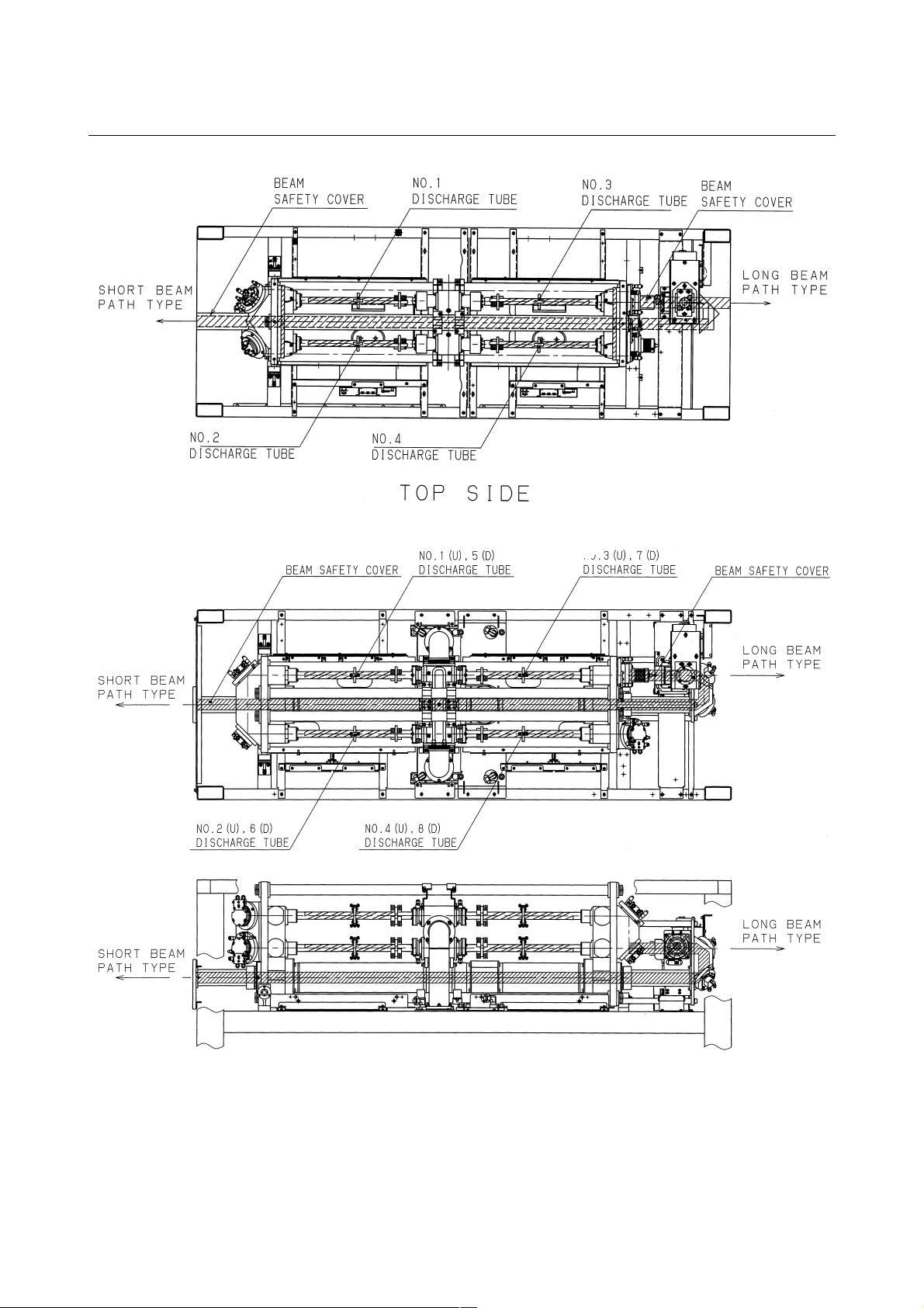
3.2 COMPONENT DETAILS
The following describes the details of each component of the laser
oscillator. Figs.3.2(a) to (f) show the internal structure.
Fig.4.2(a) Internal structure of C1000-E (Front, maintenance side)
Fig.4.2(b) Internal structure of C1000-E (Back side)
- 44 -

B-70315EN/01 3.INTERNAL STRUCTURE
Fig.4.2(c) Internal structure of C2000-E (Front, maintenance side)
Fig.4.2(d) Internal structure of C2000-E (Back side)
- 45 -

3.INTERNAL STRUCTURE B-70315EN/01
Fig.4.2(e) Internal structure of C4000-E (Front, maintenance side)
Fig.4.2(f) Internal structure of C4000-E (Back side)
- 46 -

B-70315EN/01 3.INTERNAL STRUCTURE
(1) Resonator
The resonator consists of an output coupler, rear mirror, folding
mirrors, discharge tubes, power sensor unit, etc. It converts
electrical energy first to laser gas, then to optical energy (10.6mm single-wavelength laser beam).
(2) Output coupler
A transmitting/reflecting mirror which outputs the laser beam
after it has been amplified. The output coupler consists of a ZnSe
(zinc selenide) substrate, coated with dielectric. ZnSe is tightly
toxic. Be particularly careful, therefore, when handling the
output coupler.
(3) Rear mirror
A reflecting mirror consisting of a Ge (germanium) substrate,
coated with dielectric. Having a high reflectance of 99.5%, the
rear mirror is used to reflect the laser beam within the resonator
while transmitting 0.5% of the laser light so that the beam can be
monitored externally.
(4) Folding mirror
The folding mirror, consisting of a 45° block and a gold-coated
Si (silicon) substrate, is used to divert the laser beam through
90°. It also linearly polarizes the laser beam.
(5) Discharge tube
A pair of Ag (silver) electrodes are metallized on the surface of a
hollow quartz glass pipe. A high-frequency discharge between
these electrodes injects electrical energy into the laser gas.
Each electrode is coated with ceramic, preventing it from
degrading and thus improving system reliability.
(6) Trigger electrode
A predischarge placed outside the laser oscillation area can
facilitate the start of the main discharge. With it, the laser output
is completely zero when the beam is off.
(7) Power sensor
An optical sensor which detects the intensity of the laser beam,
transmitted through the rear mirror, thus enabling monitoring of
the laser output level.
(8) Gas circulating system
A gas circulating path including a turbo blower, heat exchangers,
and circulating pipes, which supplies and exhausts laser gas to
and from the discharge tubes at high speed.
- 47 -

3.INTERNAL STRUCTURE B-70315EN/01
(9) Turbo blower
During laser oscillation, the laser gas pressure is 100 to 700
(1330 to 9310 Pa) when DGN. The turbo blower circulates this
rough-vacuum gas at high speed (up to 200 m/s within the
discharge tubes) without contaminating the gas.
(10) Heat exchanger (inlet)
Heat exchanger used to cool the laser gas that has been heated by
discharge, before it is drawn into the turbo blower.
(11) Heat exchanger (outlet)
Heat exchanger used to cool the laser gas that has been heated by
compression in the turbo blower, before being forced into the
discharge tubes.
(12) Gas controller (C1000-E)
The gas controller always monitors the gas pressure in each
discharge tube and supplies the fresh laser gas to the circulating
system to keep the pressure constant. It also monitors the supply
status of the laser gas, purge check for the circulating system,
and other items and has a function of adjusting the amount of
flow of the gas to be exhausted.
(13) Pressure controller (C2000-E, C4000-E)
This unit constantly monitors the gas pressure in the discharge
tubes and supplies fresh laser gas to the gas circulating system,
thus maintaining a constant pressure in the discharge tubes.
This unit also monitors the laser gas supply state and the purging
state in the gas circulating system.
(14) Exhaust pump unit
This unit is used to vacuum-exhaust laser gas from the gas
circulating system such that its pressure falls to that used for
laser oscillation. Also, within this unit, a small amount of
circulating gas is constantly being exchanged, to prevent
degradation of the circulating gas. For the C1000-E, the exhaust
pump is installed separately.
(15) Exhaust controller (C2000-E, C4000-E)
The exhaust controller controls the flow rate of the laser gas
exhausted by the exhaust pump unit. It adjusts the gas flow rate
from that used for gas exchange to that used for pressure control.
In the event of a power failure, the exhaust controller
immediately returns the exhaust pump unit to atmospheric
pressure, thus protecting the pump.
(16) Hour meter
The hour meter indicates the total number of hours that the laser
oscillator has operated (how many hours the exhaust pump has
operated), to indicate whether maintenance or inspection is
necessary.
- 48 -

B-70315EN/01 3.INTERNAL STRUCTURE
(17) Shutter
The shutter consists of a gold-coated reflecting mirror, mounted
on the rotating arm of a rotary solenoid. The shutter can be
opened and closed instantaneously by issuing a CNC command.
For safety, the shutter is equipped with a temperature sensor
which allows the system to monitor the temperature of the
shutter.
(18) Beam absorber
While the laser oscillator is operating with the shutter closed, the
laser beam is guided into the beam absorber. The beam absorber
absorbs nearly 100% of laser beam and is water-cooled, allowing
it to safely absorb the beam for relatively long periods. For
safety, the beam absorber is equipped with a temperature sensor
which allows the system to monitor the temperature of the beam
absorber.
(19) Water distributor
This unit distributes cooling water, supplied from either a chiller
unit or a temperature-regulated external water supply, to each
unit in the laser oscillator. For safety, the water distribution unit
is equipped with a flow sensor which allows the system to
monitor the flow rate of the
(20) Laser power supply unit
This unit rectifies and smoothes the 3-phase 200/220-VAC input,
then supplies DC power to the RF inverter by controlling the
PWM DC-DC converter, as directed by commands received
from the CNC.
The RF inverter converts DC power to 3 to 4 kVP
frequency (2 MHz) power, then outputs it to the matching box.
(21) Matching box
The matching box contains a matching circuit, consisting of coils
and capacitors, which ensures that power is effectively input to
the discharge tubes. The matching box is connected to the laser
power supply unit via either a high-voltage cable or coaxial
cable.
(22) Beam folding unit (C2000-E, C4000-E)
This unit reverses the direction of the laser beam in the oscillator.
Two zero-shift mirrors are used to ensure that the polarization of
the light remains constant. The C4000-E (short optical path type)
employs a circular polarization mirror as upper one, such that a
circularly polarized beam is produced.
(23) Intermediate PCB B
This PCB transmits signals output by the shutter section, such as
those from the limit switch, absorber temperature sensor, power
sensor, and condensation sensor, to the interface PCB.
O-P
high-
- 49 -

3.INTERNAL STRUCTURE B-70315EN/01
(24) Input unit
The input unit consists of an interface PCB, stabilized power
supply, and power magnetics cabinet. It transfers signals
between the laser oscillator and CNC, and supply power to each
unit.
(25) Interface PCB
I/O LINK (serial interface). Because this is a serial interface,
optical fiber cable can be used to enable long-distance
transmission.
(26) Stabilized power supply
This unit converts the 200/220 VAC power source to DC power
for the interface PCB and other units.
(27) Input unit (Control PCB)
This PCB sends the contractor open/close signal to the power
magnetics cabinet, as directed by commands received from the
CNC. It also notifies the CNC of the open/close status of the
circuit breaker in the power magnetics cabinet.
(28) Condensation sensor unit
This unit is mounted on the output mirror holder. If the sensor
detects that the amount of dew has exceeded the maximum
allowable level, an alarm (abnormal water temperature) is issued
and laser output is stopped, thus preventing a fault from
occurring.
(29) Inverter
This inverter drives the turbo blower. It is responsible for
acceleration/deceleration control during start and stop of the
blower.
(30) Guide laser (laser diode unit)
A CO
laser beam is invisible to the naked eyes. The
2
semiconductor light source, therefore, is provided to enable
checking of the laser beam optical axis by superimposing a
visible semiconductor laser beam on the same optical axis.
The operation of this light source is linked to the mechanical
shutter. The semiconductor laser beam is output only while the
shutter is closed. Using this beam, the optical axis of the external
optical system can be adjusted roughly and a reference position
for the machining point determined.
(31) Turbo PCB
This PCB relays signals between the turbo blower and inverter,
interface PCB.
- 50 -

B-70315EN/01 3.INTERNAL STRUCTURE
(32) Safety box
This is consisted of relay and indicator for interlock circuit.
(Run ON, HV ON, Shutter open)
- 51 -

4.INSTALLATION B-70315EN/01
4 INSTALLATION
- 52 -

B-70315EN/01 4.INSTALLATION
4.1 INSTALLATION PROCEDURE
Use the following procedure to make adjustments and checks during
installation.
(1) Check the environment at the installation location.
• Environmental conditions
1) Ambient temperature : +5° C to +30°C
2) Temperature variation : 1.1°C/minute maximum
3) Humidity : 75% or below (relative humidity)
4) Vibration : Acceleration not to exceed 0.05G.
Vibration amplitude not to exceed 5mm.
5) Atmosphere : Dust must be minimized. There must
be no organic volatile components.
6) Laser gas : Composition
CO
He : 40±2.0%
N
H
C
Purity : 99.99% or more
:5±0.25%
2
:55±2.75%
2
O : 5 ppm or less
2
: 1 ppm or less
mHn
(2) Remove all clamps.
The clamps are used only in transit. In particular, loosen the
resonator clamp before it is stored. If the resonator is left for a
long time with the clamp tightened, the resonator is likely to be
deformed. The clamp locations are shown in Fig. 4.1 (a) to Fig.
4.1 (c).
- 53 -

4.INSTALLATION B-70315EN/01
Fig.4.1(a) Clamp layout (C1000-E)
- 54 -

B-70315EN/01 4.INSTALLATION
Fig.4.1(b) Clamp layout (C2000-E)
- 55 -

4.INSTALLATION B-70315EN/01
Fig.4.1(c) Clamp layout (C4000-E)
- 56 -

B-70315EN/01 4.INSTALLATION
(3) Check the units installed in the main unit cabinet.
• Check items
1) Check whether any printed circuit boards are loose or
removed.
2) Check whether any cables are damaged (such as
damaged sheathing).
3) Check whether any connectors are loose or detached.
4) Check that the discharge tubes are neither cracked nor
damaged.
5) Check that the turbo blowers, exhaust pump, and other
units are neither loose nor missing.
6) Check that the power supply units and matching boxes
are neither loose nor missing.
7) Check that the input unit is neither loose nor missing.
8) Check that the connection to the electrode (copper
plate) of each discharge tube is not loose.
9) Check that the water and gas pipes are not loose.
(4) Check all screw terminals in the units.
• Check items
1) Terminal block of the input unit
2) Power supply units and matching boxes
(5) Check the oil level in the turbo blowers and exhaust pump, and
check for oil contamination.
For details of how to supply and replace the oil, see Section 5.3.
(6) Connect the power and signal lines to the oscillator.
See Section 4.4.3 for details.
• Check items
1) Cable between the CNC and oscillator
To connect this cable, apply the procedure described
in the "FANUC Series 16i-L Connection Manual."
2) Oscillator power cable
3) Grounding cable (< 10Ω)
4) Inter-unit connection between the oscillator and
exhaust pump (C1000-E)
(7) Check all printed circuit board settings.
• Check items
1) Setting pins on the oscillator IF PCB
See Section 6.5.5 for an explanation of the setting pins
on the IF PCB.
(8) Laser gas and cooling water pipes.
See Section 4.4.1 and Section 4.4.2 for details.
• Check items
1) Laser gas pipe material
Recommended gas pipe
Nylon tube AS1, manufactured by Junko Co. Ltd.
Polyfrotube, manufactured by Imperial Co. Ltd.
- 57 -

4.INSTALLATION B-70315EN/01
2) Gas leakage from external piping
3) Laser gas composition and purity (See Section
4.4.1.2.)
4) Quality of cooling water (See Section 4.4.1.1.)
5) Flow of cooling water (IN, OUT)
6) Exhaust pump connection (See Subsec.4.4.4.)
(9) Check the input power supply voltage, frequency and phase
sequence.
• Check items
1) 200/220 VAC +10%, -15%, 50/60 Hz ±1 Hz, 3-phase.
Note, however, that the combination of 220 V and 50
Hz is not supported.
2) Input power supply rating
3) Direction of phase rotation
(10) Turn on the power, then check the operation of the fan motors in
the housing.
The fan motors installed in the housing of the oscillator start as
soon as the power to the CNC is turned on. Check the operation
of each fan motor. Note, however, that the fan motor installed in
the laser power supply does not start until the oscillator sequence
reaches the turbo blower ON operation.
(11) Check the parameters and setting data.
Check the parameters against the data sheets attached to the
oscillator. If a value other than those given on the data sheets is
set, correct the setting. Note, however, that parameter No. 15270
and parameter No. 15204 are set automatically, so that these
parameters need not be modified.
CAUTION
Each oscillator has unique parameters. Check the
setting data according to the attached data sheets.
Be particularly careful to store these data sheets
safely.
(12) Check that cooling water is supplied normally, and that there is
no water leakage inside the oscillator or at any external
connection points.
• Check items
1) Turn off the main circuit breaker of the oscillator and
power supply.
2) Check that the water inlet (IN) and outlet (OUT) of the
oscillator are connected correctly. If the connections
are reversed, the flow sensor installed at the outlet will
not function. When a valve is attached to the
distributor unit (C4000-E : see Fig. 4.2.2), check that
the valve is open.
3) Fully open the valves on the exhaust side so that the
flow of water is not impeded. By manually operating
- 58 -

B-70315EN/01 4.INSTALLATION
the chiller unit, pass cooling water through the system
at a flow rate of about 10liters/minute. Then, check
that there is no water leakage at the following
locations:
1. The water inlet (IN) and outlet (OUT) of the
oscillator
2. The water piping (including all tubes and joints)
in the oscillator
4) Provided no water leakage is observed in step 3) above,
allow cooling water to flow through the oscillator at
the specified flow rate. Set the output pressure of the
cooling water circulating unit to 0.5 MPa. Then, check
that there is no water leakage at the following
locations:
1. The water inlet (IN) and outlet (OUT) of the
oscillator
2. The water piping (including tubes and joints) in
the oscillator
5) Stop the chiller unit, then switch the operation mode
from manual (local) mode to automatic (remote)
mode.
6) Provided no water leakage is observed, start the
oscillator, then set the RUN key to ON. Check that the
cooling water circulating unit can be operated
according to commands issued from the CNC. At this
time, check whether the cooling water is flowing at the
specified flow rate through each pipe in the oscillator.
If the flow rate is less than the specified value, alarm
No. 4072 (low cooling water flow rate) is issued soon
after the chiller unit is started. If this alarm is issued,
proceed as indicated in the guidance corresponding to
this alarm.
7) Check that the temperature of the cooling water is set
to room temperature plus 1°C. (The temperature of the
cooling water may be set to about 27°C throughout the
year.) The highest temperature that may be set is 30°C.
(13) Conduct an oscillator vacuum leakage test.
1) Check the oscillator for any internal leakage.
The procedure for performing a leakage check is given in
Section 4.3 (3).
2) When first starting the oscillator, check that gas is output
from the gas outlet of the oscillator. Depending on the
parameter settings, it may take as long as one minute before
gas is output.
If no gas is output, the exhaust pump rotation may be
reversed. If this situation is left uncorrected, the exhaust
pump may ultimately start to make an abnormal sound, and
the thermal switch may trip. In the worst case, the gas
circulating system may be contaminated with exhaust pump
oil.
- 59 -

4.INSTALLATION B-70315EN/01
(14) Check that the laser gas pressure is controlled normally.
1) Set all bits of parameter No. 15025 through parameter No.
15028 to 0 because only the pressure control operation is to
be checked, without causing discharge. Set parameter No.
15240 to the standard value 10, then check the pressure
control status of the laser oscillator. Turn on RUN (pressure
control signal), then check the pressure control status
against the following parameters, while referring to DGN
905:
1. Parameter No. 15241 for discharge start state
2. Parameter No. 15242 for base discharge state
If the pressure control status is abnormal, alarm No. 4073,
No. 4081, or No. 4078 is issued. Proceed as indicated in the
guidance corresponding to this alarm. Check also that the
laser gas flow rate in the base discharge state satisfies the
specified value.
2) If the laser gas flow rate is abnormal, perform adjustment as
described in Sections 9.4.3 and 9.5.
3) Reset the values of the bits of parameter No. 15025 through
parameter No. 15028 to their original values. This
completes the check.
(15) Perform laser oscillation to achieve discharge aging. If the
oscillator is left unused for one week or more, discharge aging is
required. See Section 9.10 for details of discharge aging.
- 60 -

B-70315EN/01 4.INSTALLATION
(16) Check the oscillation characteristics and output. See Section
4.3(1) for details of the check method.
• Check items
1) Oscillation characteristic check :
- Check that the correction coefficient is 1100 or
less.
- Check that the discharge voltage is within the
factory-set value plus 200 V.
If the correction coefficient or discharge voltage
exceeds the maximum, repeat discharge aging.
2) Discharge margin check
- Check that a margin is provided.
3) Voltage margin check
- Check that no alarm is issued.
(17) Check the laser beam mode. For details of the check method, see
Section 4.3 (4).
• Check items
1) Check that there is no significant difference from the
mode specified in the data sheets attached to the
oscillator.
2) Check that the mode shape is perfectly circular.
The beam mode (resonator alignment) may be displaced
due to transportation and storage. In such a case, make an
adjustment according to Section 11.2.1.
(18) Set the hour meter.
Set 50 Hz for those localities where the power supply frequency
is 50 Hz. Set 60 Hz for those localities where the power supply
frequency is 60 Hz.
(19) Optical axis adjustment
To perform optical axis adjustment as part of the installation,
adjust the base table of the oscillator. Never place a heavy object
on the beam outlet plate. Moreover, never make a direct
mechanical connection between this plate and a part on the
mechanical side.
- 61 -

4.INSTALLATION B-70315EN/01
4.2 PREPARATION PRIOR TO SHIPMENT
Prior to shipment and transportation, the packing and checking
operations described below must be performed.
(1) Disconnect all CNC connecting cables.
(2) Disconnect the power cable and ground cable of the input unit in
the main unit cabinet.
(3) Remove the laser gas pipes, and attach blanking plugs to the
pipes to prevent dust from entering.
(4) Remove all cooling water from the oscillator by using
compressed air. For details of how to remove the cooling water,
see Section 4.2.2. Any residual cooling water may result in
corrosion or clogging; furthermore, if any residual cooling water
freezes, a pipe or the oscillator itself may be damaged.
(5) Install all clamps and fit a blanking cap onto the beam outlet.
(6) Check the security of all connectors and printed circuit boards.
Install protective covers.
(7) Check that all removed mounting screws are reinstalled.
(8) Install the cabinet mounting panel and door panel.
- 62 -

B-70315EN/01 4.INSTALLATION
4.2.1 Packing for Transportation
For transportation, the packing requirements described below must be
observed.
FANUC LASER C1000/C2000/C4000-MODEL E
Fig. 4.2.1 Lifiting of oscillator
(1) External dimensions: See the external views.
(2) Weights: 400kg (C1000-E), 700kg (C2000-E), 900kg (C4000-E)
(3) Maximum allowable impact: 2 G
Note that the maximum allowable impact in transit depends
greatly on the means of transport employed, as indicated in
Table 4.2.1.
Table 4.2.1 Maximum allowable impacts according to means of
transport (Units: G)
Means of transport
Airplane Ship Railroad Truck
Direction
Forwards/
backwards
Left/right
Up/down
615125
2.5 12 5 4
2.5 12 5 4
(4) Notes on transportation
When transporting a unit, always observe the notes provided on
the sticker attached to the unit. To lift a unit, run wires or slings
through the four eyebolts, then use a crane to lift the unit.
- 63 -

4.INSTALLATION B-70315EN/01
4.2.2 Removing Cooling Water
Remove cooling water according to the procedure below.
(1) Open the cooling water inlet (IN) and outlet (OUT), and leave
both open. Cooling water will stop draining from the unit after
about 10 minutes.
(2) Once the cooling water has stopped draining, connect a
compressed air hose to the cooling water inlet (IN). Check that
the cooling water outlet is open. Gradually supply compressed
air, allowing the pressure to build up to 0.1 to 0.2 MPa. Never
apply full pressure suddenly.
(3) Continue to supply compressed air at this pressure for about 5
minutes. Increase the compressed air pressure to 0.3 to 0.4 MPa,
and supply air until water inside the white water piping of the
oscillator is completely removed.
(4) When water is no longer output, set the compressed air pressure
to 0. When a drain valve is attached to the distributor unit
(C4000-E: Fig. 4.2.2), open the valve, and supply air according
to the same procedure as (2) and (3). When water is no longer
output, set the compressed air pressure to 0, then close the valve.
Fig 4.2.2 Detail of Distributor (C4000A)
- 64 -

B-70315EN/01 4.INSTALLATION
(5) Next, connect the compressed air hose to the cooling water
outlet (OUT). At this time, ensure that cooling water inlet is
open. Remove water in the same procedure as (2), (3), and (4).
(6) Once all cooling water has been removed, disconnect the
compressed air tube. Then, seal the cooling water inlet (IN) and
outlet (OUT) by attaching the blanking plugs provided with the
oscillator to the PT plugs.
(7) When a valve is attached to the distributor unit (C4000-E), check
that the valve is open. Leave the valve open (for operation,
storage, or transport of the oscillator) except when water is
removed.
CAUTION
Also, the cooling water should be removed from the
oscillator whenever the oscillator is to be stored over
the winter, when there is a danger of the cooling
water freezing. If the cooling water freezes, it may
destroy the cooling water pipes or other cooling
system components.
- 65 -

4.INSTALLATION B-70315EN/01
4.3 DETAILS OF CHECKING
(1) Oscillation characteristics
1) Check that bit 4 of parameter No. 15000 is set to 1.
2) Start the oscillator. When a discharge start switch is
provided, do not set the switch to ON until after LRDY has
been set.
3) The oscillator enters correction mode for three minutes
after start of discharge, and the rated output is automatically
specified. At this time, record the peak output.
4) Record the output, discharge voltage, and current values
two minutes after making the specification. Discharge
voltages (RFV) and currents (RFI) are indicated in DGN
909 through 924, in order from RF No.1 to RF No. 8. When
one power supply unit is used to drive two discharge tubes,
however, the RFV and RFI values for No. 1 through 4 are
the same as those for No. 5 through 8.
5) Record the output values immediately before the elapse of
three minutes after the specification.
6) Upon the termination of three-minute correction mode,
record the correction coefficient (parameter No. 15024).
7) Three minutes after the termination of correction mode,
record the base discharge output, discharge voltage (RFV),
and current (RFI) values.
Compare the measured values of 4) and 7), above, with the
discharge voltage and current characteristics given in the
data sheets. A discharge voltage (RFV) is abnormal if it
exceeds the data sheet value by 200 V or more.
In such a case, check the external laser gas piping and laser
gas composition, or perform aging.
(2) Discharge margin check
1) Modify the parameters listed below.
Bit 4 of parameter No. 15000;
1 → 0 (Correction is not performed.)
Parameter No. 15208:
Setting → 0 (Output feedback is turned off.)
Parameter No. 15209:
Setting → 0 (Output feedback is turned off.)
Parameter No. 15223:
Setting → Setting -60
2) Remove the maintenance panel from the oscillator so that
the discharge tubes can be checked.
3) Start the oscillator. When a discharge start switch is
provided, do not set this switch to ON until after LRDY has
been set. Before discharging, warning message is occurred.
Press the reset key.
4) Check that the discharge tubes do not stop discharging or
trigger discharging for 30 minutes after the start of
discharge.
- 66 -

B-70315EN/01 4.INSTALLATION
5) Upon the completion of the check, restore the parameters
modified in step 1) to their original values.
If discharge stops in step 5) , it indicates a discharge margin
error. Check the external laser gas piping and laser gas
composition, or perform aging.
(3) Power supply margin check (pulse check)
1) Modify the parameters listed below.
Bit 2 of parameter No. 15000:
0 → 1 (Use of assist gas is disabled at beam-on.)
Bit 3 of parameter No. 15000:
0 → 1 (Internal discharge is enabled in manual
mode.)
Bit 0 of parameter No. 15002:
0 → 1 (Internal discharge is enabled in automatic
operation mode.)
Bit 4 of parameter No. 15000:
1 → 0 (Correction is not performed.)
Parameter No. 15208:
→ 0 (Output feedback is turned off.)
Parameter No. 15209:
Setting → 0 (Output feedback is turned off.)
Parameter No. 15210:
1000→ 1100 (C1000-E)
2000→ 2700 (C2000-E)
4000→ 4400 (C4000-E)
2) Start the oscillator. When a discharge start (HV ON)
switch is provided, do not set this switch to ON until after
LRDY has been set.
3) Set the following values on the laser setting screen:
Pc = 1100 W Du = 5% Fr = 5 Hz (C1000-E)
2700 W Du = 5% Fr = 5 Hz (C2000-E)
4400 W Du = 5% Fr = 5 Hz (C4000-E)
4) Perform internal discharge in manual mode.
5) Check that no abnormality occurs for 30 minutes after
beam-on.
6) Upon the completion of the check, restore the parameters
modified in step 1) to their original values.
An alarm, if issued in step 5), indicates an error. Check the
external laser gas piping and laser gas composition, or
perform aging.
(4) Beam mode check
1) Remove the guide pipe connecting the laser light outlet of
the oscillator to the machine.
2) Start the oscillator.
3) First, check the beam position. Laser light, if allowed to
penetrate the acrylic material because of incorrect operation,
is very dangerous. The paint of the machine is also likely to
be damaged. So, attach as feel plate, then an acrylic plate,
about 30 cm × 30 cm in size. Then, output laser light for 0.1
- 67 -

4.INSTALLATION B-70315EN/01
seconds, with Pc = rated output and Du = 100% set by
programming. At this time, provide a flow of air with a
drier. If a guide laser is used, confirm that CO
light is directed to the same spot as the guide laser.
4) Next, attach an acrylic block to the position indicated by the
white acrylic mark. Ensure that the surface of the acrylic
block is perpendicular to the direction of CO
If a guide laser is used, the perpendicularity of the acrylic
block surface can be checked by adjusting the block such
that the guide laser is reflected from the acrylic block
surface and returns to the beam outlet.
5) Set the program as follows:
Output 1000 W Duty 100% Duration 4.0 seconds(C1000-E)
Output 2000 W Duty 100% Duration 4.0 seconds(C2000-E)
Output 4000 W Duty 100% Duration 2.2 seconds(C4000-E)
6) Direct the drier so that it blows air at 455 to the acrylic
block, then output the beam. If air is not provided correctly,
the acrylic vapor will catch fire.
7) Observe the burn pattern, and record the directions (X
direction, Y direction) and output conditions.
1. Compare the recorded burn pattern with the burn
pattern data attached to the oscillator. Check that there
is no significant difference. Note, however, that the
shape may vary, depending on the distance.
2. Check that the shape is perfectly circular.
3. Check that no interference fringes can be observed
nearby.
If a problem is detected, align the resonator of the
oscillator.
gas laser
2
gas laser light.
2
(5) External gas piping leakage check (clamp test)
1) Using an approved gas pipe, connect the gas inlet of the
oscillator to the cluster piping, or to the secondary side of
the regulator mounted on the gas cylinder.
CAUTION
Rubber hoses were once commonly used for laser
gas piping, but these hoses allowed helium in the
laser gas to leak. The composition of the laser gas
thus deteriorated, reducing the output level and
preventing continuous discharge, such that the
oscillator malfunctioned. Moreover, when a brazed
copper pipe was used, contaminants in the brazing
bled into the laser gas, thus preventing continuous
discharge. It is essential, therefore, that the specified
gas pipes and SUS pipes be used.
2) Open the valve of the regulator, then open the main valve of
the gas cylinder. Next, set the secondary pressure of the
regulator to 0.175±0.025 MPa.
- 68 -

B-70315EN/01 4.INSTALLATION
3) Upon the completion of setting, close the main valve of the
gas cylinder.
1. If the primary pressure of the regulator is abruptly
reduced to 0, gas will leak from the gas piping. Open
the main valve of the gas cylinder and locate the leaks
using a liquid leakage checker. Then, correct the leaks.
2. If the pressure is reduced gradually, gas will leak from
the gas piping. Recheck the joints. Very occasionally,
gas may leak from the primary pressure side to the
secondary pressure side of the regulator. In such a case,
the primary pressure decreases, while the secondary
pressure is increases.
3. A primary pressure reduction of within 10% to 15%
over 8 hours is normal.
CAUTION
If the amount of gas leakage from the gas piping is
very small, the gas composition will change more
rapidly when the pipe is longer, when the pipe
diameter is larger, or when a smaller amount of gas
is consumed. In such cases, the output will be
reduced, and discharge will tend to turn off more
easily.
4) Upon the completion of this check, close the main valve of
the gas cylinder.
(6) Check for leakage within the oscillator
• Negative pressure method
1) On the setting screen, enable parameter rewriting.
2) On the parameter screen, change the setting of
parameter No. 15240 to 0.
3) Set the oscillator start switch to ON. The gas pressure
inside the oscillator can be checked with DGN 905.
4) Alarm No. 4082 is issued several minutes after the
oscillator is started.
5) Set the main circuit breaker of the oscillator to OFF.
Then, turn off the power to the CNC.
6) Set the CNC start switch (RUN ON KEY) to OFF,
then turn on the power to the CNC.
7) Check the gas pressure on the diagnosis screen to
determine whether there is any increase in pressure
over 15 minutes. An increase in pressure of within 10
(133Pa) is normal.
8) Upon the completion of this check, set the start switch
to ON, then immediately return the switch to OFF.
The oscillator will perform a purge operation after 75
seconds.
9) Finally, restore the parameter settings to their original
values.
- 69 -

4.INSTALLATION B-70315EN/01
CAUTION
A large increase in pressure indicates that, gas is
leaking from the oscillator. The cause of the leak may
be:
1.O-ring deterioration or failure
- Discharge tube section
- Mirror section
- Gas circulating piping
2.Failure to close the turbo oil inlet and outlet
3.Failure to lose the values after filter replacement
4.Water leakage from the heat exchanger
5.Water leakage from a location other than the above
6.Output mirror cracking
7.Discharge tube cracking
8.Cracking in a weld of the gas circulating system
• Pressurization
CAUTION
The turbo blower is not designed to withstand
pressurization. So, whenever possible, do not
perform a leakage check by pressurizing the turbo
blower. Even when internal pressurization is
inevitable, never apply a pressure in excess of
0.08MPa. Otherwise, components such as
connectors or the oil gauge may be damaged. To
minimize the risk of connector damage, connect all
cables to the turbo blower when applying pressure.
1) Turn on the power to the oscillator, then open the valve of
the gas cylinder.
2) Set the secondary pressure of the gas cylinder regulator to
0.05 MPa.
3) To increase the internal pressure of the oscillator to a level
exceeding atmospheric pressure, turn the trimmer of the
atmospheric pressure sensor (installed in the pressure
sensor section) clockwise by half a division.
4) Set the RUN key on the oscillator to ON, then immediately
return the RUN key to OFF.
5) Apply leakage check liquid to possible leak points. Bubbles
will be seen if there is a leak. Thus, any leak points can be
identified.
6) Upon the completion of the above processing, return the
trimmer rotated in step 3) to its original setting.
(7) Parameter check
Laser oscillator parameter data is attached to each oscillator.
Machine tool builders may prepare a parameter table including
the laser oscillator parameter data. If the attached parameter data
sheets are missing, contact your machine tool builder.
- 70 -

B-70315EN/01 4.INSTALLATION
1) On the NC setting screen, enable parameter rewriting.
2) Check the parameters, and enter the same values as those
given in the parameter table.
3) On the NC setting screen, disable parameter rewriting, then
press the reset key.
CAUTION
1 If the oscillator is started with an incorrect parameter
value specified, there is a risk of the oscillator being
damaged or destroyed. Be particularly careful when
entering and checking parameter values.
2 Some parameters may require modification to, for
example, suit the operating state of the oscillator or
enable maintenance. When modifying the
parameters, the user should record all changes
(including dates, parameters before modification,
parameters after modification, and reasons for
modification) so that old parameters and invalid
parameters are not used.
(8) Discharge aging
If the oscillator is left unused for a long time (three days or
more), or if the laser gas circulating system has been opened to
the atmosphere (for example, to clean the mirrors or replace gas
system components), aging is required. This involves warming
up the discharge tubes and circulating gas by performing internal
discharge to output absorbent contaminants as gas. If the laser
gas circulating system has been opened to the atmosphere,
perform a leakage check before attempting aging. The aging
procedure is described below.
1) Modify the parameters listed below.
(Be sure to record the settings. The settings may be
different from the data sheet values.)
Bit 3 of parameter No. 15000:
0 → 1(Internal discharge is enabled in manual mode.)
Bit 4 of parameter No. 15000:
1 → 0 (Power correction is not performed.)
Bit 0 of parameter No. 15002:
0 → 1 (Internal discharge is enabled in automatic
operation mode.)
Bit 2 of parameter No. 15003:
1 → 0 (Evacuation is not performed after the RUN OFF.)
Parameter No. 15201
Setting → 0
Parameter No. 15208:
Setting → 0 (Output feedback is turned off.)
Parameter No. 15209:
Setting → 0 (Output feedback is turned off.)
Parameter No. 15242, No. 15243:
Setting → Setting -100
2) Set the RUN key to ON to start the oscillator.
- 71 -

4.INSTALLATION B-70315EN/01
3) Perform discharge by setting the HV ON switch to ON.
Check that discharge is performed continuously.
4) Then, perform internal discharge using the settings
indicated below. Two methods of internal discharge are
supported. One is automatic operation based on
programming, while the other is manual operation using
switches.
700 W Duty 50% (C1000-E:15 minutes)
1500 W Duty 50% (C2000-E:15 minutes)
2500 W Duty 50% (C4000-E:15 minutes)
The frequency is 100 Hz for all of the above.
[Automatic operation]
1. Create the following program:
G32 P1 Q1;
G24 S1000 Q50 R900.; S specifies an output (W),
QG32 P0.; Q specifies a duty cycle (%),
and R specifies a time
(seconds).
2. Lock the shutter, then start the program.
[Manual]
This method can be used when the machine operator's
panel has a switch enabling manual internal discharge.
1. On the setting screen, enter the output power and
duty ratio.
2. Press the internal discharge switch to perform
internal discharge.
5) When a time determined above has elapsed, turn off the
RUN ON key to stop the oscillator. (With the new software,
discharge can be stopped with HV OFF.)
6) Return the discharge gas pressure to the normal setting, and
perform internal discharge with the settings below, then
perform purging.
Parameter No. 15242, No. 15243
Setting-100 → Setting
700 W Duty 50% (C1000-E:15 minutes)
1500 W Duty 50% (C2000-E:15 minutes)
2500 W Duty 50% (C4000-E:15 minutes)
The frequency is 100 Hz for all of the above.
7) Repeat step 6) until the output power reaches the specified
value minus 2% or more, and the discharge voltage
becomes the factory-set value plus up to 200 V.
8) Upon the completion of aging, restore the parameter
settings to their original values.
- 72 -

B-70315EN/01 4.INSTALLATION
4.4 OSCILLATOR CONNECTIONS
The oscillator has connections for cooling water piping, laser gas
piping, and power and signal cables. For details of the electrical
connections for the NC and machine, refer to the corresponding
connection manuals.
FANUC Series 16i-LA CONNECTION MANUAL B-63193EN
4.4.1 Cooling Water
Figs.4.4.1(a) to (c) shows the location where cooling water for the
oscillator is to be connected.
Fig. 4.4.1(a) Waterconnection and gas connection (C1000-E)
- 73 -

4.INSTALLATION B-70315EN/01
Fig. 4.4.1(b) Waterconnection and gas connection (C2000-E)
Fig. 4.4.1(c) Waterconnection and gas connection (C4000-E)
- 74 -

B-70315EN/01 4.INSTALLATION
4.4.1.1 Specification of the cooling water
The quality of cooling water is specified in the table below. If tap
water is used, it should be treated in an ion exchanger.
Refrigerator/air-conditioner cooling water quality standard
(JRA-9001-1980)
pH (25°C) 6.0 to 8.0
Conductivity (25°C) (µs/cm) 200 or less
Standard item
Reference
item
Chlorine ion Cl- (ppm) 20 or less
Sulfate ion SO
M alkalinity CaCO3 (ppm) 50 or less
Total hardness CaCO
Iron Fe (ppm) 0.3 or less
Sulfur ion S2- (ppm) Not to be detected
Ammonia ion NH
Ionic silica SiO
2-
(ppm) 50 or less
4
(ppm) 50 or less
3
+
(ppm) 0.2 or less
4
(ppm) 30 or less
2
4.4.1.2 Water treating agent
To avoid cooling water trouble and minimize the frequency of cooling
water exchange, the following anticorrosive should be added to the
cooling water. Consult the chiller manufacturer for use of the
anticorrosive.
Product name : CONTLIME K-6000
Manufacturer : MITSUBISHI GAS CHEMICAL. Inc.
Use : Add the anticorrosive to the cooling water
to obtain a concentration of 1000 ppm
(100 ml per 100 l). Every month, check the
concentration of the anticorrosive using
concentration test paper designed
specifically for the anticorrosive. Add
anticorrosive, as required, to maintain the
concentration at about 1000 ppm.
Concentration test paper : A concentration test paper set (including
50 sheets of paper and a dropper) is
available together with the CONTLIME
K-6000, manufactured by MITSUBISHI
GAS CHEMICAL, Inc.
Even when the concentration of the anticorrosive is controlled as
explained above, the cooling water must, nevertheless, be replaced
every year.
- 75 -

4.INSTALLATION B-70315EN/01
4.4.1.3 Chemical cleaner
To remove contaminants adhering to the inside surfaces of the cooling
water system, clean the system using the cleaning agent indicated
below. Consult with the chiller manufacturer prior to using the
cleaning agent.
Product name : DESLIME
Manufacturer : MITSUBISHI GAS CHEMICAL. Inc.
Use : Replace up to 10% of the cooling water with this
agent, then circulate the cooling water for one hour.
Next, drain the cooling water and thoroughly flush the
cooling system. Note that DESLIME is highly toxic in
its undiluted form. Never touch DESLIME. If you get
any DESLIME on your skin, wash it with copious
amounts of water. Never dispose of any waste liquid
until the hydrogen peroxide, which is a major
component, has decomposed such that its
concentration is reduced.
4.4.1.4 Anti-freezing agent
If the chiller is used in a cold district, it should be provided with an
antifreezing function. When it is extremely cold, the chiller should be
kept running. If it is necessary to use an antifreezing solution for lack
of an alternative, the following antifreezing solution should be used.
Its concentration should be 30% (usually) or 40% (in an extremely
cold district). Use of an antifreezing solution should be restricted
within four months in winter. Do not use antifreezing solution
together with an anticorrosive. The following antifreezing solution
is already added with an anticorrosive.
Product name : AURORA BRINE
Manufacturer : TOKYO FINE CHEMICAL Co.
Use : Refer to the description indicated on the product.
- 76 -

B-70315EN/01 4.INSTALLATION
4.4.2 Laser Gas
4.4.2.1 Laser gas specification
Supply the laser oscillator with a mixture of gases that satisfy the
conditions listed below.
(1) Composition ratio and accuracy
4.4.2.2 Gas pipe
CO
He : 40 ± 2.00%
N
2
(2) Water (H
(3) Hydrocarbon (CnHm) : 1 ppm or less
(4) Gas purity : 99.99% or higher
Observe the following cautions for piping between the laser gas
cylinder and laser oscillator.
• Use nylon tube having an inside diameter of 8 mm or larger
(Junlon AS1 manufactured by Junkousha, or polyfro-tube
manufactured by Imperial Co.). Do not use a rubber or urethane
tube.
• Use a swage-lock vacuum joint Do not use a one-touch coupler,
quick coupler, or hose-band joint.
• Minimize the length of tubing. It should be kept within 5 m.
Never exceed 15 m. For a length of 15 m or greater, use stainless
pipe.
• If it is necessary to use metal pipe for lack of an alternative, use
stainless bright annealed pipe. Minimize the number of joints
used. Connect pipes, if necessary, using a swage-lock vacuum
joint or by TIG welding. Do not use silver soldering or copper
piping. Piping should be installed by a vacuum piping specialist.
Do not extend metal piping over 30 m.
• Always keep the piping materials clean. Do not allow foreign
matter to get in the pipe.
• Use a pressure reducer that is free from gas leakage.
• After installing the pipe, check it for gas leakage, using a liquid
leak checker (Gyupoflex: A98L-0001-0856, detecting bubbles
caused by leaking gas) or a clamp test1).
NOTE
Open the valve of the gas cylinder to pressurize the
inside of the pipe, then close the valve. Check to see
if the pressure in the pipe becomes low with time.
Monitor the primary pressure of the gas reducer for
over 8 hours. If the gas pressure becomes lower by
10% within 8 hours, gas is likely to be leaking. Take
an appropriate measure.
:5 ± 0.25%
2
: 55 ± 2.75% (N2 balance)
O) : 5 ppm or less
2
- 77 -

4.INSTALLATION B-70315EN/01
4.4.3 Electrical Connection
The laser oscillator incorporates a safety circuit. The safety circuit is
enabled by using a terminal board (CNL1).
4.4.3.1 NC-to-oscillator connection and power supply cable
connection
Figs.4.4.3.1(a) to (e) show the cable inlet and the point of connection.
Attach the following cable to the laser oscillator. Also refer to the
applicable NC connection manual.
1) Power supply cable (L1, L2, L3)
Power supply, 200 VAC +10%, -15% 50/60 Hz ± 1 Hz, 3φ
Alternatively, 220 VAC +10%, -15% 60 Hz ± 1 Hz, 3φ
• Cable specifications
Use a four-conductor heavy-duty cable.
Oscillator Conductor cross-sectional area Cable diameter
C1000-E 22 mm
C2000-E 28 to 38 mm
C4000-E
35 mm
2
2
19 to 32 mm
34 to 44 mm
2) Grounding cable
There are two grounding locations.
One of the locations is for class-1 grounding.
The other location is for protective grounding. Install a
grounding wire to the location marked "PE."
3) Interface connection cable
a) I/O signals
16i-L
Connect an optical fiber cable to COP1B on the interface
PCB.
b) Emergency stop signals (ESP1 and ESP2)
These signals are not used. Strap the corresponding points.
- 78 -
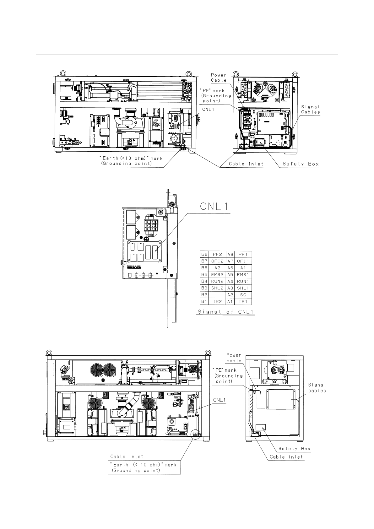
B-70315EN/01 4.INSTALLATION
Fig.4.4.3.1(a) Cable connection (C1000-E)
Fig.4.4.3.1(b) Location of CNL1 (C1000-E)
Fig.4.4.3.1(c) Cable connection of (C2000-E)
- 79 -

4.INSTALLATION B-70315EN/01
Fig.4.4.3.1(d) Cable connection (C4000-E)
Fig.4.4.3.1(e) Location of CNL1 (C2000-E, C4000-E)
c) OFF interlock signals (OFI1 and OFI2)
Making the power supply for the oscillator ready to be
switched off turns off these signals. Connect them in
parallel with an CNC OFF switch.
Contact current-carrying capacity : 3 A on 250 VAC or 5 A
on 30 VDC
d) Laser oscillator ON/OFF signal (ON, OFF)
Connect 200 VAC in synchronization with the CNC
ON/OFF switch to this signal.
Current-carrying capacity : 10 mA on 200 VAC
- 80 -

B-70315EN/01 4.INSTALLATION
4) CNL1 terminal
B8 PF2 A8 PF1
B7 OFI2 A7 OFI1
B6 A2 A6 A1
B5 EMS2 A5 EMS1
B4 RUN2 A4 RUN1
B3 SHL2 A3 SHL
B2 A2 SC
B1 IB2 A1 IB1
CNL1 pin arrangement (as viewed from the wiring surface)
a) PF1 and PF2
These terminals are for QF1 voltage tripping. Connect
+24 VDC and 0 V to PF1 and PF2, respectively.
b) SHL1 and SHL2
These terminals are for shutter interlocking. Strapping
these terminals enables the shutter to be opened and closed.
Contact current-carrying capacity : At least 1.2 A on 24
VDC
Wire: 1.25 mm2, 25 m or shorter
c) IB1 and IB2
These terminals are for semiconductor laser interlocking.
Strapping these terminals enables the semiconductor laser
to be turned on.
Contact current-carrying capacity: At least 10 mA on 30
VDC
d) A1 and A2
These terminals are for supplying power to the safety box
in the laser oscillator and switching on and off the laser
oscillator power supply.
Connect +24 VDC and 0 V to A1 and A2, respectively.
Current-carrying capacity: At least 250 mA
e) SC
This terminal is for outputting a shutter-closed signal. It
outputs the signal when the shutter is closed.
Connectable load capacity: 3 to 100 mA on 24 VDC
Note that the voltage applied to the load varies with the
current flowing through the load.
f) RUN1 and RUN2
Connect these terminals in series with the laser oscillator
start signal.
g) EMS1 and EMS2
Connect these terminals to emergency stop switch contact
signals.
- 81 -

4.INSTALLATION B-70315EN/01
4.4.3.2 Details of safety circuit
The figure shows the safety circuit for each oscillator.
Fig.4.4.3.2(a) Safety circuit of C11000-E
- 82 -

B-70315EN/01 4.INSTALLATION
Fig.4.4.3.2(b) Safety circuit of C2000-E
- 83 -

4.INSTALLATION B-70315EN/01
Fig.4.4.3.2(c) Safety circuit of C4000-E
- 84 -
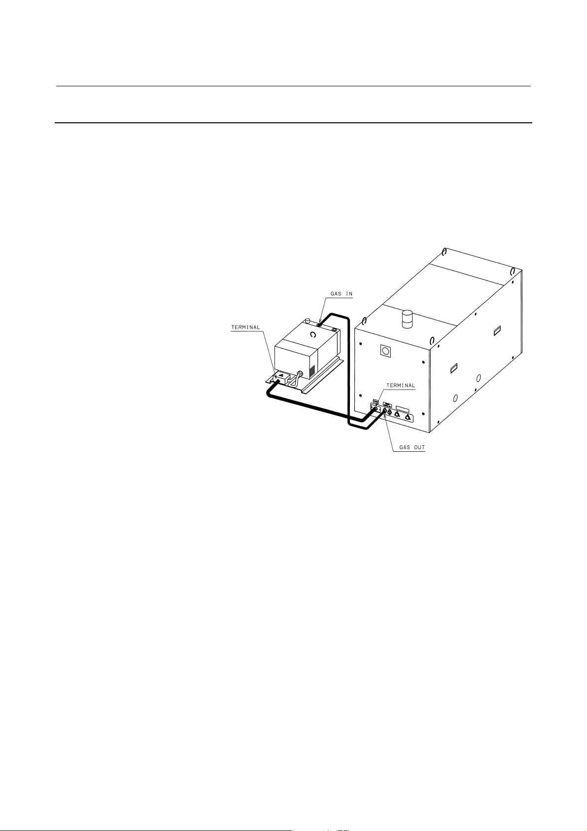
B-70315EN/01 4.INSTALLATION
4.4.4 Inter-unit Connections
The C1000-E has an oscillator section and exhaust pump section.
Interconnection is made according to the procedure described below.
(1) Connection of the exhaust pump power cable
Use the supplied cable. Connect it correctly (with the correct
phase sequence).
(2) Gas piping
Fig.4.4.4 Connection of exhaust pump (C1000-E)
- 85 -

5.MAINTENANCE B-70315EN/01
5 MAINTENANCE
In FANUC LASER C1000/C2000/C4000-MODEL E, periodic
inspection items have been reduced, and adjustments have been made
easy. To keep the oscillator in a satisfactory operating condition over
a long period, however, it is necessary to carry out periodic
maintenance (including daily maintenance) described in this chapter.
The oscillator is designed to maintain the same performance and
reliability as it has when it is installed, provided that maintenance is
carried out as prescribed.
- 86 -

B-70315EN/01 5.MAINTENANCE
5.1 DAILY INSPECTION
Table 5.1 lists daily inspection items. Inspect the FANUC LASER
C1000/C2000/C4000-MODEL E according to this table. When parts
(including oil) have been used for a prescribed period, replace them
quickly.
Table 5.1 Daily inspection items for FANUC LASER C1000/C2000/C4000-MODEL E
Item Period Content and instruction
Check to see if the primary pressure is 1.0 MPa or less as measured at the
1 Residual laser gas Daily
2 Exhaust pump oil Weekly
3 Exhaust pump oil leak Weekly
4 Turbo blower oil We ekly
5 Turbo blower oil leak Weekly
6 Laser output Weekly
Daily Make sure that the chiller discharge output is 0.5 MPa or less.
7 Cooling water
Weekly
regulator on the laser gas cylinder. If the primary pressure is 1.0 MPa or lower,
replace the gas cylinder. See Section 4.4.2 for the gas specifications.
Make sure that the oil level is between L (minimum) and H (maximum). Usually,
oil is supplied until the oil level is in the middle between L and H. If the oil level is
below L, supply oil according to Section 5.3.2. Be sure to replace the oil
periodically, every 6 months of use or every 1500 hours of operation, whichever
is earlier.
Make sure that no oil is leaking from the vane pump main body, drain cock and
their periphery. If oil is leaking, immediately replace the exhaust filter according
to Section 5.3.3, because it is likely to have been clogged. Be sure to replace the
exhaust filter periodically, every one year of use or every 3000 hours of
operation, whichever is earlier.
Make sure that the oil level is between L (minimum) and H (maximum) according
to Fig. 5.3.1. Usually , oil is suppled until the oil level is at 3/4 above L. If the oil
level is below L, supply oil according to Section 5.3.1. Be sure to replace the oil
periodically, every 4 months of use or 1000 hours of operation, whichever is
earlier.
Make sure that no oil is leaking from the turbo blower main body, oil inlet, cock,
and their periphery. If oil is leaking, locate the leak. If oil leaks for any reason
other than a cock being open, call FANUC.
1. Check to see if the laser output measured at the outlet of the short optical path
oscillator is 5% or more lower than the specified output. If this is the case,
clean or replace the optical components in the external reflection unit.
2. If the laser output decreases within the oscillator, warning message No. 4085
is issued. If this message appears, clean or replace the mirror in the oscillator
quickly.
Check the quality of cooling water circulating in the chiller. If the water is colored
badly, replace it completely. Be sure to replace the cooling water every two
months. Adding an anticorrosive to cooling water can decrease the replacement
frequency. See Section 4.4.1.2 for descriptions about the anticorrosive.
- 87 -

5.MAINTENANCE B-70315EN/01
5.2 PERIODIC MAINTENANCE
Table 5.2 shows the periodic maintenance items and the periods. The
operation hour can be known from the indication of hour meter. When
the indicated periods are more than one, employ the one whichever
comes first.
Table 5.2(a) Periodic maintenance items and periods
Item
1 Output mirror cleaning
2 Rear mirror cleaning
3 Folding mirror cleaning 3000 to 4000 h
4 0-shift mirror cleaning 1000h or processing quality go wrong
5 Output mirror change
6 Rear mirror change
7 Folding mirror change 4000h or inferior beam mode
8 0-shift mirror change 3000h or inferior beam mode
9 Exhaust pump oil change 1500h or low exhaust ability
10 Exhaust pump filter change 3000h or low exhaust ability
11 Exhaust pump overhaul 10000h or low exhaust ability
12 Turbo blower oil change 1000h or inferior turbo blower oil
13 Turbo blower overhaul 12000h or low turbo blower ability
14 Pressure control filter change 12000h or pressure alarm occurs
15 Discharge tube O-ring change 6000h or intra-cavity leakage occurs
16 Cooling water 1500h or inferior water quality
17 Water tubing cleaning 3000h or water flow is blocked
18 Beam absorber 15000h or over heat alarm occurs
19 Nylon tube 15000h
20 Cable 15000h
C1000-E C2000-E C4000-E
1500 to 2000 h 1500 to 2000 h 800 to 1200 h
Interval of maintenance (Operation hour)
4000h or inferior beam mode
3000h or inferior beam
mode
- 88 -

B-70315EN/01 5.MAINTENANCE
5.3 DETAILS OF MAINTENANCE
When opening the panels and doors during maintenance, keep the
power turned off. Before replacing oil, be sure to check that purging
is completed.
Fig.5.3(a) Oil gauge of turbo blower and exhaust pump (C1000-E)
- 89 -

5.MAINTENANCE B-70315EN/01
Fig.5.3(b) Oil gauge of turbo blower and exhaust pump (C2000-E)
Fig.5.3(c) Oil gauge of turbo blower and exhaust pump (C4000-E)
- 90 -

B-70315EN/01 5.MAINTENANCE
5.3.1 Turbo Blower Oil
(1) Check method
Check the amount of oil in the turbo blower while referring to
the figure below. The oil level should be between graduations H
and L. This check should be made when the oscillator is at a rest.
When the turbo blower is running, it is impossible to check the
amount of oil correctly.
(2) Replenishment method
1) Remove the hexagonal-head screw from the oil inlet with a
17 mm wrench. Be careful not to lose the O-ring on the
screw. Before supplying turbo oil, stop the oscillator
according to the correct procedure and turn off the power. If
the oscillator is not stopped by the correct procedure, the
pressure in the turbo blower becomes negative. Opening the
oil inlet under such a condition lets a large amount of air
get in the turbo blower. An air flow caused this way can
bring oil mist into the oscillator, possibly resulting in the
optical mirror getting dirty.
2) Take a bottle of oil from the oil kit (A04B-0800-K326).
Unscrew the nozzle from the bottle, remove the inner cap,
then replace the nozzle. Insert the nozzle into the oil inlet
and supply oil. Be careful not to allow dust to enter
through the inlet. This task is made easier by attaching the
tube (included in the oil kit) onto the nozzle. Supply oil
until the oil reaches the 3/4 level relative to the L indication
when viewed through the oil window. Note that both too
little and too much oil can result in mechanical failure.
3) Clean the oil inlet, hexagonal-head screw of the oil inlet,
and O-ring by wiping with a clean cloth or paper. Ensure
that these parts are completely free of dust. If the oil is
contaminated with dust, the turbo blower may fail. Set the
O-ring in the groove around the hexagonal-head screw of
the oil inlet, then tighten the hexagonal-head screw. Note
that if the O-ring is not set correctly, or if the hexagonalhead screw is not tightened fully, the turbo blower may not
be air-tight.
4) If oil has spilled over, wipe it up. Otherwise, the
peripheral equipment may be affected adversely.
5) If there is oil left over, put the inner lid back on the bottle,
and keep the bottle in a dark, cool place.
(3) Replacement method
1) Get a container for oil drain on hand, and put the tip of the
drain tube into the container.
2) Turn the oil drain cock through 905 clockwise, and the oil
will start draining.
3) After all the oil has been drained, close the oil drain cock
by setting it back in the initial place.
4) Supply oil by following the same procedure as for
replenishment.
- 91 -

5.MAINTENANCE B-70315EN/01
NOTE
Execute discharge ageing after changing turbo
blower oil.
Fig.5.3.1 Turbo blower oil check points
- 92 -
 Loading...