


SERVICE MANUAL
Color Inkjet Printer
SCP600
SE GROUP CONFIDENTIAL (RELATED STAFF ONLY)
SEIJ 14-005
Notice:
All rights reserved. No part of this manual may be reproduced, stored in a retrieval system, or transmitted in any form or by any means, electronic, mechanical, photocopying, recording, or otherwise, without the prior written permission of SEIKO EPSON CORPORATION.
All effort have been made to ensure the accuracy of the contents of this manual. However, should any errors be detected, SEIKO EPSON would greatly appreciate being informed of them.
The contents of this manual are subject to change without notice.
The above not withstanding SEIKO EPSON CORPORATION can assume no responsibility for any errors in this manual or the consequences thereof.
EPSON is a registered trademark of SEIKO EPSON CORPORATION.
Note :Other product names used herein are for identification purpose only and may be trademarks or registered trademarks of their respective owners. EPSON disclaims any and all rights in those marks.
Copyright 2014 SEIKO EPSON CORPORATION
COMMERCIAL PRINTER PRODUCT DEPT.
SE Group Confidential (Related Staff Only)
Safety Precautions
All safety procedures described here shall be strictly adhered to by all parties servicing and maintaining this product.
DANGER
Strictly observe the following cautions. Failure to comply could result in serious bodily injury or loss of life.
1.Always disconnect the product from the power source and peripheral devices when servicing the product or performing maintenance.
2.When performing works described in this manual, do not connect to a power source until instructed to do so. Connecting to a power source causes high voltage in the power supply unit and some electronic components even if the product power switch is off. If you need to perform the work with the power cable connected to a power source, use extreme caution to avoid electrical shock.
WARNING
Strictly observe the following cautions. Failure to comply may lead to personal injury or loss of life.
1.Always wear protective goggles for disassembly and reassembly to protect your eyes from ink in working. If any ink gets in your eyes, wash your eyes with clean water and consult a doctor immediately.
2.When using compressed air products; such as air duster, for cleaning during repair and maintenance, the use of such products containing flammable gas is prohibited.
PRECAUTIONS
Strictly observe the following cautions. Failure to comply may lead to personal injury or damage of the product.
1.Repairs on Epson product should be performed only by an Epson certified repair technician.
2.No work should be performed on this product by persons unfamiliar with basic safety knowledge required for electrician.
3.The power rating of this product is indicated on the serial number/rating plate. Never connect this product to the power source whose voltages is different from the rated voltage.
4.Replace malfunctioning components only with those components provided or approved by Epson; introduction of second-source ICs or other non-approved components may damage the product and void any applicable Epson warranty.
5.In order to protect sensitive microprocessors and circuitry, use static discharge equipment, such as anti-static wrist straps, when accessing internal components.
6.Do not tilt this product immediately after initial ink charge, especially after performing the ink charge several times. Doing so may cause ink to leak from the product because it may take some time for the waste ink pads to completely absorb ink wasted due to the ink charge.
7.Never touch the ink or wasted ink with bare hands. If ink comes into contact with your skin, wash it off with soap and water immediately. If you have a skin irritation, consult a doctor immediately.
SE Group Confidential (Related Staff Only)
8.When disassembling or assembling this product, make sure to wear gloves to avoid injuries from metal parts with sharp edges.
9.Use only recommended tools for disassembling, assembling or adjusting the printer.
10.Observe the specified torque when tightening screws.
11.Be extremely careful not to scratch or contaminate the following parts.
Nozzle plate of the printhead
Ink Supply Unit
CR Scale
PF Scale
Coated surface of the PF Roller
Gears
Rollers
LCD
Exterior parts
12.Never use oil or grease other than those specified in this manual. Use of different types of oil or grease may damage the component or give bad influence on the printer function.
13.Apply the specified amount of grease described in this manual.
14.Make the specified adjustments when you disassemble the printer.
15.When cleaning this product, follow the procedure described in this manual.
16.When transporting this product after filling the ink in the printhead, pack the printer without removing the ink cartridges in order to prevent the printhead from drying out.
17.Make sure to install antivirus software in the computers used for the service support activities.
18.Keep the virus pattern file of antivirus software up-to-date.
SE Group Confidential (Related Staff Only)

About This Manual
About This Manual: This manual is made for the sole purpose of providing necessary information in order that a serviceperson qualified by Epson performs his / her appropriate repair / maintenance for the applicable Epson’s products. You shall not use this manual out of this purpose.
This manual is Epson’s confidential information. When you use this manual, you shall hold it in strict confidence and shall not disclose to any third party without prior consent of Epson.
This manual, consists of the following chapters, is intended for repair service personnel and includes information necessary for properly performing maintenance and servicing the product.
CHAPTER 1. DISASSEMBLY / REASSEMBLY
Describes the disassembly/reassembly procedures for main parts/units of the product, and provides the standard operation time for servicing the product.
CHAPTER 2. ADJUSTMENT
Describes the required adjustments for servicing the product.
CHAPTER 3. MAINTENANCE
Describes maintenance items and procedures for servicing the product.
CHAPTER 4. APPENDIX
Provides the following additional information for reference:
•Power-On Sequence
•Connector Diagram
Symbols Used in this Manual
Various symbols are used throughout this manual either to provide additional information on a specific topic or to warn of possible danger present during a procedure or an action. Pay attention to all symbols when they are used, and always read explanation thoroughly and follow the instructions.
Indicates an operating or maintenance procedure, practice or condition that, if not strictly observed, could result in serious injury or loss of life.
Indicates an operating or maintenance procedure, practice, or condition that, if not strictly observed, could result in bodily injury, damage or malfunction of equipment.
May indicate an operating or maintenance procedure, practice or condition that is necessary to accomplish a task efficiently. It may also provide additional information that is related to a specific subject, or comment on the results achieved through a previous action.
For Chapter 1 “Disassembly/Reassembly”, symbols other than indicated above are used to show additional information for disassembly/reassembly. For the details on those symbols, see "1.2 Disassembly/Reassembly Procedures (p14)".
SE Group Confidential (Related Staff Only)

Revision Status
Revision |
Date of Issue |
Description |
|
|
|
A |
September 30, 2014 |
First Release |
|
|
|
B |
February 12, 2015 |
Chapter 1 |
|
|
- "1.1.2 Jigs (p10)": calibrator names were revised. |
|
|
Chapter 2 |
|
|
- "2.1 Adjustment Items and the Order by Repaired Part (p32)": adjustment items when Print |
|
|
Head was removed were revised. |
|
|
- "2.2 Adjustment Items (p36)": description about Colorimetric calibration was revised. |
|
|
- "2.3.7 Head Angular Adjustment CR/PF (p55)": partially revised. |
|
|
- "2.3.8 Colorimetric Calibration (p57)": contents were added newly. |
|
|
|
C |
March 31, 2015 |
Chapter 1 |
|
|
- "1.1 Overview (p9)": “WARNING” was added |
|
|
- "1.1.1 Tools (p9)": “CAUTION” was added |
|
|
|
D |
November 24, 2015 |
Chapter 2 |
|
|
- "2.2 Adjustment Items (p36)": Note was added outside of Table2-3. |
|
|
- "2.3.6 Initial setting (p54)": partially revised. |
|
|
- "2.3.7 Head Angular Adjustment CR/PF (p55)": procedure was revised. |
|
|
- "2.3.10 Touch screen adjustment (p70)": contents were added newly. |
|
|
|
SE Group Confidential (Related Staff Only)

SC-P600 |
Revision D |
Contents
Chapter 1 Disassembly/Reassembly
1.1 |
Overview |
.................................................................................................................... ............................................... |
9 |
|
|
1.1.1 |
Tools ................................................................................................................................................................. |
9 |
|
|
1.1.2 |
Jigs .................................................................................................................................................................. |
|
10 |
|
1.1.3 |
Precautions ..........................................................................................before Disassembling ........................ |
11 |
|
|
1.1.4 |
Preparation .........................................................................before Returning the Unit to the User ................ |
12 |
|
1.2 |
Disassembly/Reassembly ...........................................................................................Procedures .......................... |
14 |
||
|
1.2.1 Disassembly/Reassembly ..........................................................................................Flowchart .................... |
15 |
||
|
1.2.1.1 ............................................................................................................ |
Housing Part .............................. |
15 |
|
|
1.2.1.2 .................................................................................................. |
Printer Mechanism Part ....................... |
16 |
|
1.3 |
Detailed Disassembly/Reassembly ................................................................Procedure for each Part/Unit ........... |
19 |
||
1.4 |
Routing FFCs/cables ............................................................................................................................................... |
28 |
||
Chapter 2 Adjustment |
|
|||
|
|
|
||
2.1 |
Adjustment Items and the Order by Repaired Part.................................................................................................. |
32 |
||
2.2 |
Adjustment ............................................................................................................Items ........................................ |
36 |
||
2.3 |
Details of ......................................................................................................Adjustments ...................................... |
39 |
||
|
2.3.1 PF Timing .........................................................................................Belt Tension Adjustment ..................... |
39 |
||
|
2.3.2 |
PF Roller ........................................................................Shaft Center Support Position Adjustment ............ |
40 |
|
|
2.3.3 ASF ..................................................................................Guide Roller LDs position adjustment ................. |
46 |
||
|
2.3.4 PG Adjustment ............................................................................................................................................... |
49 |
||
|
2.3.5 Mist .......................................................................................................Recovery check ............................... |
53 |
||
|
2.3.6 |
Initial ...........................................................................................................setting ........................................ |
54 |
|
|
2.3.7 Head .............................................................................................Angular Adjustment CR/PF ..................... |
55 |
||
|
2.3.8 |
Colorimetric ..................................................................................................Calibration ............................... |
57 |
|
|
2.3.8.1 ................................................................................ |
Overview of the Colorimetric Calibration ............. |
57 |
|
|
2.3.8.2 ........................................................................ |
Adjusting Method of the Colorimetric Calibration |
........ 60 |
|
|
2.3.8.3 ........................................................................................................Maintenance menu ......................... |
68 |
||
|
2.3.9 |
Ink Selector ........................................................................................................Check .................................. |
69 |
|
|
2.3.10 Touch ..................................................................................................screen adjustment ............................ |
70 |
||
Chapter 3 Maintenance |
|
|||
|
|
|
|
|
3.1 |
Overview ................................................................................................................................................................. |
|
72 |
|
|
3.1.1 |
Cleaning.......................................................................................................................................................... |
72 |
|
|
3.1.2 |
Lubrication...................................................................................................................................................... |
72 |
|
3.2 |
Lubrication .........................................................................................Points and Instructions ................................ |
73 |
||
Chapter 4 Appendix |
|
|||
|
|
|
||
4.1 |
Power-On Sequence ................................................................................................................................................ |
77 |
||
4.2 |
Connector ...........................................................................................................Diagram ...................................... |
80 |
||
4.3 |
Fatal Error ............................................................................................................Code .......................................... |
81 |
||
7
SE Group Confidential (Related Staff Only)

CHAPTER 1
DISASSEMBLY/REASSEMBLY
SE Group Confidential (Related Staff Only)
SC-P600 |
Revision D |
1.1 Overview
This chapter describes procedures for disassembling the main parts/units of Stylus Photo R3000. Unless otherwise specified, disassembled parts/units can be reassembled by reversing the disassembly procedure. See the cautions or tips for disassembly/reassembly described in "1.3 Detailed Disassembly/Reassembly Procedure for each Part/Unit (p19)".
Read the "Safety Precautions (p3)" before disassembling and reassembling.
When you have to remove units or parts that are not described in this chapter, see the exploded diagrams of SPI (Service Parts Information).
This warning is for Taiwan.
1.1.1 Tools
Use only specified tools to avoid damaging the printer.
Name |
Availability*1 |
EPSON Part Code*2 |
(+) Phillips screwdriver #1 |
O |
1080530 |
|
|
|
(+) Phillips screwdriver #2 |
O |
--- |
|
|
|
Flathead screwdriver |
O |
--- |
|
|
|
Flathead Precision screwdriver #1 |
O |
--- |
|
|
|
Tweezers |
O |
--- |
|
|
|
Longnose pliers |
O |
--- |
|
|
|
Acetate tape |
--- |
1003963 |
|
|
|
Nippers |
O |
--- |
|
|
|
Note *1: Some of the tools listed above are commercially available. *2: EPSON provides the tools listed with EPSON part code.
Bring back the following brought and used items, then dispose of them based on the local regulations in your country, please.
Ink cartridges
Cleaning cartridges
Draining cartridges
Especially in case of ink cartridges in Europe, please refer to the following web site to confirm the regulation in detail.
ECO Info: http://www.epson.eu/weee (available from July 2015)
Disassembly/Reassembly |
Overview |
9 |
SE Group Confidential (Related Staff Only)

SC-P600 Revision D
1.1.2 Jigs
Name*1 |
Q’ty |
Availability*2 |
EPSON Part Code |
Sonic tension gauge U-508 |
1 |
--- |
1640645 |
|
|
|
|
PF Roller Adjustment Jig |
1 |
--- |
1553098 |
|
|
|
|
PF Roller Adjustment Jig Stand |
1 |
--- |
1553099 |
|
|
|
|
Level block |
1 |
--- |
1304994 |
|
|
|
|
Adjustment gauge for PG adjustment |
1 |
--- |
1276333 |
|
|
|
|
Oscilloscope or Tester + High-voltage probe |
1 |
O*3 |
--- |
Calibrator (i1 Pro UV-Cut or i1Pro2) |
1 |
O |
--- |
|
|
|
|
Note *1: The jigs above are used for adjustment (See Chapter 2 " Adjustment (p31)".) No jigs are required for disassembling/ reassembling this printer.
*2: Some of the tools listed above are commercially available.
*3: Recommended maker and model number: (If the device which can measure resistance value of 100MΩ is not used, you may not measure a value definitely. As a result, there is the case that a parameter is not set within a standard, the Mist Recovery Function does not act, and dirt in the printer or printing back side dirt of the paper occur.)
Oscilloscope + High-voltage probe (A high voltage probe around 100MΩ made by Tektronix: P-5210A or THDP0100)
Tester (Ex. FLUKE True-rms Multimeter 110 Series, 3+1/2 columns of DMM: More than input 10MΩ) + High voltage probe (around 75MΩ: FLUKE 80K-6 or 80K-40)
Disassembly/Reassembly |
Overview |
10 |
SE Group Confidential (Related Staff Only)
SC-P600 |
Revision D |
1.1.3 Precautions before Disassembling
Unlocking the carriage
Unlock the carriage by following the procedure below.
1.Remove the Rear Housing, Right Cover, and Right Decoration Plate.
2.Insert a phillips screwdriver into the hole of the frame on the right side of the printer, and rotate the white shaft of the Ink System.
Table 1-1. Carriage Lock/Unlock
Direction of Rotation |
Carriage |
|
|
Clockwise (CW) |
Locked |
|
|
Counterclockwise (CCW) |
Unlocked |
|
|
Right
CCW

 CW
CW
|
|
Hole |
Phillips screwdriver |
|
|
|
|
|
Figure 1-1. Unlock the Carriage
Handling the Ink Supply Unit
In order to prevent ink leakage, be careful of the following when handling the Ink Supply Unit. (See "Ink Supply Unit (p22)" and "CR Contact Module (p22)" for details.)
Unless otherwise specified in this manual, do not disassemble the Ink Supply Unit any further than specified as an ASP. Otherwise, replace the Ink Supply Unit with a new one.
Be careful not to damage the film of the ink path.
When disassembling/reassembling the printer, be careful not to apply extra force on the joint part of the ink tube and I/C Holder Unit, and on that of the ink tube and Ink Selector.
Disassembly/Reassembly |
Overview |
11 |
SE Group Confidential (Related Staff Only)
SC-P600 |
Revision D |
1.1.4 Preparation before Returning the Unit to the User
When returning the printer to the user, make sure to secure the specified points with tapes to avoid damaging the printer during transport.
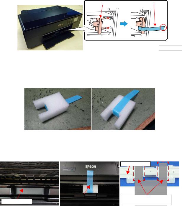
Attaching the front tray lock (tape length: 90 ± 2 mm, tape width: 18 mm, fold one end by 5 mm) Attach the front tray lock (1535369) and secure it with strong tape as follows.
1.Attach the front tray lock on the position shown in Figure 1-2.
2.Attach the unfolded end of strong tape on the front tray lock as shown in Figure 1-2, and pull the tape and apply it along the shapes of the Upper Housing Support Assy to secure the front tray lock.
|
|
|
|
|
Front tray lock |
|
|
Strong tape |
||
|
|
|
|
|
|
|
|
|
|
|
|
|
|
|
|
|
|
|
|
|
|
|
|
|
|
|
|
|
|
|
|
|
|
|
|
|
|
|
|
|
|
|
|
|
|
|
|
|
|
|
|
|
|
|

 Folded end
Figure 1-2. Attaching and Securing the Front Tray Lock
Attaching the front tray support pad (tape length: 190mm, tape width: 18 mm, fold one end by 5 mm) Attach the front tray support pad (5125513) and secure it with strong tape as follows.
1. Attach the strong tape to the front tray support pad shown in Figure 1-3.
|
|
|
|
|
Upper of Pad |
|
|
Lower of Pad |
|
|
|
|
|
|
Figure 1-3. Attaching the strong tape to the front tray
2. Attach the front tray support pad to the front of the printer shown in Figure 1-4.
Tray Suppot Assy
|
|
|
|
|
|
|
|
|
|
|
|
|
|
|
|
|
|
|
|
|
|
|
|
|
|
|
|
|
|
|
|
|
|
|
|
|
|
|
|
|
|
|
|
|
|
|
|
|
|
|
|
|
|
|
|
|
|
|
|
|
|
|
|
|
|
|
|
|
|
|
|
|
|
|
|
|
|
|
|
|
|
|
|
|
|
|
|
|
|
|
|
|
|
|
|
|
|
|
|
|
|
|
|
|
|
|
|
|
|
|
|
|
|
|
|
|
|
|
|
|
|
|
|
|
|
|
|
|
|
|
|
|
|
|
|
|
|
|
|
|
|
|
|
|
|
|
|
|
|
|
|
|
|
|
|
|
|
|
|
|
|
|
|
|
|
|
|
|
|
|
|
|
|
|
|
|
|
|
|
|
|
|
|
|
|
|
|
|
|
|
|
|
|
|
|
|
|
|
|
|
|
|
|
|
|
|
|
|
|
|
|
|
|
|
|
|
|
|
|
|
Attach the unfolded end of tape |
||||||
Attaching area |
|
|
|
|
|
|
|
to the front of the printer. |
||||||||||
|
|
|
|
|
|
|
|
|
|
|
|
|
|
|
|
|
|
|
|
|
|
|
|
|
|
|
|
|
|
|
|
|
|
|
|
|
|
The location of the projections of pad is between roller and claw.
Figure 1-4. Attaching the front tray support pad
Disassembly/Reassembly |
Overview |
12 |
SE Group Confidential (Related Staff Only)

SC-P600 |
Revision D |
Securing the CR Unit (tape length: 220 ± 2 mm, tape width: 18 mm, fold one end by 5 mm) Secure the CR Unit with strong tape as follows.
1.Open the printer cover and move the CR Unit to its home position.
2.Attach the unfolded end of strong tape on the CR Unit, and pull the tape and apply it along the shapes of the Upper Housing Assy to the right side of the printer to secure the CR Unit.
Attach strong tape with its unfolded end sticking out of the printer.
CR Unit
Strong tape
Figure 1-5. Securing the CR Unit
Disassembly/Reassembly |
Overview |
13 |
SE Group Confidential (Related Staff Only)
SC-P600 |
Revision D |
1.2 Disassembly/Reassembly Procedures
This section describes procedures for disassembling the parts/units in a flowchart format. For some parts/units, detailed procedures or precautions are provided (accordingly indicated by icons and cell’s color). Refer to the explanations in the example chart below and perform an appropriate disassembling and assembling procedure. (See "1.3 Detailed Disassembly/Reassembly Procedure for each Part/Unit (p19)".)
For routing cables, see "1.4 Routing FFCs/cables (p28)".
The example below shows how to see the charts on the following pages.
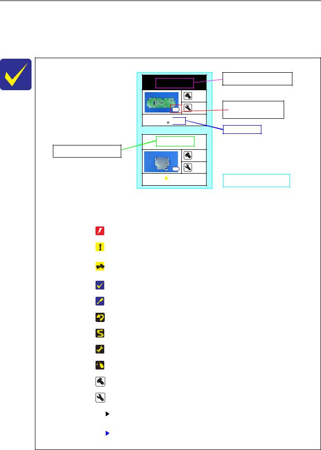
Black letters indicate a part/ unit not supplied as an ASP.
Panel Board
2
S12 4

 (p 15)
LCD Shield
|
2 |
S4 |
2 |
|
 (p 15)
White letters indicate a part/ unit supplied as an ASP.
Shows the screw types and specified torque in the
“Screw type/torque list”.
Reference page
Shows removal/installation  as a unit/assy. is available.
Item |
Description |
Reference |
||||
|
|
|
|
|
|
|
Parts/unit name |
White-letter |
Part/unit supplied as an ASP |
--- |
|||
|
|
|
|
|
||
Black-letter |
Part/unit not supplied as an ASP |
--- |
||||
|
||||||
|
|
|
|
|
|
|
|
|
|
|
Indicates a practice or condition that could result in injury or |
Indicates the reference |
|
|
|
|
|
loss of life if not strictly observed. |
page in blue-letter |
|
|
|
|
|
|
|
|
|
|
|
|
Indicates a practice or condition that could result in damage to, |
Indicates the reference |
|
|
|
|
|
or destruction of equipment if not strictly observed. |
page in blue-letter |
|
|
|
|
|
|
|
|
|
|
|
|
Indicates the parts that are inevitably broken in the |
|
|
|
|
|
|
disassembling procedure, and should be replaced with a new |
--- |
|
|
|
|
|
one for reassembly. |
|
|
|
|
|
|
|
|
|
|
|
|
|
Indicates necessary check items in the disassembling/ |
Indicates the reference |
|
|
|
|
|
assembling procedure. |
page in blue-letter |
|
|
|
|
|
|
|
|
|
|
|
|
Indicates supplementary explanation for disassembly is given. |
Indicates the reference |
|
|
|
|
|
page in blue-letter |
||
|
|
|
|
|
||
Icon |
|
|
|
|
|
|
|
|
|
Indicates particular tasks to keep quality of the units are |
Indicates the reference |
||
|
|
|
|
required. |
page in blue-letter |
|
|
|
|
|
|
|
|
|
|
|
|
Indicates particular routing of cables is required. |
Indicates the reference |
|
|
|
|
|
page in blue-letter |
||
|
|
|
|
|
||
|
|
|
|
|
|
|
|
|
|
|
Indicates particular adjustment(s) is/are required. |
Chapter 2 " Adjustment |
|
|
|
|
|
(p31)" |
||
|
|
|
|
|
||
|
|
|
|
|
|
|
|
|
|
|
Indicates lubrication is required. |
Chapter 3 " Maintenance |
|
|
|
|
|
(p71)" |
||
|
|
|
|
|
||
|
|
|
|
|
|
|
|
|
|
|
Indicates the number of screws securing the parts/units. |
--- |
|
|
|
|
|
|
|
|
|
|
|
|
Indicates the points secured with other than a screw such as a |
--- |
|
|
|
|
|
hook, rib, dowel or the like |
||
|
|
|
|
|
||
|
|
|
|
|
|
|
Arrowed line |
|
|
|
Indicates a disassembling procedure. |
--- |
|
|
|
|
||||
|
|
|
|
|
||
|
|
|
Indicates a removal procedure for a component of a part or |
|
||
|
|
|
|
|
||
|
|
|
|
unit which is necessary to remove when proceeding to the |
--- |
|
|
|
|
|
|||
|
|
|
|
target part. |
|
|
|
|
|
|
|
|
|
Disassembly/Reassembly |
Disassembly/Reassembly Procedures |
14 |
SE Group Confidential (Related Staff Only)
SC-P600 |
Revision D |
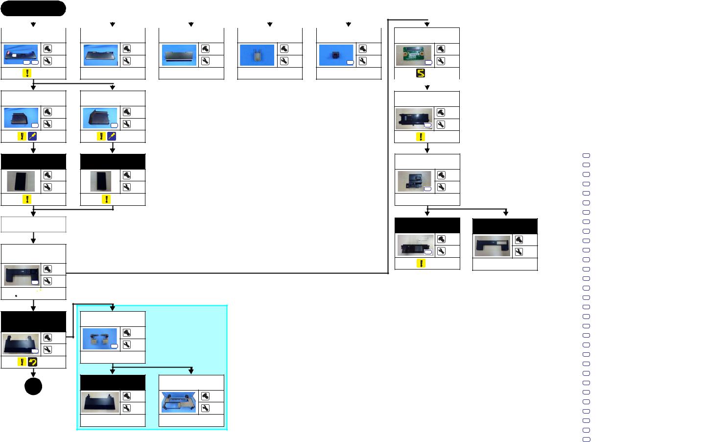
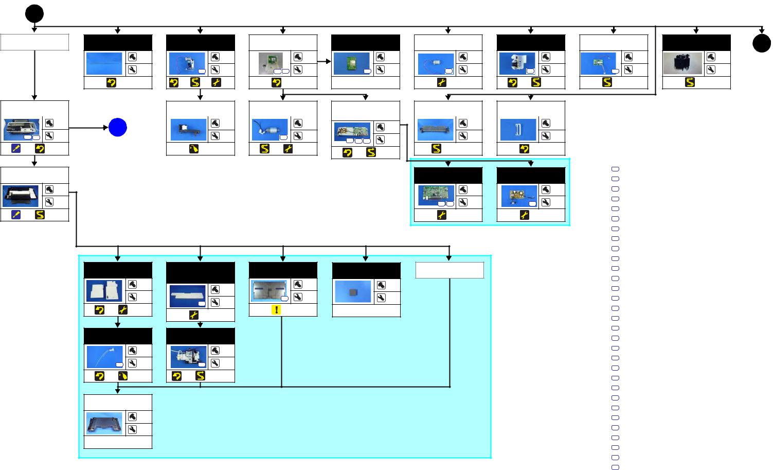
1.2.1 Disassembly/Reassembly Flowchart
1.2.1.1 Housing Part
START
|
|
|
|
|
|
|
|
|
|
|
|
|
|
|
|
|
|
|
|
|
|
|
|
|
|
|
|
|
|
|
|
|
|
|
|
|
|
|
|
|
|
|
|
|
|
|
|
|
|
|
|
|
|
|
|
|
|
|
|
|
|
|
|
|
|
|
|
|
|
|
|
Rear Housing |
|
|
Paper Support |
|
Stacker Cover |
|
CSIC Terminal |
|
Adjust Printer |
|
Panel SUB |
||||||||||||
|
Assy |
|
|
|
Cover |
|
Board |
||||||||||||||||
|
|
|
|
|
|
|
|
|
|
|
|
|
|
|
|||||||||
|
|
|
|
|
|
|
|
|
|
|
|
|
|
|
|
|
|
|
|
|
|
|
|
|
|
3 |
--- |
--- |
--- |
|
1 |
|
2 |
S9 |
S20 |
12 |
4 |
2 |
2 |
S5 |
--- |
S12 |
--- |
|
|
(p 19) |
--- |
--- |
--- |
--- |
|
|
(p 28) |
||||
|
|
|
|
|
|
|
|
|
|
|
|
|
|
|
|
|
|
|
|
|
|
|
|
|
|
|
|
|
|
|
|
|
|
|
|
|
|
|
|
|
|
|
|
|
|
|
|
|
|
|
|
|
|
|
|
Left Cover |
|
Right Cover |
Panel Cover |
|
Rear |
||
|
|
|
|
|
|
|
|
|
1 |
|
1 |
|
3 |
S5 |
4 |
S5 |
4 |
S12 |
--- |
(p 19) |
(p 19) |
(p 20) |
|
|
Left |
Right |
Cover Open |
|
|
Decoration Plate |
Decoration Plate |
Sensor Cover |
|
|
--- |
--- |
|
1 |
|
3 |
3 |
S12 |
--- |
|
|
|
|
|
|
(p 19) |
(p 19) |
--- |
|
|
Adjust Printer |
|
Panel Unit |
|
Upper Housing |
Cover |
|
|
||
|
|
Support Assy |
||
|
|
|
|
|
|
|
|
4 |
--- |
Upper Housing |
|
S12 |
--- |
--- |
Support Assy |
|
|||
(w/Panel Unit) |
|
|
|
|
4 |
|
(p 20) |
|
--- |
|
|
|
|
S6 14
 (p 19)
  (p 28)
Upper Housing |
Upper Printer |
|
|
Assy (w/Upper |
Cover Holder |
|
|
Printer Cover) |
|
|
|
|
4 |
6 |
|
|
|
|
|
|
S12 |
10 |
|
S13 |
--- |
|
|
|
--- |
|
|
(p 19) |
|
|
|
1 |
Upper Printer |
|
Upper Housing |
Cover |
|
||
|
|
||
(p 16) |
|
--- |
--- |
|
|
|
|
|
|
--- |
--- |
|
--- |
|
--- |
Screw type/torque list
Symbol |
Screw type |
Torque |
|
|
|
S1 |
C.B.P-TITE SCREW,2.5X8,F/ZN-3C |
2.5 ± 0.5 kgf·cm |
S2 |
C.B.P-TITE SCREW,2.5X8,F/ZN-3C |
3.5 ± 0.5 kgf·cm |
S3 |
C.B.P-TITE SCREW,2X6,F/ZN-3C |
2.0 ± 0.5 kgf·cm |
S4 |
C.B.P-TITE SCREW,2X6,F/ZN-3C |
3.0 ± 1.0 kgf·cm |
S5 |
C.B.P-TITE SCREW,3X10,F/ZB-3C |
6.0 ± 1.0 kgf·cm |
S6 |
C.B.P-TITE SCREW,3X10,F/ZN-3C |
6.0 ± 1.0 kgf·cm |
S7 |
C.B.P-TITE SCREW,3X18,F/ZN-3C |
6.0 ± 1.0 kgf·cm |
S8 |
C.B.P-TITE SCREW,3X6,F/ZN-3C |
4.0 ± 0.5 kgf·cm |
S9 |
C.B.P-TITE SCREW,3X8,F/ZB-3C |
6.0 ± 1.0 kgf·cm |
S10 |
C.B.P-TITE SCREW,3X8,F/ZN-3C |
4.0 ± 0.5 kgf·cm |
S11 |
C.B.P-TITE SCREW,3X8,F/ZN-3C |
5.0 ± 1.0 kgf·cm |
S12 |
C.B.P-TITE SCREW,3X8,F/ZN-3C |
6.0 ± 1.0 kgf·cm |
S13 |
C.B.P-TITE SCREW,4X8,F/ZN-3C |
8.0 ± 1.0 kgf·cm |
S14 |
C.B.SCREW,2.5X14,F/ZN-3C |
3.0 ± 1.0 kgf·cm |
S15 |
C.B.SCREW,2.5X6,F/ZN-3C |
3.5 ± 0.5 kgf·cm |
S16 |
C.B.SCREW,3X4,F/ZN-3C |
4.0 ± 0.5 kgf·cm |
S17 |
C.B.SCREW,3X6,F/ZN-3C |
8.0 ± 1.0 kgf·cm |
S18 |
C.B.S-TITE SCREW,2.5X6,F/ZN-3C |
4.0 ± 0.5 kgf·cm |
S19 |
C.B.S-TITE SCREW,3X4,F/ZN-3C |
8.0 ± 1.0 kgf·cm |
S20 |
C.B.S-TITE SCREW,3X6,F/ZN-3C |
6.0 ± 1.0 kgf·cm |
S21 |
C.B.S-TITE SCREW,3X6,F/ZN-3C |
8.0 ± 1.0 kgf·cm |
S22 |
C.B.S-TITE SCREW,3X6,F/ZN-3C |
9.0 ± 1.0 kgf·cm |
S23 |
C.B.S-TITE SCREW,3X8,F/ZN-3C |
8.0 ± 1.0 kgf·cm |
S24 |
C.B.S-TITE(P2)SCREW,3X10,F/ZN-3C |
6.0 ± 1.0 kgf·cm |
S25 |
C.B.S-TITE(P4)SCREW,3X6,F/ZN-3C |
8.0 ± 1.0 kgf·cm |
S26 |
C.B.S-TITE(P4)SCREW,3X8,F/ZN-3C |
5.0 ± 1.0 kgf·cm |
S27 |
C.B.S-TITE(P4)SCREW,3X8,F/ZN-3C |
8.0 ± 1.0 kgf·cm |
S28 |
C.C.SCREW,3X4,F/ZN-3C |
4.0 ± 0.5 kgf·cm |
S29 |
C.P.SCREW,2.6X3,F/ZN-3C |
3.0 ± 0.5 kgf·cm |
S30 |
C.P.SCREW,3X10,F/ZN-3C |
6.0 ± 1.0 kgf·cm |
S31 |
C.P.SCREW,3X4,F/ZN-3C |
6.0 ± 1.0 kgf·cm |
Flowchart 1-1. Disassembly Flowchart of Housing Part
Disassembly/Reassembly |
Disassembly/Reassembly Flowchart |
15 |
SE Group Confidential (Related Staff Only)
SC-P600 |
Revision D |
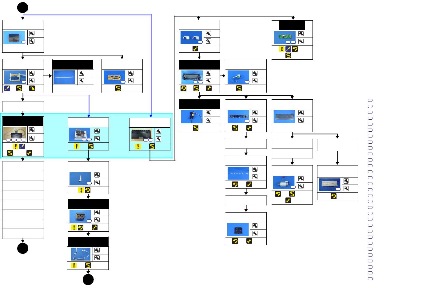
1.2.1.2 Printer Mechanism Part
1 |
(p 15) |
|
|
|
|
|
|
|
|
|
|
|
|
|
|
|
Wireless LAN |
CR Scale |
APG Assy |
|
Wireless LAN |
|
Wireless LAN |
|
APG Motor |
|
PF Encoder Assy |
|
ASF Relay |
|
ASF PE |
||
Module Assy |
|
Module Assy |
|
Module |
|
|
|
Board |
|
Sensor Assy |
||||||
|
|
|
|
|
|
|
||||||||||
|
|
--- |
|
3 |
|
|
3 |
|
3 |
|
2 |
|
1 |
|
1 |
--- |
|
|
3 |
S21 |
--- |
S6 |
S20 |
--- |
S12 |
2 |
S29 |
--- |
S23 |
4 |
S12 |
--- |
4 |
|
|
|
|
|
|
|
|
|
|
|||||||
(p 20) |
(p 20) |
(p 29) |
(p 31) |
(p 20) |
--- |
(p 31) |
(p 27) |
(p 29) |
(p 29) |
(p 30) |
2
(p 17)
|
|
|
|
|
|
|
|
|
|
|
|
|
|
|
|
|
|
|
|
|
|
Printer |
Driven Pulley |
|
PF Motor |
Board Assy (Main |
Roll Paper |
|
|
|
|||||||||||||
|
Ink Tube Holder |
||||||||||||||||||||
Mechanism* |
|
Board/Power |
Guide Assy |
||||||||||||||||||
|
|
|
|
|
|
|
|||||||||||||||
|
|
|
|
|
|
|
|
|
|
|
Supply Board) |
|
|
|
|
|
|
|
|
||
|
|
|
|
|
|
|
|
|
|
|
|
|
|
|
|
|
|
|
|||
|
6 |
A |
--- |
|
2 |
|
7 |
|
--- |
|
--- |
|
|
|
|
|
|
|
|
|
|
||
S13 S24 |
2 |
(p 18) |
--- |
S28 |
--- |
|
--- |
|
2 |
|
6 |
|
|
|
|
S20 |
S24 S30 |
|
|
|
|
||
(p 21) |
(p 21) |
(p 73) |
|
(p 29) |
(p 31) |
(p 27) |
(p 28, p 29) |
|
(p 20) |
|
|
|
|
|
|
|
|
(p 29) |
|
|
|
|
|
Lower Housing |
The Printer Mechanism in this flowchart is not the one established as an ASP. The Printer Mechanism as an ASP excludes the |
Main Board |
|
Power Supply |
|
||||||
Assy |
*: |
|
Board |
|
|||||||
|
following parts from the Printer Mechanism in this flowchart. When replacing the Printer Mechanism specified as an ASP, adjustments |
|
|
|
|||||||
|
|
|
|
|
|
||||||
|
--- |
are required. See Chapter 2 " Adjustment (p31)" for details. |
|
|
|
|
|
4 |
|
4 |
|
|
--- |
• ASF Assy |
|
• CR Support Plate |
|
|
S20 |
S31 |
--- |
S20 |
--- |
|
• LD Roller Guide |
|
• CR Cover |
|
|
||||||
|
|
|
|
|
|
|
|||||
(p 21) |
(p 28) |
• Board Assy (Main Board/Power Supply Board) |
|
• Ink Supply Unit |
|
|
|
(p 31) |
|
(p 31) |
|
• Head FFC |
|
• Ink Tube Holder |
|
|
|
|
|
||||
|
|
|
|
|
|
|
|
|
|
||
|
|
• Printhead |
|
• Paper Guide (under ASF Assy) |
|
|
|
|
|
|
|
|
|
• Printhead Mounting Plate |
|
• Shield Plate Assy Upper Main Board |
|
|
|
|
|
|
|
Waste Ink Pad |
Lower Paper |
Stacker Assy |
|
Foot |
Stacker Cover |
||
Guide Ink Pad |
|
||||||
|
|
|
|
|
|
||
|
|
Tray |
|
|
|
|
|
|
--- |
|
1 |
|
4 |
|
--- |
|
|
|
|
|
|
|
|
|
--- |
|
--- |
S6 |
--- |
|
--- |
|
|
S12 |
|
|
|
|
|
(p 20) |
(p 31) |
(p 31) |
(p 19) |
|
--- |
|
|
|
|
|
|
|
|
||
Waste Ink Tube |
Decomp Pump |
|
|
|
|
||
Assy |
|
|
|
|
|
||
|
|
|
|
|
|
|
|
|
1 |
|
3 |
|
|
|
|
S12 |
--- |
S6 |
--- |
|
|
|
|
(p 20) |
(p 73) |
(p 20) |
(p 28, p 29) |
|
|
|
|
Lower Housing |
|
|
|
|
|
|
|
|
--- |
|
|
|
|
|
|
|
--- |
|
|
|
|
|
|
--- |
|
|
|
|
|
|
|
Screw type/torque list
Symbol |
Screw type |
Torque |
|
|
|
S1 |
C.B.P-TITE SCREW,2.5X8,F/ZN-3C |
2.5 ± 0.5 kgf·cm |
S2 |
C.B.P-TITE SCREW,2.5X8,F/ZN-3C |
3.5 ± 0.5 kgf·cm |
S3 |
C.B.P-TITE SCREW,2X6,F/ZN-3C |
2.0 ± 0.5 kgf·cm |
S4 |
C.B.P-TITE SCREW,2X6,F/ZN-3C |
3.0 ± 1.0 kgf·cm |
S5 |
C.B.P-TITE SCREW,3X10,F/ZB-3C |
6.0 ± 1.0 kgf·cm |
S6 |
C.B.P-TITE SCREW,3X10,F/ZN-3C |
6.0 ± 1.0 kgf·cm |
S7 |
C.B.P-TITE SCREW,3X18,F/ZN-3C |
6.0 ± 1.0 kgf·cm |
S8 |
C.B.P-TITE SCREW,3X6,F/ZN-3C |
4.0 ± 0.5 kgf·cm |
S9 |
C.B.P-TITE SCREW,3X8,F/ZB-3C |
6.0 ± 1.0 kgf·cm |
S10 |
C.B.P-TITE SCREW,3X8,F/ZN-3C |
4.0 ± 0.5 kgf·cm |
S11 |
C.B.P-TITE SCREW,3X8,F/ZN-3C |
5.0 ± 1.0 kgf·cm |
S12 |
C.B.P-TITE SCREW,3X8,F/ZN-3C |
6.0 ± 1.0 kgf·cm |
S13 |
C.B.P-TITE SCREW,4X8,F/ZN-3C |
8.0 ± 1.0 kgf·cm |
S14 |
C.B.SCREW,2.5X14,F/ZN-3C |
3.0 ± 1.0 kgf·cm |
S15 |
C.B.SCREW,2.5X6,F/ZN-3C |
3.5 ± 0.5 kgf·cm |
S16 |
C.B.SCREW,3X4,F/ZN-3C |
4.0 ± 0.5 kgf·cm |
S17 |
C.B.SCREW,3X6,F/ZN-3C |
8.0 ± 1.0 kgf·cm |
S18 |
C.B.S-TITE SCREW,2.5X6,F/ZN-3C |
4.0 ± 0.5 kgf·cm |
S19 |
C.B.S-TITE SCREW,3X4,F/ZN-3C |
8.0 ± 1.0 kgf·cm |
S20 |
C.B.S-TITE SCREW,3X6,F/ZN-3C |
6.0 ± 1.0 kgf·cm |
S21 |
C.B.S-TITE SCREW,3X6,F/ZN-3C |
8.0 ± 1.0 kgf·cm |
S22 |
C.B.S-TITE SCREW,3X6,F/ZN-3C |
9.0 ± 1.0 kgf·cm |
S23 |
C.B.S-TITE SCREW,3X8,F/ZN-3C |
8.0 ± 1.0 kgf·cm |
S24 |
C.B.S-TITE(P2)SCREW,3X10,F/ZN-3C |
6.0 ± 1.0 kgf·cm |
S25 |
C.B.S-TITE(P4)SCREW,3X6,F/ZN-3C |
8.0 ± 1.0 kgf·cm |
S26 |
C.B.S-TITE(P4)SCREW,3X8,F/ZN-3C |
5.0 ± 1.0 kgf·cm |
S27 |
C.B.S-TITE(P4)SCREW,3X8,F/ZN-3C |
8.0 ± 1.0 kgf·cm |
S28 |
C.C.SCREW,3X4,F/ZN-3C |
4.0 ± 0.5 kgf·cm |
S29 |
C.P.SCREW,2.6X3,F/ZN-3C |
3.0 ± 0.5 kgf·cm |
S30 |
C.P.SCREW,3X10,F/ZN-3C |
6.0 ± 1.0 kgf·cm |
S31 |
C.P.SCREW,3X4,F/ZN-3C |
6.0 ± 1.0 kgf·cm |
Flowchart 1-2. Disassembly Flowchart of Printer Mechanism Part (1)
Disassembly/Reassembly |
Disassembly/Reassembly Flowchart |
16 |
SE Group Confidential (Related Staff Only)
SC-P600 |
Revision D |
2 (p 16)
|
|
|
|
|
|
|
|
|
|
|
|
|
|
|
|
|
|
CR Contact |
|
||
CR Cover |
|
LD Roller Guide |
|
|
|
|||||
|
|
|
Module |
|
||||||
|
|
|
|
|
|
|
|
|||
|
|
|
|
|
|
|
|
|
|
|
|
1 |
|
2 |
|
|
13 |
S20 |
2 |
S17 |
4 |
S7 |
S21 |
9 |
|
--- |
|
|
|
|
|
|
|
(p 31) |
|
|
|
|
|
(p 22) |
|
|
|
|
|
|
|
|
|
|
|
|
|
|
|
|
(p 29) |
|
|
|
CR Support |
|
Ink Tube Guide |
|
CR Relay Board |
|
|
ASF Assy |
|
ASF Motor |
|
|
|
|
|
|||
|
Plate |
|
|
|
|
|
|
|
|
|
|
||||||
|
|
|
|
|
|
|
|
|
|
|
|
|
|
|
|
|
|
|
|
4 |
--- |
|
|
2 |
|
|
|
4 |
|
|
2 |
|
|
|
|
|
S12 |
7 |
3 |
|
S20 |
--- |
|
S21 |
S27 |
2 |
S12 |
|
--- |
|
|
|
|
(p 21) |
(p 28) |
(p 73) |
--- |
|
(p 28) |
|
|
(p 24) |
(p 29) |
(p 31) |
(p 28, p 29) |
|
|
|
|
|
|
Wireless LAN |
|
|
|
|
|
|
PE Detector Assy |
|
Release Holder |
|
Paper Guide |
|
|
||||
|
|
|
|
|
|
|
Assy |
|
|
(under ASF Assy) |
|
|
|||||
Module Assy |
|
|
|
|
|
|
|
|
|
|
|
|
|
||||
|
|
|
|
|
|
|
|
|
|
|
|
|
|
|
|
||
|
|
|
|
|
|
|
|
|
|
--- |
|
|
3 |
|
--- |
|
|
Ink Supply Unit |
Ink Selector* |
|
I/C Holder Unit* |
|
|
4 |
S21 |
|
3 |
|
2 |
|
|
||||
|
|
|
|
|
|
|
|
|
|
||||||||
|
|
5 |
|
|
2 |
|
|
3 |
(p 28) |
|
(p 28) |
(p 31) |
|
--- |
|
|
|
|
|
|
|
|
|
|
|
|
|
|
|
|
|
|
|||
|
|
|
|
|
|
|
|
|
|
|
|
|
|
|
|
||
S1 S15 |
S21 S23 |
--- |
S1 S15 |
|
--- |
S21 |
S23 |
--- |
|
|
|
|
|
|
|
Board Assy (Main |
|
|
|
|
|
|
|
|
APG Assy |
|
APG Assy |
|
|||||||
|
|
|
|
|
|
|
|
|
|
|
|
Board/Power |
|
||||
|
(p 22) |
|
(p 11) |
(, p 28) |
|
(p 11) |
(, p 29) |
|
|
|
|
|
|
|
|
|
|
|
|
|
|
|
|
|
|
|
|
|
Supply Board) |
|
|||||
(, p 29, p 29) |
(p 31) |
|
|
|
|
|
|
|
|
|
|
|
Driven Pulley |
|
|
||
|
|
|
|
|
|
|
|
|
|
|
Release Flag |
|
|
|
|
|
|
Printhead |
|
Printhead |
|
|
|
|
|
|
Assy |
|
|
|
|
|
|
||
|
|
|
|
|
|
|
|
|
|
|
|
|
|
||||
Mounting Plate |
Mounting Plate |
|
|
|
|
|
|
|
|
--- |
CR Motor |
Shield Plate Assy |
|
||||
|
|
|
|
|
|
|
|
|
|
|
|
|
Upper Main |
|
|||
|
|
|
|
|
|
|
|
|
|
|
|
|
|
|
|
|
|
Print head |
|
|
|
1 |
|
|
|
|
|
|
|
4 |
|
2 |
Board |
|
|
|
|
|
|
|
|
|
|
|
|
|
|
|
|
|
|
||
|
|
|
|
|
|
|
|
|
|
|
|
|
|
|
|
3 |
|
|
|
|
S2 |
|
--- |
|
|
|
|
|
|
|
|
|
|
|
|
Head FFC |
|
|
|
|
|
|
|
(p 23) |
(p 31) |
|
|
--- |
|
|
|||
|
|
|
|
|
|
|
|
|
|
S16 |
|
2 |
|||||
|
|
|
|
|
|
|
|
|
|
|
|
|
|
S21 |
|||
|
|
|
|
(p 21) |
|
|
|
|
|
|
|
|
|
|
|
||
|
|
|
|
|
|
|
|
|
|
|
|
|
|
|
|
|
|
|
CR Scale |
|
|
|
|
|
|
|
|
|
|
|
|
(p 23) |
(p 28, p 29) |
(p 27) |
|
|
|
|
|
|
|
|
|
|
|
|
PE Detector Assy |
|
|
|
|
||
LD Roller Guide |
Print head |
|
|
|
|
|
|
|
(p 31) |
|
|
||||||
|
|
|
|
|
|
|
|
|
|
|
|
|
|||||
ASF Assy |
|
|
|
3 |
|
|
|
|
|
Upper Paper |
|
|
|
|
|
||
|
|
|
|
|
|
|
|
|
|
|
|
|
|
||||
|
|
|
|
|
|
|
|
|
|
|
|
|
|
|
|
||
Lower Housing |
S2 |
|
--- |
|
|
|
|
|
Guide Assy |
|
|
|
|
|
|||
|
|
|
|
|
|
|
|
|
|
|
|
|
|||||
|
|
|
|
|
|
|
|
|
|
|
|
|
|
||||
|
Assy |
|
(p 21) |
(p 31) |
|
|
|
|
|
|
|
--- |
|
|
|
|
|
Lower Paper |
|
|
|
|
|
|
|
|
|
|
|
|
|
||||
|
|
|
|
|
|
|
|
|
|
|
2 |
|
|
|
|
||
|
Guide |
|
|
|
|
|
|
|
|
|
|
|
|
|
|
|
|
|
|
|
|
|
|
|
|
|
|
|
|
|
|
|
|
|
|
|
|
|
Head FFC |
|
|
|
|
|
|
(p 23) |
(p 31) |
|
|
|
|
|
|
|
4 |
|
|
|
--- |
|
|
|
|
|
|
|
|
|
|
|
|
|
|
|
|
|
|
|
|
|
|
|
|
|
|
|
|
|
|
|
(p 18) |
|
|
|
--- |
|
|
|
|
|
|
|
|
|
|
|
|
|
|
|
(p 26) |
(p 28, p 29) |
|
|
|
|
|
|
|
|
|
|
|
|
|
|
|
|
|
|
|
|
|
|
|
*: The Ink Selector and I/C Holder Unit are the parts of the Ink Supply Unit. However, if the disassembly is |
|||||||
|
|
|
3 |
|
|
|
|
|
|
|
not for replacement of the Ink Supply Unit, it is faster that only either of the Ink Selector or I/C Holder |
||||||
|
|
|
|
|
|
|
|
|
|
Unit is removed to proceed the next step. Therefore, they are listed in this flowchart separately. |
|
||||||
|
|
|
|
|
|
|
|
|
|
|
|
||||||
|
|
|
(p 18) |
|
|
|
Flowchart 1-3. Disassembly Flowchart of Printer Mechanism Part (2) |
|
|
||||||||
Screw type/torque list
Symbol |
Screw type |
Torque |
|
|
|
S1 |
C.B.P-TITE SCREW,2.5X8,F/ZN-3C |
2.5 ± 0.5 kgf·cm |
S2 |
C.B.P-TITE SCREW,2.5X8,F/ZN-3C |
3.5 ± 0.5 kgf·cm |
S3 |
C.B.P-TITE SCREW,2X6,F/ZN-3C |
2.0 ± 0.5 kgf·cm |
S4 |
C.B.P-TITE SCREW,2X6,F/ZN-3C |
3.0 ± 1.0 kgf·cm |
S5 |
C.B.P-TITE SCREW,3X10,F/ZB-3C |
6.0 ± 1.0 kgf·cm |
S6 |
C.B.P-TITE SCREW,3X10,F/ZN-3C |
6.0 ± 1.0 kgf·cm |
S7 |
C.B.P-TITE SCREW,3X18,F/ZN-3C |
6.0 ± 1.0 kgf·cm |
S8 |
C.B.P-TITE SCREW,3X6,F/ZN-3C |
4.0 ± 0.5 kgf·cm |
S9 |
C.B.P-TITE SCREW,3X8,F/ZB-3C |
6.0 ± 1.0 kgf·cm |
S10 |
C.B.P-TITE SCREW,3X8,F/ZN-3C |
4.0 ± 0.5 kgf·cm |
S11 |
C.B.P-TITE SCREW,3X8,F/ZN-3C |
5.0 ± 1.0 kgf·cm |
S12 |
C.B.P-TITE SCREW,3X8,F/ZN-3C |
6.0 ± 1.0 kgf·cm |
S13 |
C.B.P-TITE SCREW,4X8,F/ZN-3C |
8.0 ± 1.0 kgf·cm |
S14 |
C.B.SCREW,2.5X14,F/ZN-3C |
3.0 ± 1.0 kgf·cm |
S15 |
C.B.SCREW,2.5X6,F/ZN-3C |
3.5 ± 0.5 kgf·cm |
S16 |
C.B.SCREW,3X4,F/ZN-3C |
4.0 ± 0.5 kgf·cm |
S17 |
C.B.SCREW,3X6,F/ZN-3C |
8.0 ± 1.0 kgf·cm |
S18 |
C.B.S-TITE SCREW,2.5X6,F/ZN-3C |
4.0 ± 0.5 kgf·cm |
S19 |
C.B.S-TITE SCREW,3X4,F/ZN-3C |
8.0 ± 1.0 kgf·cm |
S20 |
C.B.S-TITE SCREW,3X6,F/ZN-3C |
6.0 ± 1.0 kgf·cm |
S21 |
C.B.S-TITE SCREW,3X6,F/ZN-3C |
8.0 ± 1.0 kgf·cm |
S22 |
C.B.S-TITE SCREW,3X6,F/ZN-3C |
9.0 ± 1.0 kgf·cm |
S23 |
C.B.S-TITE SCREW,3X8,F/ZN-3C |
8.0 ± 1.0 kgf·cm |
S24 |
C.B.S-TITE(P2)SCREW,3X10,F/ZN-3C |
6.0 ± 1.0 kgf·cm |
S25 |
C.B.S-TITE(P4)SCREW,3X6,F/ZN-3C |
8.0 ± 1.0 kgf·cm |
S26 |
C.B.S-TITE(P4)SCREW,3X8,F/ZN-3C |
5.0 ± 1.0 kgf·cm |
S27 |
C.B.S-TITE(P4)SCREW,3X8,F/ZN-3C |
8.0 ± 1.0 kgf·cm |
S28 |
C.C.SCREW,3X4,F/ZN-3C |
4.0 ± 0.5 kgf·cm |
S29 |
C.P.SCREW,2.6X3,F/ZN-3C |
3.0 ± 0.5 kgf·cm |
S30 |
C.P.SCREW,3X10,F/ZN-3C |
6.0 ± 1.0 kgf·cm |
S31 |
C.P.SCREW,3X4,F/ZN-3C |
6.0 ± 1.0 kgf·cm |
Disassembly/Reassembly |
Disassembly/Reassembly Flowchart |
17 |
SE Group Confidential (Related Staff Only)
SC-P600 |
Revision D |
A (p 16)
CR Cover
CR Support
Plate
Ink Supply Unit
Middle Frame
6
S21 10
 (p 23)
Lower Paper
Guide
|
1 |
S27 |
3 |
--- |
|
Mist Board Assy |
|
Mist Board |
|
Stopper Tray |
Tray Detector |
||
|
|
Unit |
|
||||
|
|
|
|
|
|
|
|
|
1 |
|
3 |
|
2 |
|
--- |
S21 |
1 |
S22 |
--- |
S10 S21 |
--- |
|
4 |
(p 30) |
|
(p 31) |
|
|
(p 25) |
(p 29) |
(p 31) |
|
|
|
|
(p 31) |
(p 73) |
|
|
LD Roller Guide |
|
|
|
|
|
|
|
|
|
|
|
Star Wheel Assy |
|
|
|
ASF Assy |
|
|
|
Lower Paper |
|
|
|
|
|
|
|
|
|
||
Paper Guide |
|
|
|
Guide |
|
|
|
|
|
|
|
|
|
|
|
(under ASF Assy) |
|
|
|
|
|
|
|
|
|
|
|
Front Tray Assy |
|
|
|
Mist Board |
|
Ink System |
|
|
|
|
|
Cable Holder |
|
|
|
3 |
|
|
|
|
|
|
|
|
|
||
|
--- |
|
4 |
S8 |
--- |
|
|
|
2 |
S21 |
2 |
|
(p 25) |
|
|
|
|
|
|
|
|
||
(p 30) |
|
(p 24) |
(p 29) |
(p 31) |
(p 74) |
|
|
|
|
|
|
|
|
Tray Support |
|
|
|
|
|
|
|
Assy |
|
Lower Paper |
Star Wheel Assy |
--- |
|
Guide |
|||
|
|
||
|
|
--- |
Stopper Tray |
Front Paper |
Porous Pad |
(p 25) |
|
(p 31) |
|
Unit |
Guide Assy |
Front Paper |
|
|
|
|
|
|
|
Guide |
|
|
|
|
|
|
1 |
|
|
|
|
|
|
--- |
Front Tray |
||
Lower Frame |
S11 |
|
--- |
|
|
|
|
|
|
--- |
|
|
--- |
|
|
(p 26) |
|
|
|
|
|
4 |
(p 26) |
|
|
|
|
|
|
|
|
--- |
||
|
|
|
|
|
||
|
(p 31) |
(p 75) |
|
|
|
|
|
|
|
|
|
||
S21 |
2 |
|
|
|
|
|
|
|
|
|
(p 25) |
(p 31) |
(p 74) |
--- |
|
|
|
|
|
|
Star Wheel Assy
---
2
 (p 26)
  (p 31)
  (p 73)
|
3 (p 17) |
|
4 (p 17) |
||
|
|
|
|
|
|
|
|
|
|
|
|
APG Assy
Driven Pulley
CR Scale
I/C Holder Unit
Middle Frame
CR Guide Plate
5
S18 S25 |
--- |
 (p 21)
  (p 74)
CR Unit
---
---


 (p 24)
  (p 31)
  (p 74)
APG Assy
Driven Pulley
Middle Frame
CR Guide Plate
CR Unit
Mist Board Assy
Mist Board
Cable Holder
Paper Guide
(under ASF
Assy)
Stopper Tray
Unit
Lower Frame
Ink System
Star Wheel Assy
Front Paper
Guide Assy
Release Holder
Assy
Release Flag
Assy
PE Detector Assy
Upper Paper
Guide Assy
PF Frame
6
S19 |
--- |
 (p 23)
  (p 31)
Rear Paper
Guide
---
3
 (p 23)
  (p 31)
  (p 73)
PF Roller
---
---
(p 27)
 (p 31)
  (p 73)
Screw type/torque list
Symbol |
Screw type |
Torque |
|
|
|
S1 |
C.B.P-TITE SCREW,2.5X8,F/ZN-3C |
2.5 ± 0.5 kgf·cm |
S2 |
C.B.P-TITE SCREW,2.5X8,F/ZN-3C |
3.5 ± 0.5 kgf·cm |
S3 |
C.B.P-TITE SCREW,2X6,F/ZN-3C |
2.0 ± 0.5 kgf·cm |
S4 |
C.B.P-TITE SCREW,2X6,F/ZN-3C |
3.0 ± 1.0 kgf·cm |
S5 |
C.B.P-TITE SCREW,3X10,F/ZB-3C |
6.0 ± 1.0 kgf·cm |
S6 |
C.B.P-TITE SCREW,3X10,F/ZN-3C |
6.0 ± 1.0 kgf·cm |
S7 |
C.B.P-TITE SCREW,3X18,F/ZN-3C |
6.0 ± 1.0 kgf·cm |
S8 |
C.B.P-TITE SCREW,3X6,F/ZN-3C |
4.0 ± 0.5 kgf·cm |
S9 |
C.B.P-TITE SCREW,3X8,F/ZB-3C |
6.0 ± 1.0 kgf·cm |
S10 |
C.B.P-TITE SCREW,3X8,F/ZN-3C |
4.0 ± 0.5 kgf·cm |
S11 |
C.B.P-TITE SCREW,3X8,F/ZN-3C |
5.0 ± 1.0 kgf·cm |
S12 |
C.B.P-TITE SCREW,3X8,F/ZN-3C |
6.0 ± 1.0 kgf·cm |
S13 |
C.B.P-TITE SCREW,4X8,F/ZN-3C |
8.0 ± 1.0 kgf·cm |
S14 |
C.B.SCREW,2.5X14,F/ZN-3C |
3.0 ± 1.0 kgf·cm |
S15 |
C.B.SCREW,2.5X6,F/ZN-3C |
3.5 ± 0.5 kgf·cm |
S16 |
C.B.SCREW,3X4,F/ZN-3C |
4.0 ± 0.5 kgf·cm |
S17 |
C.B.SCREW,3X6,F/ZN-3C |
8.0 ± 1.0 kgf·cm |
S18 |
C.B.S-TITE SCREW,2.5X6,F/ZN-3C |
4.0 ± 0.5 kgf·cm |
S19 |
C.B.S-TITE SCREW,3X4,F/ZN-3C |
8.0 ± 1.0 kgf·cm |
S20 |
C.B.S-TITE SCREW,3X6,F/ZN-3C |
6.0 ± 1.0 kgf·cm |
S21 |
C.B.S-TITE SCREW,3X6,F/ZN-3C |
8.0 ± 1.0 kgf·cm |
S22 |
C.B.S-TITE SCREW,3X6,F/ZN-3C |
9.0 ± 1.0 kgf·cm |
S23 |
C.B.S-TITE SCREW,3X8,F/ZN-3C |
8.0 ± 1.0 kgf·cm |
S24 |
C.B.S-TITE(P2)SCREW,3X10,F/ZN-3C |
6.0 ± 1.0 kgf·cm |
S25 |
C.B.S-TITE(P4)SCREW,3X6,F/ZN-3C |
8.0 ± 1.0 kgf·cm |
S26 |
C.B.S-TITE(P4)SCREW,3X8,F/ZN-3C |
5.0 ± 1.0 kgf·cm |
S27 |
C.B.S-TITE(P4)SCREW,3X8,F/ZN-3C |
8.0 ± 1.0 kgf·cm |
S28 |
C.C.SCREW,3X4,F/ZN-3C |
4.0 ± 0.5 kgf·cm |
S29 |
C.P.SCREW,2.6X3,F/ZN-3C |
3.0 ± 0.5 kgf·cm |
S30 |
C.P.SCREW,3X10,F/ZN-3C |
6.0 ± 1.0 kgf·cm |
S31 |
C.P.SCREW,3X4,F/ZN-3C |
6.0 ± 1.0 kgf·cm |
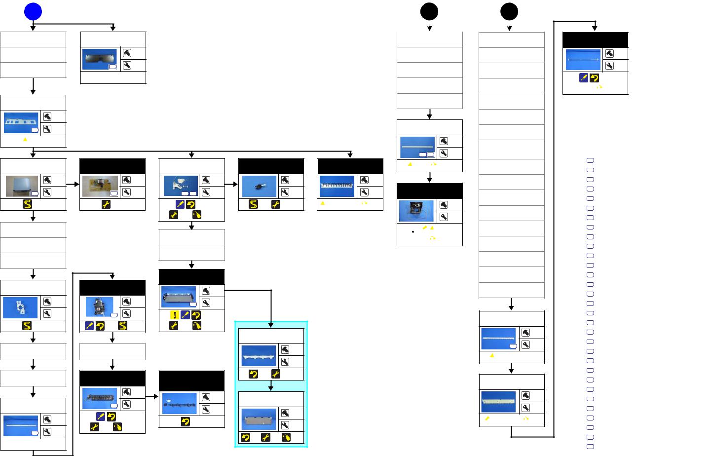
Flowchart 1-4. Disassembly Flowchart of Printer Mechanism Part (3)
Disassembly/Reassembly |
Disassembly/Reassembly Flowchart |
18 |
SE Group Confidential (Related Staff Only)

SC-P600 Revision D
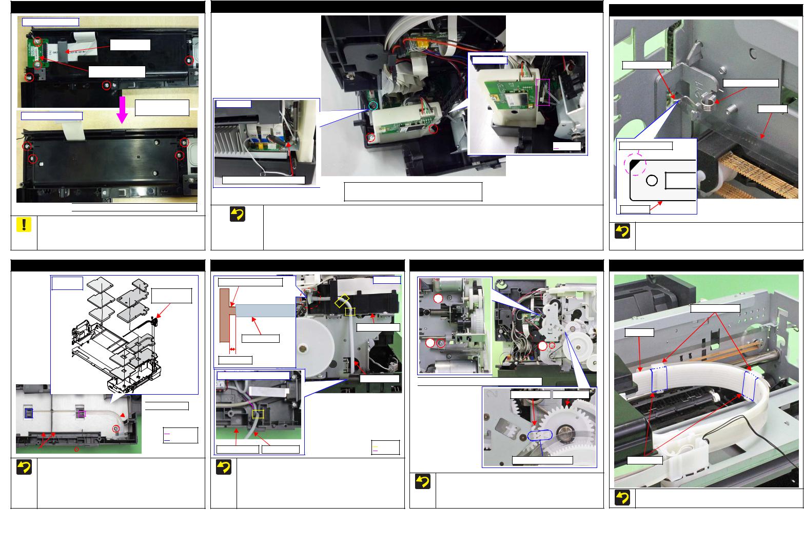
1.3 Detailed Disassembly/Reassembly Procedure for each Part/Unit
|
|
Rear Housing |
|
|
|
Left / Right Cover |
|
|
|
Left / Right Decoration Plate |
|
|
|
Stacker Assy |
||||||||
|
|
|
|
|
|
|
|
|
|
|
|
|
|
|
|
|
|
|
|
|
|
|
|
|
|
|
|
Left |
|
|
|
|
|
|
|
|
|
|
|
|
|
|
|
|
|
|
Rear |
|
|
|
|
|
|
|
|
|
Left Decoration Plate |
|
|
|
|
|
|
|
|
|
|
|
|
|
|
|
|
|
|
|
|
|
|
|
|
|
|
|
|
|
|
|
|
|
|
|
|
|
|
|
|
|
|
|
|
|
|
|
|
|
|
|
|
|
|
|
|
|
|
|
|
|
|
|
|
|
|
|
|
|
Right Decoration Plate |
|
|
|
|
|
Stacker Assy |
|
|||
|
|
|
|
|
|
|
Left Cover |
|
|
|
|
|
|
|
|
|
|
|
|
|
|
|
|
|
|
|
|
|
|
|
|
|
|
|
|
|
|
|
|
|
|
|
|
|
|
|
|
|
|
|
|
|
|
|
|
|
|
|
|
|
|
|
Bottom |
|
|
|
|
|
|
|
|
|
|
|
|
|
|
|
|
|
|
|
|
|
|
||||||
|
Rear Housing |
Right |
|
|
|
Back of Rear Housing |
|
|
Left |
Right |
|
Left |
Right |
|
|
|
|
|
|
Right Cover |
|
|
|
|
|
Hook |
|
|
|
|
|
Rib |
|
|
|
|
Hook |
Section A |
|
|
Lower Housing Assy |
|
Dowel |
C.B.P-TITE SCREW,3X10,F/ZB-3C (6 ± 1 kgf·cm) |
|
|
|
|
Rib |
|
|
C.B.P-TITE SCREW,3X10,F/ZN-3C (6 ± 1 |
|
|
C.B.P-TITE SCREW,3X8,F/ZB-3C (6 ± 1 kgf·cm) |
|
|
|
|
|
Remove the Left/Right Cover carefully not to damage the hooks |
|
|
Rib |
|
|
C.B.S-TITE SCREW,3X6,F/ZN-3C (6 ± 1 kgf·cm) |
|
Lower Housing |
||
|
(x2 each) and ribs (x3 each) that secure the Left/Right Cover. |
|
Hook |
||
|
|
|
|||
|
|
|
|
|
|
|
|
|
|
|
|
|
Be careful for ink to flow out then because if tilting is too soon after |
|
Be careful not to damage the hooks (x2), dowels (x2) and ribs (x8) |
|
When removing the Left/Right Cover, slide it in the direction of the |
|
|
Be careful not to damage the ribs (x3 each) that secure the Left/ |
the initial ink charge or a similar situation, the ink still on the Waste |
||
|
that secure the Rear Housing. |
|
arrow shown above while slightly pushing the section A. |
|
|
Right Decoration Plate and hooks (x4) of the Lower Housing. |
Ink Pad which is not yet absorbed flows over out of the printer. |
||
|
|
|
|
|
|
|
|
|
|
|
Upper Housing Support Assy (w/Panel Unit) |
|
|
Back of Upper Housing Support Assy |
|
|
Upper Housing Support Assy |
|
Left |
I/C Holder Unit |
Right |
|
Cover Open Sensor |
|
|
Cable |
|
|
Upper Housing |
|
|
Support Assy |
|
Panel FFCs
Panel SUBBoard |
Hook |
C.B.P-TITE SCREW,3X10,F/ZN-3C (6 ± 1 kgf·cm) |
Disconnect the Panel FFCs (x2) from the connectors on the Panel SUB Board before removing the Upper Housing Support Assy.
Be careful not to damage the hooks (x4) that secure the Upper Housing Support Assy.
Be careful to remove the Upper Housing Support Assy because the I/C Holder Unit Cover Open Sensor Cable is connected to the sensor on the back of the Upper Housing Support Assy.
Upper Housing Assy (w/Printer Cover Upper)
|
|
|
|
|
|
|
|
Rear left |
|
|
|
Rear right |
|
|
|
|
|
|
|
|
Upper Housing Assy
3 
4 
Left |
|
Right |
|
Hole |
Panel FFCs
2 
1 

 C.B.P-TITE SCREW,4X8,F/ZN-3C (8 ± 1 kgf·cm)
Pull out the Panel FFCs(x2) from the hole of the Upper Housing Assy before removing the Upper Housing Assy.
Tighten the screws in the order indicated in the figure above.
Disassembly/Reassembly |
Detailed Disassembly/Reassembly Procedure for each Part/Unit |
19 |
SE Group Confidential (Related Staff Only)
SC-P600 |
Revision D |
Panel Unit
Pane Cover Rear
Ferrite Core
Panel SUB Board
Remove the Panel
Cover Rear
Housing Panel Rear

 C.B.P-TITE SCREW,3X8,F/ZN-3C (6 ± 1 kgf·cm)
When disassembling the Panel Unit, take off the fixed screws (x4) of the shafts that of Housing Panel Rear. Then remove the unit from the Housing Upper Support Assy by turning the whole unit forward.
Wireless LAN Module Assy
Right side
Rear side |
Wireless LAN Module cable |


 Hook
Hook
 C.B.P-TITE SCREW,3X10,F/ZN-3C (6±1 kgf·cm)
 C.B.S-TITE SCREW,3X6,F/ZN-3C (6±1 kgf·cm)
When installing the Wireless LAN Module Assy, put the following four cables through a hook of the part right side.
•Printer Cover Open Sensor cable
•I/C Holder Unit Cover Open Sensor cable
•Mist Board cable
•ASF PE Sensor Cable
CR Scale
Longer spring leg
Torsion Spring, 0.39
CR Scale
Black triangle mark |
CR Scale |
Attach the CR Scale to the spring leg with the black triangle mark upward on the left side of the printer.
Attach the Torsion Spring, 0.39 as shown above.
Waste Ink Tube / Waste Ink Pad
Installation |
order |
Waste Ink Tube |
/ Tube Holder |
 Waste Ink Tube

 Section A

 Section B
Waste Ink Pads |
|
C.B.P-TITE SCREW,3X8,F/ZN-3C (6 ± 1 kgf·cm) |
When installing the Waste Ink Tube/Waste Ink Pads (x10), confirm the shapes of them and install them in the order shown above.
When installing the Waste Ink Tube, route it through the groove of the Waste Ink Pads, and insert the end of the shorter tube to the section A and longer one to the section B.
Decomp Pump Assy
Joint for Decomp Tube
Decomp Tube
1 mm or less |
|
Left inside of Lower Housing |
|
Lower Housing |
Decomp Tube |
Left side
I/C Holder Unit
Decomp Tube

 Hook
Hook
Groove
When connecting the Decomp Tube to the joint of the I/C Holder Unit, make sure the gap between the end of the Decomp Tube to the base of the joint is 1 mm or less, and then secure the tube with the hooks (x2).
Route the Decomp Tube through the groove of the Lower Housing and secure the tube with the hook.
APG Assy
1 

2 |
3 |
|

 C.B.S-TITE SCREW,3X6,F/ZN-3C(8 ± 1kgf·cm)
Spur Gear,14.4 
 PG Cam Left
Align triangle marks.
When installing the APG Assy, align the marks on the Spur Gear,14.4 and PG Cam Left to match their phases as shown above.
Tighten the screws in the order indicated in the figure above.
Ink Tube Holder
Ink Tube Holders
Ink Tube
Acetate Tape
When installing the Ink Tube Holders (x2), install them on the locations where the acetate tape (x2) is attached on the Ink Tube.
Disassembly/Reassembly |
Detailed Disassembly/Reassembly Procedure for each Part/Unit |
20 |
SE Group Confidential (Related Staff Only)
SC-P600 |
|
|
|
Revision D |
|
|
Printer Mechanism (1) |
|
Printer Mechanism (2) |
|
|
Rear left |
|
Upper left |
Right |
|
|
|
|
Printer Mechanism |
|
||
|
|
|
|
|
|
|
|
|
|
3 |
6 |
|
|
|
4 |
|
|
|
|
|
|
|
2 |
|
Decomp Pump Motor Cable |
|
|
|
|
Stopper Tray Sensor Relay Cable |
Rear left |
|
Tube Clamp |
|
|
Left |
Decomp Tube |
Right |
|
Ink System Tubes |
Tube Holder |
|
|
|
|
||
|
Lower Housing Assy |
Waste Ink Tube |
|
|
5 ± 2 mm |
|
|
|
|
||
|
|
5 |
|
|
|
I/C Holder |
Ink System Tube |
Front Left |
|
|
|
Unit |
|
|
|||
|
|
|
|||
|
Disconnect the following cables/tubes when removing the Printer Mechanism from the Lower Housing Assy. |
|
|
1 mm or less |
|
|
|
Tube Clamps |
|
||
|
Disconnect the following cables from the connector on the Main Board. |
C.B.P-TITE SCREW,4X8,F/ZN-3C |
1 |
Waste Ink Tubes |
|
|
(8 ± 1kgf·cm) |
|
|||
|
• Stopper Tray Sensor Relay Cable (CN1) |
C.B.S-TITE(P2)SCREW,3X10,F/ZN-3C |
|
|
|
|
• Decomp Pump Motor Cable (CN22) |
(6 ± 1kgf·cm) |
|
|
|
|
|
|
|
|
|
|
Disconnect the Decomp Tube. |
Tighten the screws in the order indicated in the figure above. |
|
|
|
|
Disconnect the Ink System Tube from the Waste Ink Tube. |
When connecting the Ink System Tube to the Waste Ink Tube, make sure the gap between the end of the Ink System Tube and the Tube Holder is |
|||
|
Disconnect the relay connector of the Stopper Tray Sensor Relay Cable. |
1 mm or less, and attach the Tube Clamp 5 ± 2 mm from the end of the Ink System Tube. |
|
|
|
|
|
|
|
|
|
|
CR Support Plate |
|
|
|
|
|||||
|
|
|
|
|
|
|
|
|
|
|
|
|
|
|
|
|
|
|
|
CR Encoder / PW Sensor FFC |
|
|
|
|
|
|
|
|
|
|
|||
|
|
|
|
|
|
|
|
|
|
|
|
|
|
|
|
|
|
|
|
|
|
|
|
|
|
|
|
|
|
|
|
|
|
|
|
|
CR Relay Board |
|
|
|
|
|
|
|
|
|
|
|
|
|
|
|
|
|
|
|
|
|
|
|
|
|
|
||||
|
|
|
|
|
|
|
|
|
|
Ink Tube Guide |
|
|
|
|
|
|
|
|
|
|
|
|
|
|
|
|
|
|
|
|
|
|
|
|
|
|
|
|
|
|
|
|
|
|
|
|
|
|
|
|
|
Ink Selector Motor Cable |
|
|
|
|
|
Head FFC |
|
|
|
Ink Tube Holder |
|
|
|||
|
Ink Selector Sensor Cable |
|
|
|
|
|
|
|
|
|
|
|
|
|
||
|
|
|
|
|
|
|
|
|
|
|
|
|
|
|||
|
|
|
|
|
|
|
|
|
|
|
|
|
|
|
|
|
Ink Tube Guide |
|
|
CR Support Plate |
Ink Tube Holders |
|
Cable Holder Front |
Ink Tube Guide |
|
|
|
|
Cable Holder Front |
|
Hook |
|
Rib |
|
|
|
|
|
|
Positioning hole |
|
C.B.P-TITE SCREW,3X8,F/ZN-3C (6 ± 1 kgf·cm) |
and Dowel |
When removing the CR Support Plate, follow the procedure below.
1. Disconnect the following cables/FFCs from the connectors on the CR Relay Board.
• |
Ink Selector Motor Cable (CN2) |
• |
Ink Selector Sensor Cable (CN5) |
• |
Head FFC (CN1) |
• |
CR Encoder / PW Sensor FFC (CN6) |
2.Remove the screws (x4) that secure the CR Support Plate.
3.Release the hooks (x3 each) of the Ink Tube Holders (x2) and remove the Ink Tube Guide from the Ink Tube Holders (x2).
4.Release the Ink Tube Guide from the ribs (x6) and dowel of the Cable Holder Front, and remove the CR Support Plate.
CR Guide Plate
CR Guide Plate
6 |
5 |
4 |
3 |
2 |
1 |
CR Unit
 C.B.S-TITE(P4)SCREW,3X6,F/ZN-3C(8 ± 1kgf·cm)
  C.B.S-TITE SCREW,2.5X6,F/ZN-3C(4 ±
Tighten the screws in the order indicated in the figure above.
Printhead / Printhead Mounting Plate
Printhead
1 
2 
3 |
|
Printhead Mounting Plate |
|
C.B.P-TITE SCREW,2.5X8,F/ZN-3C(3.5 ± 0.5kgf·cm) |
CR Unit |
Do not use the electric screwdriver when installing the Printhead and/or the Printhead Mounting Plate. Doing so applies extra force when tightening the screw and affects the platen gap.
When installing the Printhead, follow the procedure below.
1.Temporarily tighten the screws (x3) and loosen them half turn.
2.Press the Printhead to the rear of the printer, and tighten the screws (x3) in the order indicated in the figure above.
Disassembly/Reassembly |
Detailed Disassembly/Reassembly Procedure for each Part/Unit |
21 |
SE Group Confidential (Related Staff Only)
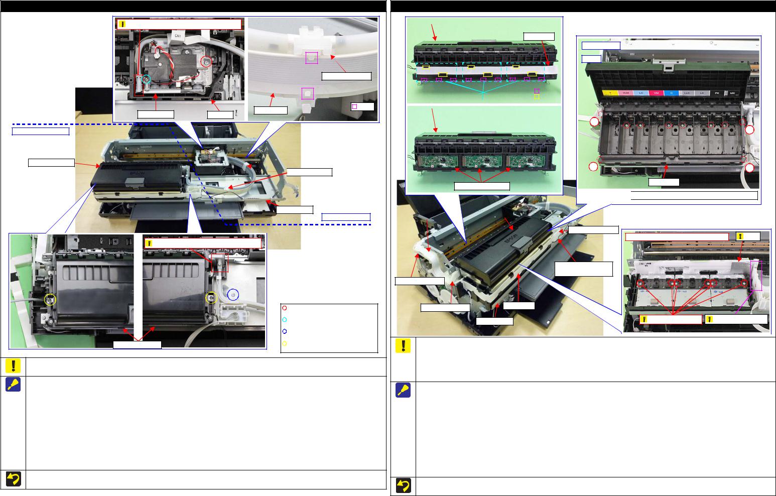
SC-P600 |
Revision D |
Ink Supply Unit
Ink tube connection part: Do not disassemble |
|
|
Ink Tube Holder |
|
Hook |
Ink Selector |
Head FFC |
CR Unit |
|
I/C Holder Unit side
I/C Holder Unit
 Ink Tube Holders
Middle Frame
Ink Selector side
Ink tube connection part: Do not disassemble |
I/C Holder Unit |
 C.B.P-TITE SCREW,2.5X8,F/ZN-3C (2.5 ± 0.5 kgf·cm)
 C.B.SCREW,2.5X6,F/ZN-3C (3.5 ± 0.5 kgf·cm)
 C.B.S-TITE SCREW,3X6,F/ZN-3C (8 ± 1 kgf·cm)
 C.B.S-TITE SCREW,3X8,F/ZN-3C (8 ± 1 kgf·cm)
To prevent ink leakage, make sure not to separate the ink tubes from the I/C Holder Unit or the Ink Selector by removing the screws (x2). Loosening the screws even just once will cause ink leakage, therefore, make sure to replace the Ink Supply Unit with a new one.
When removing the Ink Supply Unit, follow the procedure below.
1.Release the Head FFC from the hooks (x2 each) of the Ink Tube Holders (x2). Be careful not to damage the Head FFC then.
2.Remove the screws (x2) that secure the Ink Selector, and remove the Ink Selector from the CR Unit.
3.Disconnect the Decomp Tube from the I/C Holder Unit. (p 21)
4.After removing the Cable Holder Rear and Cable Holder Left from the frame, disconnect the Head FFC and CSIC FFC from the connectors on the Main Board, and then release the FFCs from the Cable Holder Rear and Cable Holder Left. (p 29)
5.Remove the screws (x3) that secure the I/C Holder Unit, and remove the I/C Holder Unit.
When removing the Ink Selector on the way to the target part, perform only Step 1 and 2 above. Be careful not to contaminate the surroundings with ink from the Ink Selector when taking subsequent steps.
When removing the I/C Holder Unit on the way to the target part, perform only Step 3 to 5 above. Place the removed I/C Holder Unit on the 0- digit side of the Middle Frame when taking subsequent steps.
Do not use the electric screwdriver when installing the Printhead. Doing so applies extra force when tightening the screw and affects the platen gap.
CR Contact Module
Ink Box |
|
Step 8, 9 |
CSIC FFC
Inside Ink Box
Step 7 |
|
|
|
|
|
Hook |
|
|
|
CR Contact Module Covers |
|
|
Rib |
|
|
|
|
|
|
|
|
|
|
|
|
|
|
|
Ink Box |
|
|
|
|
Step 9 |
|
|
|
|
|
|
|
|
3 
4 
2 |
1 |
Ink Box
CR Contact Modules

 C.B.P-TITE SCREW,3X18,F/ZN-3C (6 ±
CSIC FFC |
|
I/C Holder Unit |
|
|
Cable Holder Front |
|
|
|
|
Bottom part of Ink Box: Do not dissemble |
Film |
|
|
|
I/C Holder Unit Cover |
|
|
|
|
Open Sensor Cable |
|
|
Cable Holder Rear |
|
|
|
|
Cable Holder Left |
Head FFC |
|
|
|
|
|
|
|
|
|
Middle Frame |
Do not loosen screws |
Ink Tube connection |
|
|
|
|
|
|
To prevent ink leakage, make sure of the following when disassembling/reassembling the unit.
Do not remove the screws (x6) on the bottom of the Ink Box. Loosening the screws even just once will cause ink leakage, therefore, make sure to replace the Ink Supply Unit with a new one.
Be careful not to damage the film of the ink path.
Be careful not to apply extra force on the Ink Tube connection.
When removing the CR Contact Modules (x3), follow the procedure below.
1. Disconnect the Head FFC and CSIC FFC from the connectors on the Main Board, and remove the Cable Holder Rear and Cable Holder Left from the frame. (p 29)
2.Remove the Cable Holder Rear and Cable Holder Left from the CSIC FFC. (p 29)
3.Release the Head FFC from the ribs of the I/C Holder Unit. (p 28)
4.Release the I/C Holder Unit Cover Open Sensor Cable from the rib and hook of the Cable Holder Front. (p 28)
5.Remove the screws (x3) that secure the I/C Holder Unit. (p 22)
6.Remove the screws (x4) on the corners of the Ink Box and screws (x6) inside the Ink Box that secure the Ink Box.
7.Release the CSIC FFCs (x3) from the ribs (x6) of the Ink Box, and disconnect the CSIC FFCs (x3) from the connectors on the CR Contact Modules (x3).
8.Release the hooks (x3 each) of the CR Contact Module Covers, and remove the CR Contact Module Covers and CR Contact Modules.
Tighten the screws in the order indicated in the figure above when securing the screws (x4) on the corner of the Ink Box.
Disassembly/Reassembly |
Detailed Disassembly/Reassembly Procedure for each Part/Unit |
22 |
SE Group Confidential (Related Staff Only)
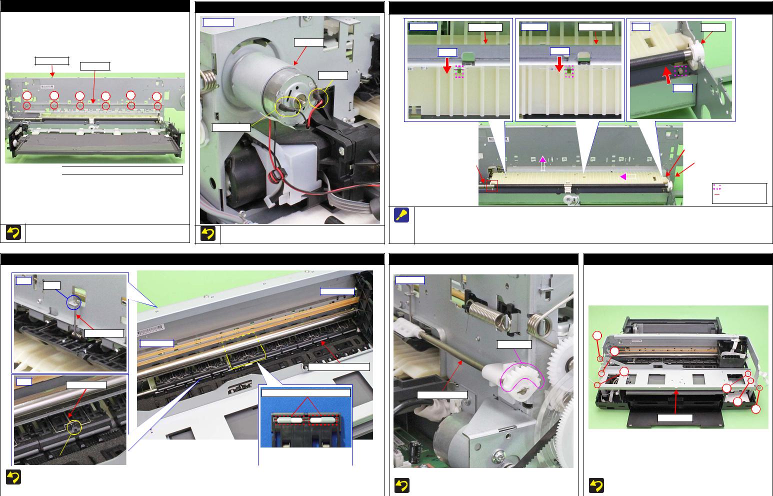
SC-P600 |
Revision D |
PF Frame
Main Frame
PF Frame
6 |
5 |
4 |
3 |
2 |
1 |

 C.B.S-TITE SCREW,3X4,F/ZN-3C(8 ± 1kgf·cm)
Tighten the screws in the order indicated in the figure above.
CR Motor
Rear right
CR Motor
Red Cable
Black Cable
When installing the CR Motor, attach it with its red cable to the left side of the printer.
Rear Paper Guide
Upper left |
Main Frame |
|
Step 1 |
Center |
Main Frame |
|
Step 1 |
Right |
Bush, 8 |
|
Step 1 |
|
|
|
|
|
|
|
|
|
|
|
Rear Paper Guide |
|
|
|
|
|
|
|
|
|
|
|
|
|
|
|
|
|
|
|
|
|
|
|
|
|
|
|
|
|
|
PF Roller |
|
Step 3 |
|
|
|
|
Step 2 |
|
|
Main Frame |
|
||
|
|
|
|
|
|
|
|
|
|||||
|
|
|
|
|
|
|
|
|
|
|
|
|
|
|
|
|
|
|
|
|
|
|
|
|
|
|
|
|
|
|
|
|
|
|
|
|
|
|
|
|
|
|
|
|
|
|
|
|
|
|
|
|
|
|
|


 Positioning dowel

 Engagement point with PF Roller
When removing the Rear Paper Guide, follow the procedure below.
1.Push the positioning dowels (x3) in the direction of the red arrow to release them.
2.Slide the Rear Paper Guide approx. 5 mm to the left to release the right side of the Rear Paper Guide from the Bush, 8.
3.Lift the rear side of the Rear Paper Guide and release it from the PF Roller, and then remove the Rear paper Guide.
Upper Paper Guide Assy |
|
Release Flag Assy |
Middle Frame |
Front |
|
Rear left |
|
Hook |
|
|
|
|
0-digit side |
|
|
Torsion spring |
|
|
2 |
|
|
|
|
130-digit side |
|
Gear Section |
|
|
|
|
4 |
|
Upper Paper Guide Assy |
|
6 |
|
|
|
|
Rear |
|
|
|
Torsion spring |
|
|
5 |
|
The rubber parts on roller are shorter. |
Release Flag Assy |
|
|
|
||
|
|
|
|
|
|
|
3 |
|
|
|
1 |
|
|
|
Middle Frame |
|
|
|
|
|
|
|
The fourth roller of Upper Paper |
|
|
|
|
|
|
|
|
|
|
|
Hole |
|
|
Guide Assy from the 0-digit side |
|
|
|
|
|
|
|
|
|
|
|
|
|
|
has shorter rubber parts. |
|
|
|
|
|
|
|
|
|
|
|
|
|
|
|
|
|
|
|
|
||
|
|
|
|
|
|
|
|
|
|
|
|
|
|
|
|
|
|
|
|
|
|
|
|
|
|
|
|
|
|
|
|
|
Make sure to install the Upper Paper Guide Assy whose roller has shorter rubber parts on the fourth position from 0-digit side. |
|
|
|
|
|
|
|||||
|
|
|
When attaching the torsion spring, insert the spring leg (straight side) into the hole of the Upper Paper Guide Assy, and engage the other leg to |
|
|
When installing the Release Flag Assy, install it with its gear |
|
|
Tighten the screws in the order indicated in the figure above. |
|||||
|
|
|
the hook of the frame. |
|
|
|
|
|
section upward. |
|
|
|
||
|
|
|
|
|
|
|
|
|
|
|
|
|
|
|
|
|
|
|
|
|
|
|
|
|
|
|
|
|
|
|
Disassembly/Reassembly |
|
Detailed Disassembly/Reassembly Procedure for each Part/Unit |
23 |
||||||||||
|
|
|
|
|
|
|
|
|
|
|
|
|
|
|
SE Group Confidential (Related Staff Only)
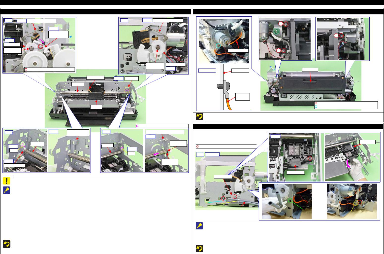
SC-P600 |
|
|
|
|
|
|
|
|
|
|
|
|
Revision D |
|
|
|
|
CR Unit |
|
|
|
|
|
|
|
|
ASF Assy |
Left |
Step 3 |
PG Torsion Spring Left |
|
|
Right |
Step 3 PG Torsion Spring Right |
|
|
|
1 |
|||
|
|
|
|
|
|
|
|
|
|
|
|
|
|
|
|
Step 4 |
|
|
|
|
|
|
|
|
|
|
|
|
|
Parallelism |
|
|
|
|
|
|
|
|
|
|
3 |
|
|
Adjust Bushing |
|
|
|
|
|
|
|
|
|
|
|
Step 8 |
|
|
|
|
|
|
|
|
|
|
|
|
|
PG Cam Left |
|
|
|
|
|
|
|
|
|
|
|
|
|
Washer, |
|
|
|
|
|
|
|
|
|
|
|
Grounding Wire |
2 |
6.9X0.5X10.4 |
|
|
|
|
|
|
|
|
|
|
|||
|
|
|
|
|
|
|
|
|
|
|
|
||
|
|
|
|
|
|
|
Washer, |
|
PG Cam Right |
|
|
|
|
|
|
C.B.S-TITE(P4) SCREW,3X10,F/ZN-3C |
|
|
|
6.9X0.5X10.4 |
Step 8 |
Cross-section |
|
ASF Assy |
|||
|
|
|
|
|
|
|
Main Frame |
||||||
|
|
|
|
|
|
|
|
||||||
|
|
|
|
Timing Belt |
Step 1 |
CR Motor |
|
|
|
|
|
|
|
|
|
|
CR Shaft |
|
|
|
|
|
|
|
|
|
|
|
|
|
|
|
|
|
|
|
|
|
|
Grounding |
|
|
|
|
|
|
|
|
|
|
|
|
|
wire |
|
|
|
|
|
|
|
|
|
|
|
|
|
|
C.B.S-TITE(P4)SCREW,3X8,F/ZN-3C(8 ± |
|
|
|
|
CR Unit |
|
|
|
|
|
|
|
|
C.B.S-TITE SCREW,3X6,F/ZN-3C(8 ± 1kgf·cm) |
|
|
|
|
|
|
|
|
|
|
|
Tighten the screws in the order indicated in the figure above. |
||
|
|
|
|
|
|
|
|
|
|
|
Attach the terminal of the grounding wire in the direction shown in the “Cross-section” figure. |
||
|
|
|
|
|
|
|
C.B.SCREW,3X4,F/ZN-3C (4 ± 0.5 kgf·cm) |
|
|
|
Ink System |
||
Left |
|
Step 7 |
Left CR Shaft |
Right |
|
|
Right CR Shaft Mounting Plate |
|
|
|
|
||
|
|
|
Mounting Plate |
|
|
|
Step 9 |
|
|
|
|
|
Step 3 |
|
|
|
|
|
|
|
|
|
|
|
|
||
|
|
CR Shaft |
|
|
|
|
|
|
Washer, |
|
|
|
Ink System |
Step 6 |
|
|
CR Shaft |
|
|
|
|
8.2X0.5X15 |
C.B.S-TITE SCREW,3X6,F/ZN-3C (8 ± 1 kgf·cm) |
|
|||
|
|
|
|
|
|
|
|
||||||
|
|
|
|
|
Step 6 |
|
|
|
|
||||
Dent |
|
|
|
|
|
|
|
|
|
|
|
|
|
|
|
|
|
|
Dent |
|
|
|
|
|
|
|
|
|
|
|
|
|
|
|
|
|
Right |
Step 1,3,4 |
|
|
|
|
|
|
|
|
|
|
|
|
|
|
|
||
Step 5 |
|
|
|
|
|
|
|
Leaf Spring, |
|
|
|
|
|
CR Shaft Spacer |
|
|
|
|
|
|
8.2X0.25X15 |
|
|
|
|
||
|
|
|
|
|
|
|
|
|
|
|
|
||
|
|
|
|
|
|
|
|
|
|
|
|
|
Ink System |
Support Plate
Be careful not to let the grease of the CR Shaft adhere to the Timing Belt of the CR Unit.
|
|
|
|
|
|
|
|
|
|
|
|
|
|
|
|
|
Step 2,4 |
|
|
When removing the CR Unit, follow the procedure below. |
|
|
|
|
|
|
|
|
|
|
|
|
|
|
|||||
|
|
|
|
|
|
|
|
|
|
|
|
|
|
|
|
|
|
||
|
|
|
|
|
|
|
|
|
|
|
|
|
|
|
|
|
|
||
1. |
Remove the screws (x2) that secure the CR Motor, and remove the CR Motor from the frame. |
|
|
|
|
|
|
|
|
|
|
|
|
|
|
|
|
|
|
2. |
Mark the contact point on the Parallelism Adjust Bushing with the frame. (p 50) |
|
|
|
|
|
|
|
|
|
|
|
|
|
|
|
|
|
|
|
|
|
|
|
|
|
|
|
|
|
|
|
|
|
|
|
|
||
3. |
Remove the PG Torsion Spring Left / Right. |
|
|
|
|
|
|
|
|
|
|
|
|
|
|
|
|
|
|
|
Hole |
|
|
|
|
|
|
|
|
|
|
|
|
|
|
|
|
||
4. |
Loosen the screw that secure the Parallelism Adjust Bushing, and turn the Parallelism Adjust Bushing in the direction of the arrow shown above. |
|
|
|
|
|
|
|
|
|
|
|
|
|
|
|
|
|
|
|
|
|
Clamp A |
|
|
|
|
|
|
|
|
|
|
|
|
|
|
||
5. |
Remove the CR Shaft Spacer. |
|
|
|
|
|
Ink System Tube |
|
|
|
|
|
|
||||||
|
|
|
|
|
|
|
|
||||||||||||
|
|
|
|
|
|
|
|
|
|
|
|
|
A hole to attach a clamp |
|
|
|
|
||
6. |
Lift the CR Shaft, and move both ends of it to the dent of the frame. |
|
|
|
|
|
|
|
|
|
|
|
|
|
to fix the Ink Tube |
|
|
|
Connector |
|
|
|
|
|
|
|
|
|
|
|
|
|
|
|
|
|
|
|
|
7.Remove the Left CR Shaft Mounting Plate.
8.Remove the Washer, 6.9X0.5X10.4 (x1 each) that secure the PG Cam Left/Right, and remove the PG Cam Left/Right from the CR Shaft.
9. |
Slide the CR Shaft to the left to disengage it from the frame, and from the right end of the CR Shaft, remove the Right CR Shaft Mounting Plate, |
|
When removing the Ink System, follow the procedure below. |
|
|||
1. |
Release the Ink System Tube from the clamp A and pull out from the hole of the frame. |
|
|||||
|
|
Washer, 8.2X0.5X15, and Leaf Spring, 8.2X0.25X15 in order. |
|
|
|||
10. |
Remove the left end of the CR Shaft from the frame, and remove it together with the CR Unit. |
|
2. |
Release the Pump Motor Cable from the connector. |
|
||
11. |
Remove the CR Shaft from the CR Unit. |
|
3. |
Remove the screws (x2) that secure the Support Plate, and remove the Support Plate. |
|
||
|
|
|
|
4. |
Remove the screws (x2) that secure the Ink System, and remove it downward while avoiding the frame. |
|
|
|
When installing the CR Motor, install it by referring to " CR Motor (p23)". |
|
|
||||
|
|
|
|
|
|
||
|
Be careful not to mistake the PG Torsion Spring Right and PG Torsion Spring Left when installing them because they look alike. |
|
When securing the Ink System Tubes (x2) with the clamp A, make sure to arrange the shorter one to the bottom as shown. |
|
|||
|
Make sure to install the Parallelism Adjust Bushing correctly to the location with the marking drawn when removing it. |
|
|
|
|
||
|
|
|
|
|
|
||
|
|
|
|
|
|
|
|
|
Disassembly/Reassembly |
Detailed Disassembly/Reassembly Procedure for each Part/Unit |
24 |
||||
|
|
|
|
|
|
|
|
SE Group Confidential (Related Staff Only)

SC-P600 |
Revision D |
|
|
Front Tray Assy |
|
Reassemble the Front Tray Assy with the Front Tray raised. |
The location where Front Paper |
||
|
|
Guide Assy may interfere. |
|
Front Tray |
The Front Tray is raised if |
|
|
the gear is in this position. |
Front Right Tray Guide |
||
|
|||
|
|
||
|
Front Tray |
|
|

 Step 6
Left: Step 4, 5 |
The location where frame |
|
may interfere. |
||
|
||
|
Front Left Tray Guide |
Right: Step 2-4 |
|
|
|
|
The location where |
Front Tray Shaft |
Spur Gear, 14.4 |
|
|
frame may interfere. |
|
|
|
|
|
|
E-ring, 3 |
|
|
|
Parallel Pin, 1.5 |
|
|
|
Front Right Tray Guide |
Torsion Spring, 187.9 |
|
|
|
C.B.P-TITE SCREW,3X6,F/ZN-3C (4 ± 0.5 kgf·cm) |
Hook |
Dowel |
||
When disassembling/reassembling the Front Tray Assy, there are some locations where the frame and the Front Paper Guide Assy may interfere. Therefore, be careful not to deform the frame when working.
When removing the Front Tray Assy, follow the procedure below.
1.Remove the screw that secure the Mist Board Assy.
2.Remove the Torsion Spring, 187.9 on the right side of the Front Tray Assy.
3.Remove the E-ring, 3, and remove the Spur Gear, 14.4 and Parallel Pin, 1.5.
4.Remove the screws (x3) that secure the Front Tray Assy.
5.Release the hook and dowel of the Front Left Tray Guide from the frame and slide it to the front of the printer, and then lift the left side of the Front Tray Assy.
6.Release the hook and dowels (x2) of the Front Right Tray Guide from the frame and slide it to the front of the printer while avoiding the Front Paper Guide Assy, and then remove the Front Tray Assy by pulling out the Front Tray Shaft and Front Right Tray Guide from the hole of the frame.
Reassemble the Front Tray Assy with the Front Tray raised. After reassembly, make sure the Front Tray Assy is secured with the hooks and dowels, and then secure it with the screws.
After reassembling the Front Tray Assy, confirm the Torsion Spring, 187.9 is correctly attached.
Before reassembling the Tray Support Assy/Front Tray, confirm the Washer,3.1X0.5X5.4 (x2) and Washer,26X0.5X4.7 (x2) are correctly attached.
Stopper Tray Unit
Attach Cover spring/  Compression spring


 to shaft (longer side).


|
Shaft |
|
(shorter |
|
side) |
Compression |
|
Spring |
|
|
Link |
Cover Spring |
Lever |
|
|
This side is facing |
|
to frame. |
|
Align shaft (shorter side) of Link Lever to cam groove of Stopper Tray.


 Cam groove
E-ring, 3 |
|
Washer, |
|
|
4.3X0.8X8 |
|
Stopper Tray
|
|
|
Torsion Spring, 187.9 |
|
|
|
|
||
Stopper Tray Front Assy |
|
C.B.P-TITE SCREW,3X8,F/ZN-3C(4 ± 0.5kgf·cm) |
||
|
|
C.B.S-TITE SCREW,3X6,F/ZN-3C(8 ± 1kgf·cm) |
||
|
||||
|
|
|
|
|
When removing the Stopper Tray Unit, follow the procedure below.
1.Remove the Torsion Spring, 187.9.
2.Remove the screws (x2) that secure the Stopper Tray Front Assy and remove the Stopper Tray Front Assy.
3.Remove the Lever Link with Cover Spring and Compression Spring.
4.Remove the E-ring, 3 and Washer, 4.3X0.8X8, and remove the Stopper Tray.
When attaching the Cover Spring to the Link Lever, attach it as shown above.
After reassembling the Stopper Tray Unit, confirm the Torsion Spring, 187.9 is correctly attached.
|
|
Tray Support Assy / Front Tray |
|
||
|
|
|
Gear section of Front Tray |
|
|
|
|
|
Washer, |
|
|
|
|
|
3.1X0.5X5.4 |
Washer, |
Washer, |
Washer, |
Washer, |
|
|
||
|
|
26X0.5X4.7 |
3.1X0.5X5.4 |
||
3.1X0.5X5.4 |
26X0.5X4.7 |
|
|
||
|
|
|
|
||
|
|
Back of Front Tray Assy |
Spur Gear, 14.4 |
Parallel Pin, 1.5 |
|
|
|
|
|
|
|
|
|
|
Tray Support Assy |
|
|
EJ Link Right |
|
|
|
|
EJ Link Left |
Front Right Tray Guide |
|
Front Tray |
Front Left Tray Guide |
||
|
|
|
|
|
|
Extension Spring, 0.70 |
Tray Support Assy |
Extension Spring, 0.70 |
Tray Support Assy |
When reassembling the Front Tray Assy, install each part as shown above, and secure them with their dedicated washer, parallel pin, and extension spring.
Before reassembling the Tray Support Assy/Front Tray, confirm the Washer,3.1X0.5X5.4 (x2) and Washer,26X0.5X4.7 (x2) are correctly attached.
Disassembly/Reassembly |
Detailed Disassembly/Reassembly Procedure for each Part/Unit |
25 |
SE Group Confidential (Related Staff Only)
 Loading...