


SERVICE MANUAL
Large Format Color Inkjet Printer
SC-P800SERIES
SEGroupConfidential(RelatedStaffOnly)
SECP14-007
Notice:
All rights reserved. No part of this manual may be reproduced, stored in a retrieval system, or transmitted in any form or by any means, electronic, mechanical, photocopying, recording, or otherwise, without the prior written permission of SEIKO EPSON CORPORATION.
All effort have been made to ensure the accuracy of the contents of this manual. However, should any errors be detected, SEIKO EPSON would greatly appreciate being informed of them.
The contents of this manual are subject to change without notice.
The above not withstanding SEIKO EPSON CORPORATION can assume no responsibility for any errors in this manual or the consequences thereof.
EPSON is a registered trademark of SEIKO EPSON CORPORATION.
Notice: Other product names used herein are for identification purpose only and may be trademarks or registered trademarks of their respective owners. EPSON disclaims any and all rights in those marks.
Copyright © 2015 SEIKO EPSON CORPORATION.
3 2)(66,2 / 3 , 7, * 23( 7,2 6 , ,6,2
SE Group Confidential (Related Staff Only)
|
PRECAUTIONS |
Precautionary notations throughout the text are categorized relative to 1) Personal injury and 2) Damage to equipment. |
|
DANGER |
Signals a precaution which, if ignored, could result in serious or fatal personal injury. Great caution should be exercised in performing |
|
procedures preceded by DANGER Headings. |
WARNING |
Signals a precaution which, if ignored, could result in damage to equipment. |
The precautionary measures itemized below should always be observed when performing repair/maintenance procedures.
DANGER
1.ALWAYS DISCONNECT THE PRODUCT FROM THE POWER SOURCE AND PERIPHERAL DEVICES PERFORMING ANY MAINTENANCE OR REPAIR PROCEDURES.
2.NO WORK SHOULD BE PERFORMED ON THE UNIT BY PERSONS UNFAMILIAR WITH BASIC SAFETY MEASURES AS DICTATED FOR ALL ELECTRONICS TECHNICIANS IN THEIR LINE OF WORK.
3.WHEN PERFORMING TESTING AS DICTATED WITHIN THIS MANUAL, DO NOT CONNECT THE UNIT TO A POWER SOURCE UNTIL INSTRUCTED TO DO SO. WHEN THE POWER SUPPLY CABLE MUST BE CONNECTED, USE EXTREME CAUTION IN WORKING ON POWER SUPPLY AND OTHER ELECTRONIC COMPONENTS.
4.WHEN DISASSEMBLING OR ASSEMBLING A PRODUCT, MAKE SURE TO WEAR GLOVES TO AVOID INJURY FROM METAL PARTS WITH SHARP EDGES.
WARNING
1.REPAIRS ON EPSON PRODUCT SHOULD BE PERFORMED ONLY BY AN EPSON CERTIFIED REPAIR TECHNICIAN.
2.MAKE CERTAIN THAT THE SOURCE VOLTAGES IS THE SAME AS THE RATED VOLTAGE, LISTED ON THE SERIAL NUMBER/RATING PLATE. IF THE EPSON PRODUCT HAS A PRIMARY AC RATING DIFFERENT FROM AVAILABLE POWER SOURCE, DO NOT CONNECT IT TO THE POWER SOURCE.
3.ALWAYS VERIFY THAT THE EPSON PRODUCT HAS BEEN DISCONNECTED FROM THE POWER SOURCE BEFORE REMOVING OR REPLACING PRINTED CIRCUIT BOARDS AND/OR INDIVIDUAL CHIPS.
4.IN ORDER TO PROTECT SENSITIVE MICROPROCESSORS AND CIRCUITRY, USE STATIC DISCHARGE EQUIPMENT, SUCH AS ANTI-STATIC WRIST STRAPS, WHEN ACCESSING INTERNAL COMPONENTS.
5.REPLACE MALFUNCTIONING COMPONENTS ONLY WITH THOSE COMPONENTS BY THE MANUFACTURE; INTRODUCTION OF SECONDSOURCE ICs OR OTHER NON-APPROVED COMPONENTS MAY DAMAGE THE PRODUCT AND VOID ANY APPLICABLE EPSON WARRANTY.
6.WHEN AIR DUSTER IS USED ON THE REPAIR AND THE MAINTENANCE WORK, THE USE OF THE AIR DUSTER PRODUCTS CONTAINING THE INFLAMMABLE GAS IS PROHIBITED.
7.MAKE SURE AN ANTIVIRUS SOFTWARE IS INSTALLED ON THE COMPUTER USED FOR SERVICE SUPPORT. BE SURE TO HAVE THE LATEST VIRUS DEFINITION FILE FOR THE SOFTWARE.
SE Group Confidential (Related Staff Only)
About This Manual
About This Manual: This manual is made for the sole purpose of providing necessary information in order that a serviceperson qualified by Epson performs his / her appropriate repair / maintenance for the applicable Epson’s products. You shall not use this manual out of this purpose.
This manual is Epson’s confidential information. When you use this manual, you shall hold it in strict confidence and shall not disclose to any third party without prior consent of Epson.
The instructions and procedures included herein are intended for the experienced repair technicians, and attention should be given to the precautions on the preceding page.
Manual Configuration
This manual consists of six chapters and Appendix.
CHAPTER 1.PRODUCT DESCRIPTIONS
Provides a general overview and specifications of the product.
CHAPTER 2.TROUBLESHOOTING
Describes the step-by-step procedures for the troubleshooting.
CHAPTER 3.DISASSEMBLY / ASSEMBLY
Describes the step-by-step procedures for disassembling and assembling the product.
CHAPTER 4.ADJUSTMENT
Provides Epson-approved methods for adjustment.
CHAPTER 5.MAINTENANCE
Provides preventive maintenance procedures and the lists of Epson-approved lubricants and adhesives required for servicing the product.
CHAPTER 6.APPENDIX
Provides the following additional information for reference:
•Connectors
•Panel Menu Maps
•ASP List
•Exploded Diagrams
SE Group Confidential (Related Staff Only)

Symbols Used in this Manual
Various symbols are used throughout this manual either to provide additional information on a specific topic or to warn of possible danger present during a procedure or an action. Be aware of all symbols when they are used, and always read NOTE, CAUTION, or WARNING messages.
Indicates an operating or maintenance procedure, practice or condition that is necessary to keep the product’s quality.
Indicates an operating or maintenance procedure, practice, or condition that, if not strictly observed, could result in damage to, or destruction of, equipment.
May indicate an operating or maintenance procedure, practice or condition that is necessary to accomplish a task efficiently. It may also provide additional information that is related to a specific subject, or comment on the results achieved through a previous action.
Indicates an operating or maintenance procedure, practice or condition that, if not strictly observed, could result in injury or loss of life.
Indicates that a particular task must be carried out according to a certain standard after disassembly and before re-assembly, otherwise the quality of the components in question may be adversely affected.
Indicates that lubrication is needed for the parts after disassembly, when doing a maintenance or replacing a part with a new one.
LUBRICATION
SE Group Confidential (Related Staff Only)

|
|
Revision Status |
|
|
|
|
|
Revision |
Date of Issue |
Description |
|
|
|
|
|
A |
March 27, 2015 |
First release |
|
|
|
|
|
|
|
• Chapter 4 |
|
B |
May 2 ,2015 |
Added of Figure 4-3,4 to page 211. |
|
Changed of text to page 211. |
|||
|
|
||
|
|
Replacement of Figure 4-5,6,7,8 to page 212. |
|
|
|
|
SE Group Confidential (Related Staff Only)

SC-P800 series |
Revision B |
|
|
Contents
Chapter 1 PRODUCT DESCRIPTION |
|
1.1 Product Description ............................................................................................ |
11 |
1.2 Basic Specifications ............................................................................................ |
12 |
1.2.1 Basic Specifications ................................................................................... |
12 |
1.2.2 Electric Specifications ............................................................................... |
13 |
1.2.3 Ink Specifications ...................................................................................... |
13 |
1.3 Printing Specifications ........................................................................................ |
14 |
1.3.1 Paper Feed Specifications .......................................................................... |
14 |
1.3.2 Paper Feeder Specifications ....................................................................... |
14 |
1.3.3 Supported Media ........................................................................................ |
15 |
1.3.3.1 Epson Special Media Table ................................................................ |
15 |
1.3.3.2 Usable Commercially Available Paper Size ...................................... |
17 |
1.3.4 Printable area ............................................................................................. |
20 |
1.3.5 Borderless Printing Specification .............................................................. |
21 |
1.4 Hardware Specifications ..................................................................................... |
22 |
1.4.1 Dimensions and Weight ............................................................................. |
22 |
1.4.2 Installation Room Requirement ................................................................. |
22 |
1.4.3 Part Names ................................................................................................. |
23 |
1.5 Control Panel Specifications .............................................................................. |
25 |
1.5.1 Control panel ............................................................................................. |
25 |
1.5.2 Menu Descriptions ..................................................................................... |
28 |
1.5.3 Inspection Mode ........................................................................................ |
32 |
Chapter 2 TROUBLE SHOOTING |
|
2.1 Overview ............................................................................................................ |
34 |
2.1.1 Preliminary Check ..................................................................................... |
34 |
2.1.1.1 Before performing troubleshooting .................................................... |
34 |
2.1.1.2 Check for the usage environment ....................................................... |
34 |
2.1.1.3 Recurrence check of the trouble ......................................................... |
34 |
2.1.1.4 Check for the counter values/history .................................................. |
34 |
2.1.1.5 Test print check .................................................................................. |
34 |
2.1.2 Troubleshooting Procedure ........................................................................ |
35 |
2.1.3 Procedure after troubleshooting ................................................................. |
35 |
2.1.3.1 If the trouble has been successfully solved ........................................ |
35 |
|
2.1.3.2 If necessary to escalate the trouble case ............................................. |
35 |
2.2 |
Remedies for Maintenance Requests ................................................................. |
36 |
2.3 |
Remedies for Service Call Error ........................................................................ |
37 |
2.4 |
Remedies for Print Quality Troubles .................................................................. |
44 |
2.5 |
Trouble on Paper Feeding .................................................................................. |
47 |
2.6 |
Other Troubles .................................................................................................... |
48 |
2.7 |
Trouble on Service Program ............................................................................... |
49 |
2.8 Trouble on NVRAM Viewer .............................................................................. |
50 |
|
Chapter 3 DISASSEMBLY & ASSEMBLY |
|
|
3.1 |
Overview ............................................................................................................ |
52 |
|
3.1.1 Precautions ................................................................................................. |
52 |
|
3.1.2 Cautions after assembling .......................................................................... |
54 |
|
3.1.3 Orientation Definition ................................................................................ |
54 |
|
3.1.4 Recommended Tools ................................................................................. |
55 |
3.2 |
Parts Diagram ..................................................................................................... |
56 |
3.3 |
Disassembly Flowchart ...................................................................................... |
62 |
3.4 |
Disassembly and Assembly Procedure ............................................................... |
68 |
|
3.4.1 Preparation for servicing ........................................................................... |
68 |
|
3.4.1.1 Unlocking the CARRIAGE, ASSY. manually ................................... |
68 |
|
3.4.2 Consumable ............................................................................................... |
69 |
|
3.4.2.1 Ink Cartridge ...................................................................................... |
69 |
|
3.4.2.2 Maintenance Cartridge ....................................................................... |
70 |
|
3.4.3 Housing ...................................................................................................... |
71 |
|
3.4.3.1 COVER, IH, ASSY. ........................................................................... |
71 |
|
3.4.3.2 HOUSING, REAR, ASSY. ................................................................ |
72 |
|
3.4.3.3 HOUSING, FRONT, LEFT ............................................................... |
74 |
|
3.4.3.4 HOUSING, FRONT, RIGHT, UPPER .............................................. |
75 |
|
3.4.3.5 COVER, WB ...................................................................................... |
76 |
|
3.4.3.6 COVER, PRINTER ............................................................................ |
77 |
|
3.4.3.7 PAPER, SUPPORT, ASSY. ............................................................... |
78 |
|
3.4.3.8 Cover, Panel ....................................................................................... |
79 |
|
3.4.3.9 HOUSING, LEFT .............................................................................. |
80 |
7
SE Group Confidential (Related Staff Only)

SC-P800 series |
Revision B |
|
|
3.4.3.10 HOUSING, RIGHT .......................................................................... |
81 |
3.4.3.11 Housing, Front, Support/Hinge, Cover, IC ...................................... |
82 |
3.4.3.12 HOUSING, FRONT, UPPER .......................................................... |
83 |
3.4.3.13 OPERATION, PANEL, ASSY. ....................................................... |
84 |
3.4.3.14 HOUSING, UPPER .......................................................................... |
85 |
3.4.3.15 COVER, HOUSING, LOWER ........................................................ |
87 |
3.4.3.16 BASE, ENCLOSURE ...................................................................... |
88 |
3.4.3.17 LOCK, COVER, ASSY. .................................................................. |
90 |
3.4.3.18 MAINTENANCE CARTRIDGE SENSOR .................................... |
93 |
3.4.4 Electric Circuit Components ...................................................................... |
94 |
3.4.4.1 BOARD ASSY., MAIN ..................................................................... |
94 |
3.4.4.2 BOARD ASSY., POWER SUPPLY .................................................. |
97 |
3.4.4.3 AC INLET .......................................................................................... |
99 |
3.4.4.4 BOARD ASSY., SUB ...................................................................... |
100 |
3.4.4.5 WiFi, Assy ........................................................................................ |
101 |
3.4.5 Carriage Mechanism / Ink System Mechanism ....................................... |
102 |
3.4.5.1 COVER, CR ..................................................................................... |
102 |
3.4.5.2 PRINT HEAD .................................................................................. |
103 |
3.4.5.3 SCALE, CR ...................................................................................... |
107 |
3.4.5.4 BOARD ASSY., ENCODER ........................................................... |
110 |
3.4.5.5 BOARD ASSY., DETECTOR, PW; B ............................................ |
111 |
3.4.5.6 BELT, CR ......................................................................................... |
112 |
3.4.5.7 PULLEY, DRIVEN, ASSY. ............................................................ |
113 |
3.4.5.8 MOTOR ASSY., APG ..................................................................... |
114 |
3.4.5.9 MOTOR ASSY., CR ........................................................................ |
116 |
3.4.5.10 APG SENSOR ................................................................................ |
118 |
3.4.5.11 CARRIAGE, ASSY. ...................................................................... |
119 |
3.4.5.12 PUMP, CAP ASSY. ....................................................................... |
122 |
3.4.5.13 INK, SYSTEM, ASSY. .................................................................. |
125 |
3.4.5.14 POROUS PAD, TRAY, INK EJECT ............................................. |
132 |
3.4.5.15 POROUS PAD, INK WASTE BOX, RIGHT/ |
|
POROUS PAD, INK WASTE BOX, LEFT .................................... |
133 |
3.4.5.16 PRESSURE, PUMP, ASSY. .......................................................... |
135 |
3.4.5.17 CABLE ASSY., ASP ..................................................................... |
137 |
3.4.6 Paper Feed Mechanism ............................................................................ |
152 |
3.4.6.1 STACKER, ASSY. ........................................................................... |
152 |
3.4.6.2 BOARD PAPER TRAY/FRAME, PAPER, EJECT, ASSY ............ |
159 |
3.4.6.3 Rear Paper Guide Assy ..................................................................... |
170 |
3.4.6.4 PAPER, GUIDE, LOWER, L / R ..................................................... |
171 |
3.4.6.5 SCALE, PF, 180 ............................................................................... |
172 |
3.4.6.6 ENCODER, PF, ASSY. ................................................................... |
173 |
3.4.6.7 TIMING BELT, PF .......................................................................... |
174 |
3.4.6.8 MOTOR, RELEASE, ASSY. ........................................................... |
176 |
3.4.6.9 PAPER, DETECTOR, PE, ASF, ASSY .......................................... |
179 |
3.4.6.10 ASF, ASSY. ................................................................................... |
180 |
3.4.6.11 MOTOR ASSY., ASF .................................................................... |
184 |
3.4.6.12 ASF SENSOR ................................................................................ |
185 |
3.4.6.13 RELEASE SENSOR ...................................................................... |
186 |
3.4.6.14 PAPER, DETECTOR, ASSY. ....................................................... |
187 |
3.4.6.15 SHAFT, RELEASE, ASSY. .......................................................... |
189 |
3.4.6.16 PAPER GUIDE, UPPER, ASSY. .................................................. |
190 |
3.4.7 Printer Mechanism ................................................................................... |
192 |
3.4.7.1 Replacing the PRINTER MECHANISM ......................................... |
192 |
Chapter 4 ADJUSTMENT |
|
4.1 Overview .......................................................................................................... |
194 |
4.1.1 Precautions ............................................................................................... |
194 |
4.1.2 Adjustment Items and the Order by Repaired Part .................................. |
195 |
4.1.3 Adjustment Items ..................................................................................... |
202 |
4.1.4 List of Tools/Software/Consumables for Adjustments ........................... |
208 |
4.1.5 Service Program Basic Operations .......................................................... |
209 |
4.2 NV-RAM BACKUP/NVRAM Viewer ............................................................ |
210 |
4.2.1 NVRAM Read Procedure ........................................................................ |
210 |
4.2.2 NVRAM Viewer Basic Operation ........................................................... |
211 |
4.3 ADJUSTMENTS (Individual) ......................................................................... |
216 |
4.4 ADJUSTMENTS (Sequence) ........................................................................... |
217 |
4.5 Installing Firmware .......................................................................................... |
218 |
4.6 Image Print ....................................................................................................... |
219 |
4.7 Counter Reset ................................................................................................... |
220 |
4.8 References ........................................................................................................ |
221 |
4.9 Printer Setting Change ...................................................................................... |
222 |
4.10 CR Related Adjustments ................................................................................ |
223 |
4.10.1 PG Position Adjustment ........................................................................ |
223 |
4.10.2 CR Timing Belt Tension Check ............................................................ |
225 |
4.10.3 APG Function Check ............................................................................. |
226 |
4.10.4 CR Scale Check ..................................................................................... |
227 |
4.10.5 Bi-D Adjustment .................................................................................... |
228 |
4.10.6 PW Adjustment ...................................................................................... |
229 |
4.11 Head Related Checks and Adjustments .......................................................... |
231 |
4.11.1 Head ID Input ........................................................................................ |
231 |
4.11.2 Head Inclination Check & Adjustment (CR direction) ......................... |
232 |
8
SE Group Confidential (Related Staff Only)
SC-P800 series |
|
|
Revision B |
|
|
4.11.3 Head Slant Check & Adjustment (PF direction) ................................... |
236 |
6.4 Part names used in this manual |
........................................................................ 301 |
|
4.11.4 Cleaning ................................................................................................. |
238 |
6.5 Exploded Diagram/Parts List |
303 |
|
4.11.5 Nozzle Check |
239 |
||
|
|
|
||
|
4.11.6 Colorimetric Calibration ........................................................................ |
240 |
|
|
|
4.11.6.1 Overview of the Colorimetric Calibration ...................................... |
240 |
|
|
|
4.11.6.2 Adjusting Method of the Colorimetric Calibration ........................ |
243 |
|
|
|
4.11.6.3 Maintenance menu ......................................................................... |
253 |
|
|
4.12 Ink Supply Related Checks and Adjustments ................................................ |
256 |
|
|
|
|
4.12.1 Initial ink charge .................................................................................... |
256 |
|
|
|
4.12.2 Ink Selector Operation Check ................................................................ |
257 |
|
|
4.13 Media Feed Related Checks and Adjustments ............................................... |
259 |
|
|
|
|
4.13.1 PF Timing Belt Tension Check ............................................................. |
259 |
|
|
|
4.13.2 LD Roller Position Adjustment ............................................................. |
261 |
|
|
|
4.13.3 PF Scale Check ...................................................................................... |
264 |
|
|
|
4.13.4 Media Feed Auto Adjustment ................................................................ |
265 |
|
|
|
4.13.5 EJ Adjustment ........................................................................................ |
267 |
|
|
4.14 Boards Related Checks and Adjustments ....................................................... |
269 |
|
|
|
|
4.14.1 Main Board initial setting ...................................................................... |
269 |
|
|
|
4.14.2 RTC Check & Input ............................................................................... |
270 |
|
|
|
4.14.3 Serial Number & USB ID Input ............................................................ |
271 |
|
|
|
4.14.4 MAC Address Input ............................................................................... |
272 |
|
|
|
4.14.5 Initial Ink charge Flag off ...................................................................... |
273 |
|
|
4.15 Other Printer Checks and Adjustments .......................................................... |
274 |
|
|
|
|
4.15.1 CR Motor Measurement ........................................................................ |
274 |
|
|
|
4.15.2 PF Motor Measurement & Automatic Adjustment ............................... |
275 |
|
|
4.16 Inspection Mode ............................................................................................. |
276 |
|
|
|
Chapter 5 MAINTENANCE |
|
|
|
|
|
|
|
|
|
5.1 |
Overview .......................................................................................................... |
279 |
|
|
5.2 |
Transportation ................................................................................................... |
280 |
|
|
5.3 |
Exchange Parts ................................................................................................. |
281 |
|
|
5.4 |
Cleaning ............................................................................................................ |
282 |
|
|
5.5 |
Lubrication ....................................................................................................... |
284 |
|
|
Chapter 6 APPENDIX |
|
|
|
|
|
|
|
|
|
6.1 |
Block Wiring Diagram ..................................................................................... |
294 |
|
|
6.2 |
Connection Diagram ......................................................................................... |
295 |
|
|
6.3 |
Panel Menu Map ............................................................................................... |
299 |
|
|
|
|
|
|
|
|
|
|
|
9 |
|
|
|
|
|
SE Group Confidential (Related Staff Only)

C H A P T E R
1
PRODUCTDESCRIPTION
SE Group Confidential (Related Staff Only)
SC-P800 series |
Revision B |
|
|
1.1 Product Description
SC-P800 series are large size color inkjet printers that support up to A2 (17”) sized cutsheet paper.
F-Mach (180N x 8-column) print head
Maximum print resolution (dpi): 2880 x 1440
Superior color and monochrome reproducibility with eight colors UltrachromeK3 ink system, consisting of 4 basic colors (YMCK) with 2 complementary colors and 2 complementary blacks
Automatic switching between black ink modes; Photo black and Matte black. Requires no user intervention, and ink used during the conversion is remarkably reduced.
Two manual paper feeders are provided in addition to the ASF (Auto Sheet Feeder)
|
Front manual feeder: Supports thick paper having a thickness of up to 1.5 |
Figure 1-1. External View |
|
|
|
mm. |
|
|
Roll paper: |
Feeds paper using the roll paper unit (option). |
|
High speed network and communication supported |
|
||
|
100BASE-TX/10BASE-T Network Interface |
|
|
|
USB2.0 High Speed Interface |
|
|
|
Wireless LAN 802.11b/g/n Network Interface |
|
|
Borderless printing supported |
|
||
|
Equipped with a control panel having a 2.7-inch color touch panel, offering |
|
|
excellent visibility and operability
PRODUCT DESCRIPTION |
Product Description |
11 |
|
|
|
SE Group Confidential (Related Staff Only)

SC-P800 series |
Revision B |
|
|
1.2 |
Basic Specifications |
||||
|
|
|
|
||
1.2.1 |
Basic Specifications |
||||
|
|
|
Table 1-1. Basic Specifications |
||
|
|
|
|
|
|
|
Item |
|
Specifications |
||
|
|
|
|||
Maximum paper width |
17 inch (43 cm) |
||||
|
|
|
|||
Printing method |
|
On-demand ink jet method |
|||
|
|
||||
Printing direction |
Two-way shortest distance printing with logical seeking |
||||
|
|
|
|
|
|
Print Head |
|
Type |
F-Mach |
||
|
|
|
|
||
|
Number of nozzles |
180 Nozzles per color (180 Nozzles x 8 colors)* |
|||
|
|
|
|||
|
|
|
|
|
|
|
|
|
Type |
UltrachromeK3 ink system (9 independent ink |
|
|
|
|
cartridges)* |
||
|
|
|
|
||
|
|
|
|
|
|
Ink |
|
|
|
Matte Black*, Photo Black*, Light Black, Light Light |
|
|
|
|
Black, Cyan, Vivid Magenta, Yellow, Light Cyan, Vivid |
||
|
|
|
Color of inks |
||
|
|
|
Light Magenta (Refer to table1-2 for the alignment |
||
|
|
|
|
||
|
|
|
|
sequence of the cartridges) |
|
|
|
|
|||
Maximum print resolution |
2880 dpi × 1440 dpi |
||||
|
|
|
|
|
|
|
|
|
|
Borderless printing |
|
|
|
|
|||
Printing function |
|
Automatic bottom processing |
|||
|
|
|
|
|
|
|
|
|
|
L/4 x 6 Photo high-speed printing |
|
|
|
|
|
|
|
|
|
|
|
Ethernet 100BASE-TX/10BASE-T |
|
Interface |
|
|
High-Speed USB |
||
|
|
|
|
|
IEEE802.11b/g/n |
|
|
|
Main body |
|
|
|
|
|
operation |
10 °C to 35 °C |
|
Temperature |
|
environment |
|
|
|
|
|
|
|
||
|
|
|
When storing |
-20 °C to 40 °C (within 120 hours under 60 °C, and |
|
|
|
|
within 1 month under 40 °C) |
||
|
|
|
|
||
|
|
|
|
|
|
|
|
|
|
|
Table 1-1. Basic Specifications |
|
|
||||||
|
|
|
|
|
|
|
|
|
|
|
|
|
|
|
|
Item |
|
|
|
|
|
Specifications |
|
|
|||
|
|
|
|
|
|
|
|
|
|
|
|
|
|
|
|
|
Main body |
|
|
|
|
|
|
|
|
||
Humidity |
|
operation |
|
20% to 80% (Non condensing) |
|
|
|||||||
|
environment |
|
|
|
|
|
|
|
|
||||
|
|
|
|
|
|
|
|
|
|
|
|||
|
|
|
|
|
|
|
|
|
|
|
|
||
|
|
|
When storing |
|
5% to 85% (Non condensing) |
|
|
||||||
|
|
|
|
|
|
|
|
|
|
|
|
|
|
|
|
|
|
|
|
|
Until any one of the following conditions is met. |
||||||
Operating life of the printer |
|
|
12,000 pages (A2 plain paper fine mode) |
|
|||||||||
|
1,600,000 paths (carriage movement) |
|
|||||||||||
|
|
|
|
|
|
|
|
||||||
|
|
|
|
|
|
|
|
5 years |
|
|
|
|
|
Note "*": |
The all 9 ink cartridges can be installed simultaneously. The printer automatically switches |
||||||||||||
|
|
between Photo and Matte black depending on the driver selection while utilizing the same |
|||||||||||
|
|
physical ink channel. |
|
|
|
|
|
|
|
|
|||
|
|
|
|
|
Table 1-2. Cartridge Alignment Sequence |
|
|
||||||
|
|
|
|
|
|
|
|
|
|
|
|
|
|
Row 1 |
|
Row 2 |
|
Row 3 |
Row 4 |
|
Row 5 |
Row 6 |
Row 7 |
Row 8 |
Row 9 |
||
|
|
|
|
|
|
|
|
|
|
|
|
|
|
Matte |
|
Photo |
|
Light |
Light |
|
|
Vivid |
Light |
Vivid |
|
||
|
|
Light |
|
Cyan |
Light |
Yellow |
|||||||
Black |
|
Black |
|
Black |
|
Magenta |
Cyan |
||||||
|
|
Black |
|
(C) |
Magenta |
(Y) |
|||||||
(PK) |
|
(MK) |
|
(LK) |
|
(VM) |
(Lc) |
||||||
|
|
(LLK) |
|
|
(VLM) |
|
|||||||
|
|
|
|
|
|
|
|
|
|
|
|||
Switched by an Ink |
|
|
|
|
|
|
|
|
|
|
|||
Selector |
|
|
|
|
|
|
|
|
|
|
|||
|
|
|
|
|
|
|
|
|
|
|
|
|
|
PRODUCT DESCRIPTION |
Basic Specifications |
12 |
|
|
|
SE Group Confidential (Related Staff Only)

SC-P800 series |
Revision B |
|
|
1.2.2 Electric Specifications
Table 1-3. Electric Specifications
|
Item |
Specification |
||
|
||||
|
100/120V Model |
|
220/240V Model |
|
|
|
|
||
|
|
|
|
|
Rated voltage |
|
120 VAC |
|
220 to 240 VAC |
|
|
|
|
|
Input voltage range |
108 to 132 VAC |
|
198 to 264 VAC |
|
|
|
|
|
|
Rated frequency |
|
50 to 60Hz |
||
|
|
|||
Input frequency range |
49.5 to 60.5Hz |
|||
|
|
|
|
|
Rated current |
|
0.6 A |
|
0.3 A |
|
|
|
|
|
|
Operating* |
Approx. 21 W |
|
Approx. 21 W |
|
|
|
|
|
Power |
Ready mode |
Approx. 5.8 W |
|
Approx. 5.8 W |
|
|
|
|
|
consumption |
|
|
|
|
Sleep mode |
Approx. 1.8 W |
|
Approx. 1.8 W |
|
|
|
|
|
|
|
Power OFF |
Approx. 0.3 W |
|
Approx. 0.5 W |
|
|
|
|
|
Note "*": Pattern: ISO Bike, Media: plain paper, Mode:Default(720x360), Media size: A2, Printing size: 414 x 517.5mm
1.2.3 Ink Specifications
|
Table 1-4. Ink Specifications |
|
|
|
|
Item |
Specification |
|
|
|
|
Form |
Exclusive ink cartridge |
|
|
|
|
Pigment ink |
Black system: Matte Black, Photo Black, Light Black, Light Light Black |
|
Color system: Cyan, Vivid Magenta, Yellow, Light Cyan, Vivid Light |
||
colors |
||
Magenta |
||
|
||
|
|
|
Cartridge life |
See the date printed on the package (at normal temperature) |
|
|
|
|
Guaranteed life |
|
|
after |
6 month (after mounted in the printer) |
|
installation |
|
|
|
|
|
|
Uninstalled (packed): -20 to 40 °C (within 1 month under 40 °C) |
|
Storage |
Installed: -20 to 40 °C (within 1 month under 40 °C) |
|
Transporting (packed): -20 to 60 °C |
||
|
||
|
(within 1 month under 40 °C, and within 72 hours under 60 °C) |
|
|
|
|
Dimensions |
700ml: W30 x L93 x H70 mm |
|
|
|
PRODUCT DESCRIPTION |
Basic Specifications |
13 |
|
|
|
SE Group Confidential (Related Staff Only)

SC-P800 series |
Revision B |
|
|
1.3 |
Printing Specifications |
|
|
|
|
1.3.1 |
Paper Feed Specifications |
|
|
|
|
|
Item |
Specification |
|
|
|
Paper feed method |
Friction feed |
|
|
|
|
Minimum pitch of paper feed |
2.94 m (1/8640 inch) |
|
|
|
|
|
|
Rear ASF |
Paper feed |
Front manual feed |
|
|
|
Rear roll paper |
|
|
|
Paper feed speed |
25.4 mm (1 inch) when line feed: 333 msec (3 inch/sec) |
|
|
|
|
1.3.2 Paper Feeder Specifications
SC-P800 series support three types of paper feeding methods; ASF, Front Manual Feed, and Roll Paper Feed. The paper size and thickness for each of the methods are shown in the table below. For paper type and feeder capacity, refer to "1.3.3 Supported Media" (p15).
|
|
Paper Size |
|
|
|
|
|
|
|
||
Paper Feed |
|
|
|
Standard paper |
Thickness |
|
|
|
|||
Method |
Width (mm) |
Length (mm) |
|
(mm) |
|
|
|
||||
|
|
(mm) |
|
||
|
|
|
|
|
|
|
|
|
|
|
|
ASF |
89 to 431.8 |
127 to 950 |
|
L/4”x6” to A2/USC |
0.08 to 0.3 |
|
|
|
|
|
|
Front Manual Feed |
203.2 to 431.8 |
254 to 950 |
A4/8”x10” to A2/USC |
0.29 to 0.7 |
|
(Fine art media) |
|
|
|
|
|
|
|
|
|
|
|
Front Manual Feed |
203.2 to 431.8 |
254 to 594 |
A4/8”x10” to A2/USC |
0.7 to 1.5 |
|
(Board media) |
|
|
|
|
|
|
|
|
|
|
|
Roll paper |
329 to 431.8 |
55 to 1117.6 |
|
A3+/8”x10” to A2/ |
0.25 to 0.7 |
|
USC |
||||
|
|
|
|
|
|
|
|
|
|
|
|
PRODUCT DESCRIPTION |
Printing Specifications |
14 |
|
|
|
SE Group Confidential (Related Staff Only)

SC-P800 series |
Revision B |
|
|
1.3.3 Supported Media
1.3.3.1 Epson Special Media Table
CUT SHEET
Note "*1": Borderless: Describes whether borderless printing is available.
"*2": Black ink: An abbreviation of the type of black ink supported by the media. PK: Photo Black/MK: Matte Black "*3": May not be available depending on the area of purchase.
Table 1-5. Cut sheet Media Table
Paper Type |
Media Type (Printer Driver) |
Size |
Capacity |
Source |
Borderless*1 |
Black ink*2 |
ICC Profile |
|
|
|
13 x 18 cm (5 x 7 in.) |
|
|
|
|
|
|
|
|
|
|
|
|
|
|
|
|
|
10 x 15 cm (4 x 6 in.) |
30 |
|
|
|
|
|
|
|
|
|
|
|
|
|
|
|
|
A4 |
|
|
|
|
|
|
|
|
|
|
|
|
|
|
|
Premium Glossy Photo Paper |
Epson Premium Glossy |
16:9 wide size |
20 |
Auto sheet feeder |
|
PK |
SC-P800 Series Epson Premium Glossy.icc |
|
(102 x181 mm) *3 |
||||||||
|
|
|
|
|
|
|
||
|
|
A3 |
10 |
|
|
|
|
|
|
|
|
|
|
|
|
||
|
|
A3+ |
|
|
|
|
||
|
|
|
|
|
|
|
||
|
|
|
|
|
|
|
|
|
|
|
A2 |
1 |
|
|
|
|
|
|
|
|
|
|
|
|
|
|
|
|
13 x 18 cm (5 x 7 in.) |
|
|
|
|
|
|
Photo Paper Glossy |
Photo Paper Glossy |
|
30 |
Auto sheet feeder |
|
|
|
|
10 x 15 cm (4 x 6 in.) |
PK |
SC-P800 Series Photo Paper Glossy.icc |
||||||
|
|
|
|
|
|
|
|
|
|
|
A4 |
|
|
|
|
|
|
|
|
|
|
|
|
|
|
|
|
|
10 x 15 cm (4 x 6 in.) |
30 |
|
|
|
|
|
|
|
|
|
|
|
|
||
|
|
A4 |
|
|
|
|
||
|
|
|
|
|
|
|
||
Premium Semigloss Photo Paper |
Epson Premium Semigloss |
|
|
Auto sheet feeder |
|
|
SC-P800 Series Epson Premium |
|
A3 |
|
PK |
||||||
10 |
Semigloss.icc |
|||||||
|
|
|
|
|
|
|||
|
|
A3+ |
|
|
|
|||
|
|
|
|
|
|
|
||
|
|
|
|
|
|
|
|
|
|
|
A2 |
1 |
|
|
|
|
|
|
|
|
|
|
|
|
|
|
|
|
A4 |
30 |
|
|
|
|
|
|
|
|
|
|
|
|
|
|
Archival Matte Paper |
Epson Archival Matte |
A3 |
10 |
Auto sheet feeder |
|
MK |
SC-P800 Series Epson Archival Matte.icc |
|
|
||||||||
A3+ |
||||||||
|
|
|
|
|
|
|
||
|
|
|
|
|
|
|
|
|
|
|
A2 |
1 |
|
|
|
|
|
|
|
|
|
|
|
|
|
|
|
|
A4 |
30 |
|
|
|
|
|
Matte Paper Heavy-weight |
Epson Archival Matte |
|
|
Auto sheet feeder |
|
|
|
|
A3 |
10 |
MK |
SC-P800 Series Epson Archival Matte.icc |
|||||
|
|
|
|
|
|
|
||
|
|
A3+ |
|
|
|
|
||
|
|
|
|
|
|
|
||
|
|
|
|
|
|
|
|
|
|
|
A4 |
60 |
|
|
|
|
|
|
|
|
|
|
|
|
|
|
Photo Quality Inkjet Paper |
Epson Photo Quality Ink Jet |
A3 |
50 |
Auto sheet feeder |
--- |
MK |
SC-P800 Series Standard.icc |
|
|
||||||||
A3+ |
||||||||
|
|
|
|
|
|
|
||
|
|
|
|
|
|
|
|
|
|
|
A2 |
10 |
|
|
|
|
|
|
|
|
|
|
|
|
|
PRODUCT DESCRIPTION Printing Specifications 15
SE Group Confidential (Related Staff Only)

|
SC-P800 series |
|
|
|
|
|
|
|
|
Revision B |
|
|
|
|
Table 1-5. Cut sheet Media Table |
|
|
|
|
||
|
|
|
|
|
|
|
|
|
|
|
|
Paper Type |
Media Type (Printer Driver) |
Size |
|
Capacity |
Source |
Borderless*1 |
Black ink*2 |
|
ICC Profile |
|
Watercolor Paper - Radiant White |
Watercolor Paper - |
A3+ |
|
1 |
Front manual feed |
|
MK |
SC-P800 Series Watercolor Paper-Radiant |
|
|
RadiantWhite |
|
(fine art media) |
White.icc |
||||||
|
|
|
|
|
|
|
||||
|
|
|
|
|
|
|
|
|
|
|
|
|
|
A3 |
|
|
|
|
|
|
|
|
Velvet Fine Art Paper |
Velvet Fine Art Paper |
|
|
1 |
Front manual feed |
|
|
|
|
|
A3+ |
|
MK |
SC-P800 Series VelvetFineArtPaper.icc |
||||||
|
|
(fine art media) |
||||||||
|
|
|
|
|
|
|
|
|
|
|
|
|
|
A2 |
|
|
|
|
|
|
|
|
|
|
|
|
|
|
|
|
|
|
|
UltraSmooth Fine Art Paper |
UltraSmooth Fine Art Paper |
A3+ |
|
1 |
Front manual feed |
|
MK |
SC-P800 |
Series UltraSmooth FineArt |
|
|
|
(fine art media) |
|
Paper.icc |
|||||
|
A2 |
|
--- |
|||||||
|
|
|
|
|
|
|||||
|
|
|
|
|
|
|
|
|
|
|
|
Epson Proofing Paper White |
Epson Proofing Paper White |
A3+ |
|
1 |
Auto sheet feeder |
|
PK |
SC-P800 |
Series Epson Proofing Paper White |
|
Semimatte |
Semi-matte |
|
Semi-matte.icc |
||||||
|
|
|
|
|
|
|
||||
|
|
|
|
|
|
|
|
|
|
|
|
Premium Ink Jet Plain Paper |
plain papers |
A4 |
|
80 |
Auto sheet feeder |
|
PK/MK |
SC-P800 |
Series Standard.icc |
|
|
|
|
|
|
|
|
|
|
|
|
Bright White Inkjet Paper |
plain papers |
A4 |
|
80 |
Auto sheet feeder |
|
PK/MK |
SC-P800 |
Series Standard.icc |
|
|
|
|
|
|
|
|
|
|
|
ROLL PAPER
All paper loading methods are for roll paper.
Note "*1": Borderless: Describes whether borderless printing is available.
"*2": Black ink: An abbreviation of the type of black ink supported by the media. PK: Photo Black/ MK: Matte Black
Table 1-6. Roll Paper Media Table
Paper Type |
Media Type (Printer Driver) |
Size |
Core |
Borderless*1 |
Black ink*2 |
ICC Profile |
|
Premium Glossy Photo Paper (250) |
Epson Premium Glossy |
406 mm/16" |
3 inch |
|
PK |
SC-P800 Series Epson Premium |
|
Glossy.icc |
|||||||
|
|
|
|
|
|
||
|
|
|
|
|
|
|
|
Premium Semigloss Photo Paper (250) |
Epson Premium Semigloss |
406 mm/16" |
3 inch |
|
PK |
SC-P800 Series Epson Premium |
|
Semigloss.icc |
|||||||
|
|
|
|
|
|
||
|
|
|
|
|
|
|
|
Premium Luster Photo Paper (260) |
Epson Premium Luster |
329 mm (A3+) |
3 inch |
|
PK |
SC-P800 Series Epson Premium |
|
|
Luster.icc |
||||||
406 mm/16" |
|||||||
|
|
|
|
|
|||
|
|
|
|
|
|
|
|
Premium Semimatte Photo Paper (260) |
Epson Premium Semigloss |
406 mm/16" |
3 inch |
|
PK |
SC-P800 Series Epson Premium |
|
Semigloss.icc |
|||||||
|
|
|
|
|
|
||
|
|
|
|
|
|
|
|
Enhanced Matte Paper |
Epson Archival Matte |
432 mm/17" |
3 inch |
|
MK |
SC-P800 Series Archival Matte.icc |
|
|
|
|
|
|
|
|
PRODUCT DESCRIPTION |
Printing Specifications |
16 |
|
|
|
SE Group Confidential (Related Staff Only)

SC-P800 series |
Revision B |
|
|
1.3.3.2 Usable Commercially Available Paper Size
This printer supports the following paper specifications for non-Epson media.
C A U |
|
Do not use paper that is wrinkled, scuffed, torn, or dirty. |
|
|
|
|
|
|
|
Although plain paper and recycled paper manufactured by |
|
|
|
other companies can be loaded and fed in the printer as long as |
|
|
|
they meet the following specifications, Epson cannot guarantee |
|
|
|
the print quality. |
|
|
|
Although other paper types manufactured by other companies |
|
|
|
can be loaded in the printer as long as they meet the following |
|
|
|
specifications, Epson cannot guarantee the paper feeding and |
|
|
|
print quality. |
|
|
|
|
|
|
|
|
|
CUT SHEET |
|
|
|
|
|
|
|
Note "*1": |
Borderless: Describes whether borderless printing is available. |
|
|
|
|
|
|
|
||
"*2": Black ink: An abbreviation of the type of black ink supported by the media. PK: Photo Black/MK: Matte Black |
|
|
|
|
||||||
"*3": The maximum length you can set in the printer driver is 15 m. |
|
|
|
|
|
|
|
|||
"*4": May not be available depending on the media being used. Contact the manufacturer of the media for more details. |
|
|
|
|
||||||
|
|
|
|
Table 1-7. Cut sheet Media Table |
|
|
|
|
||
|
|
|
|
|
|
|
|
|
|
|
Item |
|
Paper Type |
Driver Media Types |
Size |
Number of |
|
Paper thickness |
Loading Method |
Borderless*1 |
Ink Type*2 |
|
Sheets |
|
||||||||
|
|
|
|
|
|
|
|
|
|
|
|
|
|
|
|
|
|
|
|
|
|
|
|
See the manual supplied with the |
Plain Paper |
Cut sheets |
paper and adjust settings as |
|
|
appropriate. |
A6 |
|
|
|
|
|
A5 |
Up to 12 mm |
|
|
||
B5 |
total |
|
|
thickness |
|
A4 |
||
|
||
|
|
|
Letter |
|
|
|
|
|
Legal |
|
|
|
|
|
B4 |
|
|
|
|
|
A3 |
Up to 5 mm |
|
|
total |
|
A2 |
||
|
||
|
thickness |
|
Non-standard sizes |
||
|
W:89 mm to 431.8mm
L:127 mm to 950mm*3
0.08 mm to 0.11 mm |
Auto sheet feeder |
--- |
PK/MK |
|
(64 to 90 g/m2) |
||||
|
|
|
PRODUCT DESCRIPTION |
Printing Specifications |
17 |
|
|
|
SE Group Confidential (Related Staff Only)

|
SC-P800 series |
|
|
|
|
|
|
|
Revision B |
|
|
|
|
|
Table 1-7. Cut sheet Media Table |
|
|
|
|
||
|
|
|
|
|
|
|
|
|
|
|
|
Item |
Paper Type |
Driver Media Types |
Size |
Number of |
|
Paper thickness |
Loading Method |
Borderless*1 |
Ink Type*2 |
|
Sheets |
|
||||||||
|
|
|
|
|
|
|
|
|
|
|
|
|
|
|
|
|
|
|
|
|
|
|
|
|
|
A4 |
|
|
|
|
*4 |
|
|
|
|
|
|
|
|
|
|
|
|
|
|
|
|
Letter |
|
|
|
|
|
|
|
|
|
|
|
|
|
|
|
|
|
|
|
|
|
|
|
|
|
|
|
|
|
|
|
|
Legal |
|
|
|
|
--- |
|
|
|
|
|
|
|
|
|
|
|
|
|
|
|
|
Half Letter |
|
|
|
|
|
|
|
|
|
|
|
|
|
|
|
|
|
|
|
|
|
|
|
|
|
|
|
|
|
|
|
|
28 to 43 cm (11 to 17 in.) |
|
|
|
|
*4 |
|
|
|
|
|
43 to 56 cm (17 to 2 in.) |
|
|
|
|
|
|
|
|
|
|
|
|
|
|
|
|
|
|
|
|
|
JIS B4 |
|
|
|
|
--- |
|
|
|
|
|
|
|
|
|
|
|
|
|
|
|
|
JIS B3 |
|
|
|
|
|
|
|
|
|
|
|
|
|
|
|
|
|
|
|
|
|
|
|
|
|
|
|
|
|
|
|
See the manual supplied with the |
254 to 305 mm (10 to 12 in.) |
|
|
|
Front manual feed tray (fine |
|
|
|
|
Cut sheets |
paper and adjust settings as |
|
1 |
|
0.29 mm to 0.7 mm |
|
PK/MK |
|
|
|
A3 |
|
|
||||||
|
|
|
art media |
|
||||||
|
|
|
|
|
|
|
|
|
||
|
|
|
appropriate. |
|
|
|
|
|
|
|
|
|
|
A3+ |
|
|
|
|
*4 |
|
|
|
|
|
|
|
|
|
|
|
||
|
|
|
|
279 to 356 mm (11 to 14 in.) |
|
|
|
|
|
|
|
|
|
|
|
|
|
|
|
|
|
|
|
|
|
30 to 30 cm (12 to 12 in.) |
|
|
|
|
|
|
|
|
|
|
|
|
|
|
|
|
|
|
|
|
|
36 to 43 cm (14 to 17 in.) |
|
|
|
|
--- |
|
|
|
|
|
|
|
|
|
|
|
|
|
|
|
|
41 to 51 cm (16 to 20 in.) |
|
|
|
|
|
|
|
|
|
|
|
|
|
|
|
|
|
|
|
|
|
A2 |
|
|
|
|
|
|
|
|
|
|
|
|
|
|
|
*4 |
|
|
|
|
|
Non-standard sizes |
|
|
|
|
|
|
|
|
|
|
|
|
|
|
|
|
|
|
|
|
|
W: 89 mm to 431.8mm |
|
|
|
|
|
|
|
Thick paper |
|
|
L: 127 mm to 950mm*3 |
|
|
|
|
|
|
|
|
|
A4 |
|
|
|
|
|
|
|
|
|
|
|
|
|
|
|
|
|
|
|
|
|
|
|
|
|
|
|
|
|
|
|
|
|
Letter |
|
|
|
|
|
|
|
|
|
|
|
|
|
|
|
|
|
|
|
|
|
Legal |
|
|
|
|
|
|
|
|
|
|
|
|
|
|
|
|
|
|
|
|
|
Half Letter |
|
|
|
|
|
|
|
|
|
|
|
|
|
|
|
|
|
|
|
|
|
28 to 43 cm (11 to 17 in.) |
|
|
|
|
|
|
|
|
|
|
|
|
|
|
|
|
|
|
|
|
|
43 to 56 cm (17 to 22 in.) |
|
|
|
|
|
|
|
|
|
|
|
|
|
|
|
|
|
|
|
|
|
JIS B4 |
|
|
|
|
|
|
|
|
|
|
|
|
|
|
|
|
|
|
|
|
|
JIS B3 |
|
|
|
|
|
|
|
|
|
|
|
|
|
|
|
|
|
|
|
|
See the manual supplied with the |
254 to 305 mm (10 to 12 in.) |
|
|
|
Front manual feed tray (poster |
|
|
|
|
Cut sheets |
paper and adjust settings as |
|
1 |
|
1.2 mm to 1.5 mm |
--- |
PK/MK |
|
|
|
A3 |
|
|||||||
|
|
|
board) |
|||||||
|
|
|
|
|
|
|
|
|
||
|
|
|
appropriate. |
|
|
|
|
|
|
|
|
|
|
A3+ |
|
|
|
|
|
|
|
|
|
|
|
|
|
|
|
|
|
|
|
|
|
|
|
|
|
|
|
|
|
|
|
|
|
279 to 356 mm (11 to 14 in.) |
|
|
|
|
|
|
|
|
|
|
|
|
|
|
|
|
|
|
|
|
|
30 to 30 cm (12 to 12 in.) |
|
|
|
|
|
|
|
|
|
|
|
|
|
|
|
|
|
|
|
|
|
36 to 43 cm (14 to 17 in.) |
|
|
|
|
|
|
|
|
|
|
|
|
|
|
|
|
|
|
|
|
|
41 to 51 cm (16 to 20 in.) |
|
|
|
|
|
|
|
|
|
|
|
|
|
|
|
|
|
|
|
|
|
A2 |
|
|
|
|
|
|
|
|
|
|
|
|
|
|
|
|
|
|
|
|
|
Non-standard sizes |
|
|
|
|
|
|
|
|
|
|
W: 89 mm to 431.8mm |
|
|
|
|
|
|
|
|
|
|
L: 127 mm to 950mm*3 |
|
|
|
|
|
|
|
|
|
|
|
|
|
|
|
|
|
|
PRODUCT DESCRIPTION |
|
Printing Specifications |
|
|
|
18 |
|||
|
|
|
|
|
|
|
|
|
|
|
SE Group Confidential (Related Staff Only)

SC-P800 series |
|
|
|
|
|
|
|
|
Revision B |
||
|
|
|
|
|
|
|
|
|
|
|
|
ROLL PAPER |
|
|
|
|
|
|
|
|
|
|
|
|
|
|
|
|
|
|
|
|
|
|
|
Note "*1": Borderless: Describes whether borderless printing is available. |
|
|
|
|
|
|
|
|
|||
|
"*2": Black ink: An abbreviation of the type of black ink supported by the media. PK: Photo Black/MK: Matte Black |
|
|
|
|
|
|||||
|
"*3": You can specify and perform borderless printing; however, the print quality may decline or margins may appear due to the paper expanding or contracting. |
|
|
|
|||||||
|
"*4": The maximum length you can set in the printer driver is 15000 mm. |
|
|
|
|
|
|
|
|
||
|
|
|
|
Table 1-8. Roll paper Media Table |
|
|
|
|
|||
|
|
|
|
|
|
|
|
|
|
|
|
|
Item |
Driver Media Types |
|
Size |
|
Paper thickness |
Roll Core Size |
Borderless*1 |
Ink Type*2 |
|
|
|
|
See the manual supplied with the paper |
|
13 to 17 inches wide |
|
|
|
|
|
|
|
|
Roll paper |
|
W: 329 to 431.8 mm |
|
0.25 mm to 0.7 mm |
2 inches/3 inches |
*3 |
PK/MK |
|
||
|
and adjust settings as appropriate. |
|
|
|
|||||||
|
|
|
L: 55 to 1117.6 mm*4 |
|
|
|
|
|
|
||
|
|
|
|
|
|
|
|
|
|
||
PRODUCT DESCRIPTION |
Printing Specifications |
19 |
|
|
|
SE Group Confidential (Related Staff Only)

SC-P800 series
1.3.4 Printable area
Normal print
Table 1-9. Printable area (normal print)
|
|
Dimension |
|
||
|
|
|
|||
Item |
Cut sheet |
Board paper |
Fine art paper |
Roll paper |
|
|
|||||
|
|
|
|
|
|
TM (top margin) |
3 mm |
20 mm |
3 mm |
50 mm*1 |
|
BM (bottom margin) |
3 mm |
20 mm |
15 mm |
19 mm*2 |
|
LM (left margin) |
3 mm |
3 mm |
3 mm |
3 mm |
|
|
|
|
|
|
|
RM (right margin) |
3 mm |
3 mm |
3 mm |
3 mm |
|
|
|
|
|
|
|
Note "*1": 0 mm for continuous print jobs.
"*2": 14 mm when Print Page Line on the control panel is set to On.
Borderless print
Table 1-10. Printable area (borderless print)
|
|
Dimension |
|
||
|
|
|
|||
Item |
Cut sheet |
Board paper |
Fine art paper |
Roll paper |
|
|
|||||
|
|
|
|
|
|
TM (top margin) |
0 mm |
0 mm |
0 mm |
50 mm* |
|
|
|
|
|
|
|
BM (bottom margin) |
0 mm |
0 mm |
0 mm |
14 mm |
|
|
|
|
|
|
|
LM (left margin) |
0 mm |
0 mm |
0 mm |
0 mm |
|
|
|
|
|
|
|
RM (right margin) |
0 mm |
0 mm |
0 mm |
0 mm |
|
|
|
|
|
|
|
Note "*": 0 mm for continuous print jobs.
LM
Paper feed direction
Revision B
PW
RM
TM
Printable area
PL
BM
Figure 1-2. Printable area
PRODUCT DESCRIPTION |
Printing Specifications |
20 |
|
|
|
SE Group Confidential (Related Staff Only)
SC-P800 series |
Revision B |
|
|
1.3.5 Borderless Printing Specification
The following media sizes are supported for borderless printing. For paper type and feeder capacity, refer to "1.3.3 Supported Media" (p15).
Table 1-11. Borderless Printing Specification
Paper Type |
Size |
|
|
|
|
A4 |
210 mm × 297 mm |
|
|
|
|
A3 |
297 mm × 420 mm |
|
|
|
|
A3+ |
329 mm × 483 mm |
|
|
|
|
A2 |
420 mm × 594 mm |
|
|
|
|
Letter |
8.5 inch × 11 inch |
|
|
|
|
28 × 43 cm |
11 inch × 17 inch |
|
|
|
|
43 × 56 cm |
17 inch × 22 inch |
|
|
|
|
100 × 148 mm |
100 mm × 148 mm |
|
|
|
|
9 × 13 cm |
3.5 inch × 5 inch |
|
|
|
|
10 × 15 cm |
4 inch × 6 inch |
|
|
|
|
13 × 18 cm |
5 inch × 7 inch |
|
|
|
|
13 × 20 cm |
5 inch × 8 inch |
|
|
|
|
16:9 wide size |
102 mm × 181 mm |
|
|
|
|
20 × 25 cm |
8 inch × 10 inch |
|
|
|
|
254 × 305 mm |
10 inch × 12 inch |
|
|
|
|
279 × 356 mm |
11 inch × 14 inch |
|
|
|
|
30 × 30 cm |
12 inch × 12 inch |
|
|
|
|
41 × 51 cm |
16 inch × 20 inch |
|
|
|
|
13 inch (329 mm) roll paper |
329 mm |
|
|
|
|
16 inch roll paper |
406 mm |
|
|
|
|
16.5 inch (42 cm) roll paper |
420 mm |
|
|
|
|
17 inch roll paper |
432 mm |
|
|
|
PRODUCT DESCRIPTION |
Printing Specifications |
21 |
|
|
|
SE Group Confidential (Related Staff Only)

SC-P800 series |
Revision B |
|
|
1.4 Hardware Specifications
This section provides the printer dimensions and shows the main components.
1.4.1 Dimensions and Weight
Dimensions
Storage dimensions
(W) 684 mm × (D) 376 mm × (H) 250 mm
(W) 684 mm × (D) 586 mm × (H) 286 mm*
Normal dimensions
(W) 684 mm × (D) 963 mm × (H) 550 mm
(W) 684 mm × (D) 769 mm × (H) 286 mm*
Note"*":When optional items are attached
Weight
Approx. 19.5kg (without ink cartridges)
1.4.2 Installation Room Requirement
550 MM
100 MM
270 MM
1030 MM
100 MM
884 MM
Figure 1-3. Installation space
NOTE: When printing on poster board, leave a space of at least 430 mm in behind the printer.
PRODUCT DESCRIPTION |
Hardware Specifications |
22 |
|
|
|
SE Group Confidential (Related Staff Only)

SC-P800 series |
Revision B |
1.4.3 Part Names |
Table 1-12. Front side |
No. |
Name |
FRONT SIDE |
|
1 |
Paper support |
2 |
Edge guide |
3 |
Printer cover |
4 |
Ink cartridge cover |
5 |
Front cover |
6 |
Output tray |
7 |
Front manual feed tray |
8 |
Maintenance cartridge cover |
9 |
Control panel |
10 |
Print head |
11 |
Paper support edge guide |
12 |
Auto sheet feeder |
Figure 1-4. Front side
PRODUCT DESCRIPTION |
Hardware Specifications |
23 |
|
|
|
SE Group Confidential (Related Staff Only)
SC-P800 series |
Revision B |
|
|
BACK SIDE
.
|
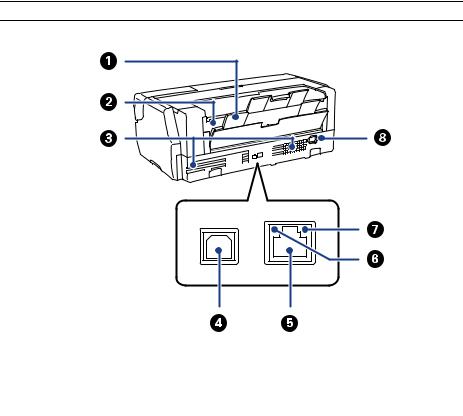
Figure 1-5. Back side |
|
Table 1-13. Back side |
|
|
No. |
Name |
|
|
1 |
Rear support |
|
|
2 |
Roll paper feeder |
|
|
3 |
Airflow vents |
|
|
4 |
USB port |
|
|
5 |
LAN port |
|
|
6 |
Status light |
|
|
7 |
Data light |
|
|
8 |
AC inlet |
|
|
PRODUCT DESCRIPTION |
Hardware Specifications |
24 |
|
|
|
SE Group Confidential (Related Staff Only)
SC-P800 series |
Revision B |
|
|
1.5 Control Panel Specifications
1.5.1 Control panel
OPERATION PANEL
|
|
Figure 1-6. Operation panel |
|
|
|
Table 1-14. Operation panel |
|
|
|
|
|
|
Name |
|
Function |
|
|
|
|
1 |
Power light |
|
On: The power is on. |
|
Off: The power is off. |
||
|
|
|
|
2 |
Power button |
|
Turns the power on and off. |
|
|
|
|
3 |
Back button |
|
Press to return to the previous screen while the Menu is |
|
displayed. |
||
|
|
|
|
|
|
|
|
4 |
Screen |
|
Displays the printer's status, menus, error messages, and so |
|
on. |
||
|
|
|
|
|
|
|
|
5 |
up and down buttons |
|
Press to select menu items and setting values when a menu |
|
is displayed. |
||
|
|
|
|
|
|
|
|
6 |
Home button |
|
Display the home screen. |
|
|
|
|
PRODUCT DESCRIPTION |
Control Panel Specifications |
25 |
|
|
|
SE Group Confidential (Related Staff Only)

SC-P800 series |
|
|
|
|
|
|
Revision B |
|
|
|
|
|
|
|
|
|
Table 1-15. LCD |
|
|
HOME SCREEN |
|
|
|
|
|
|
|
||
|
|
|
|
|
|
|
|
||
|
|
|
|
|
|
|
|
|
|
|
Home Screen View |
|
|
|
Name |
Function |
|
|
|
|
|
|
|
|
|
|
|
||
|
|
|
|
|
|
|
Indicates that the home screen is displayed. |
|
|
|
|
|
|
|
|
|
|
|
|
|
|
|
|
|
|
|
Indicates the selected Load Guide using the following |
|
|
|
|
|
|
|
|
|
icons. |
|
|
|
|
|
|
|
|
|
Auto sheet |
Fine art media |
|
|
|
|
|
|
|
|
feeder |
|
|
|
|
|
|
|
|
|
Poster board |
Roll paper |
|
|
|
|
|
1 |
Status icon |
|
|
|
|
|
|
|
|
|
|
|
|
|
|
|
|
|
|
|
|
|
Turns on when Thick Paper is set to On. |
|
|
|
|
Figure 1-7. Home screen |
|
|
|
|
|
|
|
|
|
|
|
|
|
|
|
|
|
|
|
|
|
|
|
|
Indicates that the ink is running low or the maintenance |
|
|
|
|
|
|
|
|
|
cartridge is running out of space. Prepare a new cartridge. |
|
|
|
|
|
|
|
|
|
|
|
|
|
|
|
|
|
|
|
Indicates the selected black ink using the following icons. |
|
|
|
|
|
|
|
|
|
Photo black |
Matte black |
|
|
|
|
|
|
|
|
ink |
ink |
|
|
|
|
|
|
|
|
|
|
|
PRODUCT DESCRIPTION |
Control Panel Specifications |
26 |
|
|
|
SE Group Confidential (Related Staff Only)

SC-P800 series |
Revision B |
|
|
Table 1-15. LCD
Name |
Function |
|
|
Displayed when connected to a wired LAN.
|
|
Displays the operation mode, radio wave status, and |
|
|
|
connection status for the wireless LAN. |
|
|
|
The icon is not displayed when the wireless LAN is |
|
|
|
disconnected. |
|
|
|
The number of lines indicates the radio wave strength. |
|
|
|
Strong |
Weak |
1 |
Status icon |
Searching or |
|
|
|
|
|
|
|
unavailable |
|
|
|
The icon changes as shown below depending on the |
|
|
|
operation mode. |
|
|
|
Infrastructure |
Ad hoc mode |
|
|
mode |
|
|
|
Wi-If Direct |
Simple AP mode |
|
|
|
|
|
|
mode |
|
|
|
|
|
|
|
Load Guide is displayed when paper is not loaded. You |
|
|
(Load Guide/ |
can continue by checking the selected Load Guide |
|
2 |
Media Setup) |
procedure on the screen. |
|
|
button |
Media Setup is displayed when paper is loaded. You can |
|
|
|
set the Media Size and Media Type. |
|
|
|
|
Table 1-15. LCD |
|
|
|
|
|
|
|
|
|
Name |
|
Function |
|
|
|
|
|
|
||
|
|
|
Displays the approximate amount of ink remaining and |
||
|
|
|
free space in the maintenance cartridge. |
|
|
|
|
|
Depending on the status of each cartridge, the icons |
||
|
|
|
change as shown below. |
|
|
|
|
|
|
Ink cartridge |
|
|
|
|
|
No error |
Ink low |
3 |
(Ink Remaining |
|
|
|
|
Display) button |
|
|
|
|
|
|
|
|
Maintenance cartridge |
|
|
|
|
|
|
No error |
The |
|
|
|
|
|
Maintenance |
|
|
|
|
|
Box is nearing |
|
|
|
|
|
the end of its |
|
|
|
|
|
service life. |
|
|
|
|
||
4 |
(BK Ink |
|
You can change from one type of black ink to another. |
||
|
Change) button |
|
|
|
|
|
|
|
|
||
|
(Network |
|
Displays the status of the printer's connection to the |
||
5 |
Summary |
|
computer. You can also display Wi-Fi/Network Settings |
||
|
Display) button |
|
and so on directly from the Menu. |
|
|
|
|
|
|
||
6 |
(Setup) button |
|
You can perform printer maintenance and adjust printer |
||
|
settings. |
|
|||
|
|
|
|
||
|
|
|
|
||
|
|
|
You can eject paper that has been loaded. |
||
|
|
|
The following can be performed when roll paper is |
||
|
|
|
loaded. |
|
|
7 |
(Cut/Eject) |
|
|
Move the end of the printed section to the cutting |
|
|
button |
|
|
position |
|
|
|
|
Eject roll paper after moving the end of the printed |
||
|
|
|
|
section to the cutting position |
|
|
|
|
Eject roll paper |
|
|
|
|
|
|
|
|
PRODUCT DESCRIPTION |
Control Panel Specifications |
27 |
|
|
|
SE Group Confidential (Related Staff Only)

SC-P800 series Revision B
1.5.2 Menu Descriptions |
|
|
|
|
|
||||
|
Set up menu |
|
|
|
|
|
|
|
|
|
|
|
|
|
|
Table 1-16. Set up menu |
|
||
|
|
|
|
|
|
|
|
|
|
|
Menu |
Menu Item / Setting Value (Shaded one is the default) |
|
Explanation |
|
||||
|
|
|
|
|
|
|
|
||
|
|
Print Head Nozzle Check |
Check whether the print head nozzles are clogged. Visually confirm the printed check pattern, and perform |
||||||
|
|
head cleaning if there are any blurred or missing sections. |
|
||||||
|
|
|
|
|
|
|
|
||
|
|
|
|
|
|
|
|
||
|
|
Print Head Cleaning |
|
|
Perform head cleaning if you notice banding or gaps in the print results. Cleans the print head to improve the |
||||
|
|
|
|
print quality. |
|
|
|||
|
|
|
|
|
|
|
|
|
|
|
|
|
|
|
|
|
|
|
|
|
|
Heavy Head Cleaning |
|
|
Use this if nozzles are clogged even after performing Print Head Cleaning several times. Note that this |
|
|||
|
|
|
|
consumes more ink than Print Head Cleaning. |
|
||||
|
|
|
|
|
|
|
|
||
Maintenance |
|
|
|
|
|
|
|
|
|
Paper Guide Cleaning |
|
|
Select this option to pass (feed and eject) plain paper through the printer and clean the rollers. |
|
|||||
|
|
|
|
|
|||||
|
|
|
|
|
|
|
|
|
|
|
|
|
|
|
|
On |
This option is only available when printing from a smart device. |
|
|
|
|
Thick Paper |
|
|
Set this if print results are scuffed or smeared. When this is set to On, print speed may slow down. Only use |
||||
|
|
|
Off |
||||||
|
|
|
|
|
|
this if scuffing occurs. When the printer is turned off, this setting returns to Off. |
|
||
|
|
|
|
|
|
|
|
||
|
|
|
|
|
|
|
|
|
|
|
|
Print Head Alignment |
|
|
If print results appear grainy or out of focus, perform Print Head Alignment to correct the print |
|
|||
|
|
|
|
misalignment. |
|
|
|||
|
|
|
|
|
|
|
|
|
|
|
|
|
|
|
|
|
|
|
|
|
|
|
|
|
|
|
|
|
|
|
|
|
|
|
Wi-Fi/Network Status |
Check network information. |
|
||
|
|
|
|
|
|
|
|
||
|
|
Network Status |
|
Wi-Fi Direct Status |
|
||||
|
|
|
|
|
|
||||
System |
|
|
|
|
|
|
|
|
|
|
|
|
Google Cloud Print Status |
|
|
|
|||
Administration |
|
|
|
|
|
|
|||
|
|
|
|
|
|
|
|
||
|
|
|
|
|
Configuration Status Sheet |
|
|
|
|
|
|
|
|
|
|
|
|
||
|
|
Print Status Sheet |
|
Supply Status Sheet |
Prints an information sheet for the current status and settings. |
|
|||
|
|
|
|
|
|
|
|
|
|
|
|
|
|
|
Usage History Sheet |
|
|
|
|
|
|
|
|
|
|
|
|
|
|
|
|
|
|
|
|
|
On |
Automatically displays the media setup screen when paper is loaded. |
|
|
|
|
|
|
|
Paper Setup Display |
|
When this is Off, AirPrint is unavailable. Also, Error Notice from Paper Source |
|
|
|
|
|
|
|
Off |
|
||
|
|
|
|
|
Paper Source |
|
Settings becomes Off. |
|
|
|
|
|
|
|
|
|
|
||
|
|
|
|
|
Settings |
|
|
|
|
|
|
|
|
|
Error Notice |
On |
Set whether or not to display an error if the paper size or type differ from the printer |
||
|
|
|
|
|
|
||||
|
|
|
|
|
|
|
|||
|
|
|
|
|
|
|
settings. |
|
|
System |
|
|
|
|
Off |
|
|||
|
|
|
|
|
|
||||
|
|
|
|
|
|
|
|||
Printer Settings |
|
|
|
|
|
|
|
||
Administration |
|
|
|
On |
This option only takes effect with fine art media and poster board. Select On to display an error in the control |
||||
|
|
|
|
||||||
|
|
|
|
|
Paper Skew Check |
|
panel’s screen when the paper is fed in at a slant. On is recommended, as feeding the paper at a slant can |
||
|
|
|
|
|
Off |
||||
|
|
|
|
|
|
cause the paper to jam. |
|
||
|
|
|
|
|
|
|
|
||
|
|
|
|
|
|
|
|
|
|
|
|
|
|
|
|
On |
When this is set to On, even if the print position moves on the loaded paper due to a cutting error or paper |
||
|
|
|
|
|
Horizontal Centered |
|
feed error, the printer detects the width of the paper and the image is adjusted and printed in the center. Even |
||
|
|
|
|
|
Off |
||||
|
|
|
|
|
|
if there is a paper cutting error or print position error, the margins are still set evenly on the left and right. |
|||
|
|
|
|
|
|
|
|||
|
|
|
|
|
|
|
|
|
|
|
|
|
|
|
|
|
|
|
|
PRODUCT DESCRIPTION |
|
Control Panel Specifications |
28 |
||||||
|
|
|
|
|
|
|
|
|
|
SE Group Confidential (Related Staff Only)

SC-P800 series |
|
|
Revision B |
|
|
|
Table 1-16. Set up menu |
|
|
|
|
|
|
|
Menu |
Menu Item / Setting Value (Shaded one is the default) |
|
Explanation |
|
|
|
|
|
|
System
Administration
|
Print Page Line |
On |
When this is set to On, a dotted line is printed on the roll paper. |
|||
|
|
|||||
|
Off |
|||||
|
|
|
|
|
||
|
|
|
|
|
|
|
|
|
On |
Select whether or not (On/Off) to detect the paper width. When this is set to Off, printing may be performed |
|||
|
|
|
beyond the edges of the paper. If printing is performed beyond the edges of the paper, the inside of the printer |
|||
Printer Settings |
Paper Size Check |
|
||||
Off |
will be soiled with ink. We recommend setting this to On. When selecting Off, borderless printing can not be |
|||||
|
|
|||||
|
|
|
|
|
||
|
|
|
performed. |
|
|
|
|
|
|
|
|
|
|
|
BK Ink Auto Change |
On |
When this is set to On, the black ink is changed automatically using the Media Type selected in the printer |
|||
|
|
|||||
|
Off |
driver. |
|
|
||
|
|
|
|
|||
|
|
|
|
|
||
|
|
|
|
|||
|
LCD Brightness |
1 to 9 |
You can adjust the brightness of the screen in nine stages. |
|||
|
|
|
|
|
|
|
|
|
|
High |
|
|
|
|
|
|
|
|
|
|
|
|
Button Press |
Medium |
|
|
|
|
|
|
|
|
||
|
|
Low |
|
|
||
|
|
|
|
|
||
|
|
|
|
|
|
|
|
|
|
Off |
|
|
|
|
|
|
|
|
|
|
|
|
|
High |
|
|
|
|
|
|
|
|
|
|
|
Sound |
Error Notice |
Medium |
|
Set whether or not to play a sound and the volume for operation sounds, error sounds, |
|
|
|
|
||||
|
|
|
and done sounds. |
|||
|
Low |
|
||||
|
|
|
|
|||
|
|
|
|
|
||
|
|
|
|
|
|
|
|
|
|
Off |
|
|
|
|
|
|
|
|
|
|
|
|
|
High |
|
|
|
|
|
|
|
|
|
|
Common Settings |
|
CompletionNotice |
Medium |
|
|
|
|
|
|
|
|||
|
|
Low |
|
|
||
|
|
|
|
|
||
|
|
|
|
|
|
|
|
|
|
Off |
|
|
|
|
|
|
|
|
||
|
Sleep Timer |
1 to 240 mins. |
Set the time to switch to sleep mode (energy saving mode) when the printer is not operated for a continuous |
|||
|
period. |
|
|
|||
|
|
|
|
|
||
|
|
|
|
|
|
|
|
|
Off |
|
|
|
|
|
|
|
|
|
|
|
|
|
30minutes |
|
|
|
|
|
|
|
|
|
|
|
|
|
1h |
Set whether or not to turn off the printer automatically, as well as setting the time until the printer |
|||
|
|
|
||||
|
Power Off Timer |
2 h |
automatically turns off when no printer operations are performed for a continuous period. The default setting |
|||
|
|
|
varies depending on the area of use. |
|||
|
|
4 h |
||||
|
|
|
|
|
||
|
|
|
|
|
|
|
|
|
8h |
|
|
|
|
|
|
|
|
|
|
|
|
|
12h |
|
|
|
|
PRODUCT DESCRIPTION |
Control Panel Specifications |
29 |
|
|
|
SE Group Confidential (Related Staff Only)

SC-P800 series |
|
|
|
|
Revision B |
|
|
|
|
|
Table 1-16. Set up menu |
||
|
|
|
|
|
|
|
Menu |
Menu Item / Setting Value (Shaded one is the default) |
Explanation |
||||
|
|
|
|
|
|
|
|
|
|
|
Date/Time |
Set the date and time. |
|
|
|
|
Date/Time Settings |
|
|
|
|
|
|
Time Difference |
Set the time difference from Coordinated Universal Time (UTC). Default: Since this is set to ±0:00, it does |
||
|
|
|
|
|||
|
|
|
|
not normally need to be changed. |
||
|
|
|
|
|
||
|
|
|
|
|
|
|
|
|
|
|
English |
|
|
|
|
|
|
|
|
|
|
|
|
|
French |
|
|
|
|
|
|
|
|
|
|
|
|
|
Italian |
|
|
|
|
|
|
|
|
|
|
|
|
|
German |
|
|
|
|
|
|
|
|
|
|
|
|
|
Spanish |
|
|
|
Common Settings |
|
|
|
||
System |
Language |
Portuguese |
Select the language for the screen display. The default setting varies depending on the area of use. |
|||
|
|
|||||
|
|
|
|
|
||
Administration |
|
|
|
|
|
|
|
|
|
Dutch |
|
||
|
|
|
|
|
||
|
|
|
|
|
|
|
|
|
|
|
Russian |
|
|
|
|
|
|
|
|
|
|
|
|
|
Simplified Chinese |
|
|
|
|
|
|
|
|
|
|
|
|
|
Traditional Chinese |
|
|
|
|
|
|
|
|
|
|
|
|
|
Korean |
|
|
|
|
|
|
|
|
|
|
|
|
Operation Timer Out |
On |
You are returned to the Home screen if no operations are performed for three minutes on each menu. |
|
|
|
|
|
|||
|
|
|
Off |
|||
|
|
|
|
|
||
|
|
|
|
|
|
|
|
Wi-Fi/Network |
Wi-Fi/Network Status |
|
Print a network status sheet. View network settings and connection status. |
||
|
Settings |
|
||||
|
|
|
|
|||
|
|
|
|
|
|
|
PRODUCT DESCRIPTION |
Control Panel Specifications |
30 |
|
|
|
SE Group Confidential (Related Staff Only)
 Loading...