


 Loading...
SERVICE MANUAL
9-pin Serial Impact Dot Matrix Printer
EPSON LX-300+
®
SEDM997003
Notice:
All rights reserved. No part of this manual may be reproduced, stored in a retrieval system, or transmitted in any form or by any means, electronic, mechanical, photocopying, recording, or otherwise, without the prior written permission of SEIKO EPSON CORPORATION.
The contents of this manual are subject to change without notice.
All effort have been made to ensure the accuracy of the contents of this manual. However, should any errors be detected, SEIKO EPSON would greatly appreciate being informed of them.
The above not withstanding SEIKO EPSON CORPORATION can assume no responsibility for any errors in this manual or the consequences thereof. EPSON is a registered trademark of SEIKO EPSON CORPORATION.
General Notice: |
Other product names used herein are for identification purpose only and may be trademarks or registered trademarks of their |
|
respective owners. EPSON disclaims any and all rights in those marks. |
Copyright © 2000 SEIKO EPSON CORPORATION. Printed in Japan.

PRECAUTIONS
Precautionary notations throughout the text are categorized relative to 1) Personal injury and 2) damage to equipment.
W A R Signals a precaution which, if ignored, could result in serious or fatal personal injury. Great caution should be exercised in performing procedures preceded by a WARNING heading.
Signals a precaution which, if ignored, could result in
C A U T IO N
damage to equipment.
The precautionary measures itemized below should always be observed when performing repair/maintenance procedures.
DANGER
1.ALWAYS DISCONNECT THE PRODUCT FROM THE POWER SOURCE AND PERIPHERAL DEVICES PERFORMING ANY MAINTENANCE OR REPAIR PROCEDURES.
2.NOWORK SHOULD BE PERFORMED ON THE UNIT BY PERSONS UNFAMILIAR WITH BASIC SAFETY MEASURES AS DICTATED FOR ALL ELECTRONICS TECHNICIANS IN THEIR LINE OF WORK.
3.WHEN PERFORMING TESTING AS DICTATED WITHIN THIS MANUAL, DO NOT CONNECT THE UNIT TO A POWER SOURCE UNTIL INSTRUCTED TO DO SO. WHEN THE POWER SUPPLY CABLE MUST BE CONNECTED, USE EXTREME CAUTION IN WORKING ON POWER SUPPLY AND OTHER ELECTRONIC COMPONENTS.
WARNING
1.REPAIRS ON EPSON PRODUCT SHOULD BE PERFORMED ONLY BY AN EPSON CERTIFIED REPAIR TECHNICIAN.
2.MAKE CERTAIN THAT THE SOURCE VOLTAGES IS THE SAME AS THE RATED VOLTAGE, LISTED ON THE SERIAL NUMBER/RATING PLATE. IF THE EPSON PRODUCT HAS A PRIMARY AC RATING DIFFERENT FROM AVAILABLE POWER SOURCE, DO NOT CONNECT IT TO THE POWER SOURCE.
3.ALWAYS VERIFY THAT THE EPSON PRODUCT HAS BEEN DISCONNECTED FROM THE POWER SOURCE BEFORE REMOVING OR REPLACING PRINTED CIRCUIT BOARDS AND/OR INDIVIDUAL CHIPS.
4.IN ORDER TO PROTECT SENSITIVE MICROPROCESSORS AND CIRCUITRY, USE STATIC DISCHARGE EQUIPMENT, SUCH AS ANTI-STATIC WRIST STRAPS, WHEN ACCESSING INTERNAL COMPONENTS.
5.REPLACE MALFUNCTIONING COMPONENTS ONLY WITH THOSE COMPONENTS BY THE MANUFACTURE; INTRODUCTION OF SECOND-SOURCE ICs OR OTHER NONAPPROVED COMPONENTS MAY DAMAGE THE PRODUCT AND VOID ANY APPLICABLE EPSON WARRANTY.
PREFACE
This manual describes basic functions, theory of electrical and mechanical operations, maintenance and repair procedures of LX-300+. The instructions and procedures included in here are intended for the experienced repair technicians, and close attention should be given to the precautions on the preceding page. Chapters are organized as follows:
CHAPTER 1. PRODUCT DESCRIPTIONS
Provides a general overview and specifications of the product.
CHAPTER 2. OPERATING PRINCIPLES
Describes the theory of electrical and mechanical operations of the product.
CHAPTER 3. TROUBLESHOOTING
Provides the step-by-step procedures for troubleshooting.
CHAPTER 4. DISASSEMBLY AND ASSEMBLY
Describes the step-by-step procedures for disassembling and assembling the product.
CHAPTER 5. ADJUSTMENT
Provides adjusting procedures.
CHAPTER 6. MAINTENANCE
Provides preventive maintenance procedures.
APPENDIX
Provides the following addition information for reference:
-Connector Summary
-Parts List
-Exploded Diagrams
-Component Layout
-Circuit Schematics

|
|
|
Revision Status |
||
|
|
|
|
|
|
Revision |
|
Date of Issue |
|
|
Description |
|
|
|
|
|
|
A |
|
May 11, 2000 |
|
|
First Release |
|
|
|
|
|
|
|
|
|
|
|
|
|
|
|
|
|
|
|
|
|
|
|
|
|
|
|
|
|
|

Contents
Chapter 1 Product Description |
|
1.1 Features .............................................................................................. |
9 |
1.2 Printing Specification ...................................................................... |
10 |
1.2.1 Printing Specification ................................................................. |
10 |
1.2.2 Paper Feeding ........................................................................... |
13 |
1.2.3 Electrical Specification .............................................................. |
14 |
1.2.4 Environmental Condition ........................................................... |
14 |
1.2.5 Reliability ................................................................................... |
14 |
1.2.6 Ribbon Cartridge ....................................................................... |
14 |
1.2.7 Safety Approvals ....................................................................... |
15 |
1.2.8 CE Marking ................................................................................ |
15 |
1.2.9 Acoustic noise: .......................................................................... |
15 |
1.2.10 Printable Area .......................................................................... |
16 |
1.3 Interface Specifications .................................................................. |
19 |
1.3.1 Parallel Interface (Forward Channel) ........................................ |
19 |
1.3.2 Parallel Interface (Reverse Channel) ........................................ |
21 |
1.3.3 Serial Interface .......................................................................... |
22 |
1.3.4 Interface Selection ..................................................................... |
23 |
1.3.5 Prevention Hosts from Data Transfer Time-out ......................... |
23 |
1.3.6 IEEE1284.4 protocol ................................................................. |
23 |
1.4 Operation .......................................................................................... |
24 |
1.4.1 Control Panel ............................................................................. |
24 |
1.4.1.1 Switches ............................................................................. |
24 |
1.4.1.2 LED .................................................................................... |
25 |
1.4.1.3 Buzzer ................................................................................ |
25 |
1.4.2 Functions ................................................................................... |
26 |
1.4.2.1 Usual Operation ................................................................. |
26 |
1.4.2.2 Operation at Power-on ....................................................... |
26 |
1.4.2.3 Default Setting .................................................................... |
26 |
1.4.2.4 Bi-d. Adjustment ................................................................. |
28 |
1.4.3 Errors ......................................................................................... |
28 |
1.5 Control codes .................................................................................. |
29 |
1.5.1 ESC/P2 ...................................................................................... |
29 |
|
1.5.2 IBM 2390 Plus Emulation .......................................................... |
30 |
|
1.5.3 Bi-Directional Commands ......................................................... |
31 |
|
1.5.3.1 Reply Printer Status ........................................................... |
33 |
|
1.5.3.2 Packet commands .............................................................. |
34 |
1.6 |
Initialization ...................................................................................... |
35 |
1.7 |
Paper Specifications ....................................................................... |
36 |
1.8 |
Physical Specifications .................................................................. |
39 |
1.9 |
Accessories ..................................................................................... |
40 |
Chapter 2 Operating Principles |
|
|
2.1 |
Overview .......................................................................................... |
42 |
2.2 |
Printer Mechanism (M-3M10) .......................................................... |
43 |
|
2.2.1 Printhead ................................................................................... |
44 |
|
2.2.1.1 Buzzer Function ................................................................. |
44 |
|
2.2.2 Carriage Mechanism ................................................................. |
45 |
|
2.2.2.1 High speed skip method ..................................................... |
47 |
|
2.2.3 Ribbon Mechanism ................................................................... |
47 |
|
2.2.3.1 Ink Ribbon Shifting Mechanism .......................................... |
47 |
|
2.2.3.2 Color Ribbon Driving Mechanism (Option) ......................... |
47 |
|
2.2.4 Platen Gap Adjustment Mechanism .......................................... |
49 |
|
2.2.5 Paper Feed Mechanism ............................................................ |
50 |
|
2.2.5.1 Page Length Measurement ................................................ |
51 |
|
2.2.6 Release Mechanism .................................................................. |
52 |
|
2.2.7 Other Special Functions ............................................................ |
52 |
|
2.2.7.1 Energy saving mode ........................................................... |
52 |
|
2.2.7.2 Quiet Mode ......................................................................... |
52 |
2.3 |
Electric Circuit Operating Principles ............................................. |
53 |
|
2.3.1 MAIN Board (Control Board) Electric Circuit ............................. |
53 |
|
2.3.2 C294PSB / C294PSE Board ..................................................... |
54 |
|
2.3.2.1 Electric Circuit .................................................................... |
54 |

Chapter 3 Troubleshooting |
|
3.1 Overview ........................................................................................... |
56 |
3.2 Troubleshooting .............................................................................. |
57 |
3.2.1 Initialization Check .................................................................... |
57 |
3.2.2 Check Performance By Self-Check Function ............................ |
57 |
3.2.2.1 Indicator LED ...................................................................... |
57 |
3.2.3 Identify Problems From Symptoms ........................................... |
58 |
3.2.4 Unit and Parts Check ................................................................ |
61 |
3.2.4.1 Printhead Check ................................................................. |
61 |
3.2.4.2 Motor Check ....................................................................... |
62 |
3.2.4.3 Sensor Check ..................................................................... |
62 |
3.2.4.4 Printhead Driver Check ...................................................... |
63 |
Chapter 4 Disassembly and Assembly |
|
4.1 Overview ........................................................................................... |
65 |
4.1.1 Precautions ............................................................................... |
65 |
4.1.2 Tools .......................................................................................... |
65 |
4.1.3 Service Checks After Repair ..................................................... |
66 |
4.2 Disassembly and Assembly ........................................................... |
67 |
4.2.1 Printhead Removal .................................................................... |
68 |
4.2.2 Upper Housing Removal ........................................................... |
69 |
4.2.3 Printer Mechanism Removal ..................................................... |
70 |
4.2.4 Board Assembly and Panel Removal ........................................ |
71 |
4.2.5 C294MAIN Board Assembly Removal ...................................... |
71 |
4.2.6 P/S Board Assembly Removal .................................................. |
72 |
4.2.7 Printer Mechanism Disassembly ............................................... |
73 |
4.2.7.1 CR Motor Assembly Removal ............................................ |
73 |
4.2.7.2 Platen Removal .................................................................. |
74 |
4.2.7.3 Carriage Unit Removal ....................................................... |
75 |
4.2.7.4 Ribbon Feed Mechanism Removal .................................... |
76 |
4.2.7.5 RPE Sensor Removal ........................................................ |
77 |
4.2.7.6 BPE Sensor Removal ......................................................... |
77 |
4.2.7.7 HP Sensor Removal ........................................................... |
77 |
4.2.7.8 PG Sensor Removal ........................................................... |
78 |
4.2.7.9 Release Lever Position Sensor Removal ........................... |
78 |
4.2.7.10 PF Motor Assembly Removal ........................................... |
79 |
4.2.7.11 Paper Feed Mechanism Disassembly .............................. |
79 |
|
4.2.7.12 Paper Guide Removal |
...................................................... 81 |
Chapter 5 Adjustment |
|
|
5.1 |
Overview .......................................................................................... |
83 |
|
5.1.1 Platen Gap Adjustment ............................................................. |
83 |
|
5.1.2 Bi-D Adjustment ........................................................................ |
84 |
Chapter 6 Maintenance |
|
|
6.1 |
Maintenance ..................................................................................... |
89 |
|
6.1.1 Cleaning .................................................................................... |
89 |
|
6.1.2 Lubrication ................................................................................. |
89 |
Chapter 7 Appendix |
|
|
7.1 |
Connector Summary ....................................................................... |
94 |
7.2 |
Parts List .......................................................................................... |
97 |
7.3 |
Exploded Diagrams ....................................................................... |
100 |
7.4 |
Component Layout ....................................................................... |
102 |
7.5 |
Circuit Schematics ........................................................................ |
103 |

C H A P T E R
1
PRODUCT DESCRIPTION

LX-300+ |
Revision A |
1.1 Features
EPSON LX-300+ is a 9-pin serial impact dot matrix printer. The major features of this printer are as follows:
Printing speed: |
High speed draft |
300 cps at 10 cpi |
|
Draft |
225 cps at 10 cpi |
|
NLQ |
56 cps at 10 cpi |
Feeding method: |
Friction feed (rear) |
|
|
Push tractor feed (rear) |
|
|
Push and Pull tractor feed (rear) |
|
|
Pull tractor feed (rear, bottom) |
|
Feeder: |
Rear push tractor, CSF single-bin (Option), |
|
|
Pull tractor (Option) and Roll paper holder (Option) |
|
Paper/ Media: |
Single sheet, Continuous paper, Multi part paper, |
|
|
Envelope, Label and Roll paper |
|
Fonts: |
2NLQ and 1 Draft Bitmap typefaces |
|
|
8 Barcode fonts |
|
Character tables: |
Standard version |
13 tables |
|
NLSP version |
38 tables |
Input buffer: |
8 Kbytes |
|
Acoustic noise: |
49 dB(A) (ISO 7779 pattern) |
|
Reliability: |
Total print volume |
12 million lines |
|
|
(except printhead) |
|
MTBF |
6000 POH (25% Duty) |
|
Printhead life |
200 million strokes/ wire |
|
Ribbon life |
3 million characters |
Interface: |
Bi-directional parallel interface |
|
|
(IEEE-1284 nibble mode supported) |
|
|
Serial I/F |
|
Control code: |
ESC/P and IBM 2380 Plus emulation |
|
Copy capability: 1 original + 4 copies
Control panel functions:Font, Pause, Tear off, LF/FF, Load/ Eject, Micro Adjust, Self test, Data dump and the default settings
Paper guide cover
Printer cover
Control panel
Parallel interface
Tractor
Paper cord
Paper supports
Paper guide
Paper release lever
Knob
Ribbon cartridge
Paper thickness
lever
Paper tension unit
Power switch
Figure 1-1. EPSON LX-300+ Printer Parts
Product Description |
Features |
9 |

LX-300+ |
Revision A |
1.2 |
Printing Specification |
|
|
|
|
||||||
1.2.1 |
Printing Specification |
|
|
|
|
||||||
Print method: |
|
Impact dot matrix |
|
|
|
||||||
Number of pins: |
|
9 pins |
|
|
|
|
|||||
Print pin arrangement: |
9x1 |
|
|
|
|
||||||
Print pin diameter: |
0.29 mm (0.0114 inch) |
|
|
|
|||||||
Color (Option): |
|
Black, Magenta, Cyan, Yellow |
|||||||||
Print direction: |
|
Bi-direction with logic seeking |
|||||||||
Print speed and printable columns: |
|
|
|
|
|||||||
|
Table 1-1. Print Speed and Printable Columns |
||||||||||
|
|
|
|
|
|
|
|
|
|
|
|
Printing mode |
|
|
Character pitch |
|
|
Printable |
|
Printing speed |
|
||
|
|
(cpi) |
|
|
|
columns |
|
(cps) |
|
||
|
|
|
|
|
|
|
|
|
|||
|
|
|
|
|
|
|
|
|
|
|
|
High speed draft |
|
|
10 |
|
|
|
80 |
|
300 |
|
|
|
|
|
|
|
|
|
|
|
|
|
|
|
|
|
|
12 |
|
|
|
96 |
|
337 |
|
|
|
|
|
|
|
|
|
|
|
|
|
|
|
|
|
15 |
|
|
|
120 |
|
337 |
|
|
|
|
|
|
|
|
|
|
|
|
|
High speed draft |
|
|
17 |
|
|
|
137 |
|
321 |
|
|
condensed |
|
|
|
|
|
|
|
|
|
|
|
|
|
20 |
|
|
|
160 |
|
300 |
|
||
|
|
|
|
|
|
|
|
|
|||
|
|
|
|
|
|
|
|
|
|
|
|
Draft |
|
|
|
10 |
|
|
|
8- |
|
225 |
|
|
|
|
|
|
|
|
|
|
|
|
|
|
|
|
|
12 |
|
|
|
96 |
|
270 |
|
|
|
|
|
|
|
|
|
|
|
|
|
|
|
|
|
15 |
|
|
|
120 |
|
225 |
|
|
|
|
|
|
|
|
|
|
|
|
|
Draft condensed |
|
|
17 |
|
|
|
137 |
|
191 |
|
|
|
|
|
|
|
|
|
|
|
|
|
|
|
|
|
|
20 |
|
|
|
160 |
|
225 |
|
|
|
|
|
|
|
|
|
|
|
|
|
Draft emphasized |
|
|
10 |
|
|
|
80 |
|
112 |
|
|
|
|
|
|
|
|
|
|
|
|
|
|
Table 1-1. Print Speed and Printable Columns
Printing mode |
|
Character pitch |
|
Printable |
|
Printing speed |
|
(cpi) |
|
columns |
|
(cps) |
|
|
|
|
|
|||
|
|
|
|
|
|
|
NLQ |
|
10 |
|
80 |
|
56 |
|
|
|
|
|
|
|
|
|
12 |
|
96 |
|
67 |
|
|
|
|
|
|
|
|
|
15 |
|
120 |
|
56 |
|
|
|
|
|
|
|
|
|
17 |
|
137 |
|
47 |
|
|
|
|
|
|
|
|
|
20 |
|
160 |
|
56 |
|
|
|
|
|
|
|
NOTE: When the power supply voltage drops to the lower limit, the printer stops printing and then starts printing the rest on the line more slowly than before.
Resolution:
Table 1-2. Resolution
Printing mode |
|
Horizontal density |
|
Vertical density |
|
|
Adjacent dot print |
|
(dpi) |
|
(dpi) |
|
|
||
|
|
|
|
|
|
||
|
|
|
|
|
|
|
|
High speed draft |
|
90 |
|
72 |
|
|
No |
|
|
|
|
|
|
|
|
Draft |
|
120 |
|
72 |
|
|
No |
|
|
|
|
|
|
|
|
Draft condensed |
|
240 |
|
72 |
|
|
No |
|
|
|
|
|
|
|
|
Draft emphasized |
|
120 |
|
72 |
|
|
Yes |
|
|
|
|
|
|
|
|
NLQ |
|
240 |
|
144 |
|
|
No |
|
|
|
|
|
|
|
|
Bit image |
|
60, 72, 80, 90 or 120 |
|
72 |
|
|
Yes |
|
|
|
|
|
|
|
|
|
|
120 or 240 |
|
72 |
|
|
No |
|
|
|
|
|
|
|
|
Control code: |
|
ESC/P and IBM 2380 Plus emulation |
|||||
|
|
(Refer to 1.5 "Control codes") |
|
||||
Product Description |
Printing Specification |
10 |
LX-300+ |
Revision A |
Character tables:
Standard version (13 character table)
Italic table |
PC437 (US, Standard Europe) |
PC850 (Multilingual) |
PC860 (Portuguese) |
PC863 (Canadian-French) |
PC865 (Nordic) |
PC861 (Icelandic) |
BRASCII |
Abicomp |
Roman 8 |
ISO Latin 1 |
PC858 |
ISO 8859-15 |
|
NLSP version (38 character tables)
Italic table |
PC437 (US, Standard Europe) |
PC850 (Multilingual) |
PC437 Greek |
PC853 (Turkish) |
PC855 (Cyrillic) |
PC852 (East Europe) |
PC857 (Turkish) |
PC866 (Russian) |
|
PC869 (Greek) |
MAZOWIA (Poland) |
Code MJK (CSFR) |
ISO 8859-7 (Latin / Greek) |
ISO Latin 1T (Turkish) |
Bulgaria (Bulgarian) |
PC 774 (LST 1283:1993) |
Estonia (Estonia) |
ISO 8859-2 |
PC 866 LAT. (Latvian) |
PC 866 UKR (Ukrania) |
PC860 (Portuguese) |
PC 861 (Icelandic) |
PC865 (Nordic) |
PC APTEC (Arabic) |
PC708 (Arabic) |
PC 720 (Arabic) |
PCAR864 (Arabic) |
PC863 (Canadian-French) |
Abicomp |
BRASCII |
Roman 8 |
ISO Latin 1 |
Hebrew 7*1 |
Hebrew 8*1 |
PC862 (Hebrew)*1 |
PC858 |
IAO8859-15 |
PC771 (Lithuania) |
|
NOTE: *1: This item is not displayed on a default setting mode. Do not describe this in the manual.
International character sets: 13 countries
U.S.A |
France |
Germany |
U.K. |
Denmark 1 |
Sweden |
Italy |
Spain 1 |
Japan |
Norway |
Denmark 2 |
Spain 2 |
Latin America |
|
|
NOTE: The international and legal characters are the following 12 codes;
23H, 24H, 40H, 5BH, 5CH, 5DH, 5EH, 60H, 7BH, 7CH, 7DH, 7EH.
Typeface
Bit map fonts: |
|
EPSON Draft |
10cpi, 12cpi, 15cpi |
EPSON Roman |
10cpi, 12cpi, 15cpi, Proportional |
EPSON Sans serif |
10cpi, 12cpi, 15cpi, Proportional |
EPSON OCR-B |
10cpi*1 |
NOTE: *1: Do not describe in manual.
Bar codes |
|
|
EAN-13 |
EAN-8 |
Interleaved 2 of 5 |
UPC-A |
UPC-E |
Code 39 |
Code 128 |
POSTNET |
Coda bar (NW-7)*1 |
Industrial 2 of 5 *1 |
Matrix 2 of 5 *1 |
|
NOTE: *1: Do not describe in manual.
Product Description |
Printing Specification |
11 |

LX-300+ |
Revision A |
Character tables and typefaces:
Table 1-3. Character Tables and Typefaces
|
|
|
Character table |
|
Bitmap font |
|
|
|
|
|
|
|
|
Standard |
|
Italic table |
|
|
EPSON Draft |
|
version |
|
PC 437 (US, Standard Europe) |
|
EPSON Roman |
||
|
|
|
|
|
|
EPSON Sans serif |
|
|
|
|
|
|
EPSON OCR-B |
|
|
|
|
|
|
|
|
|
PC 850 |
(Multilingual) |
BRASCII |
|
EPSON Draft |
|
|
PC 860 |
(Portuguese) |
Abicomp |
|
EPSON Roman |
|
|
PC 863(Canadian- |
Roman 8 |
|
EPSON Sans serif |
|
|
|
French) |
ISO Latin 1 |
|
|
|
|
|
PC 865 |
(Nordic) |
PC 858 |
|
|
|
|
PC 861 |
(Icelandic) |
ISO 8859-15 |
|
|
|
|
|
|
|
|
|
Table 1-3. Character Tables and Typefaces
|
|
Character table |
|
|
Bitmap font |
|
|
|
|
|
|
|
|
NLSP |
|
Italic table |
|
|
|
EPSON Draft |
version |
|
PC 437(US, Standard Europe) |
|
|
EPSON Roman |
|
|
|
|
|
|
|
EPSON Sans serif |
|
|
|
|
|
|
EPSON OCR-B |
|
|
|
|
|
|
|
|
|
PC 860(Portuguese) |
PC 850 |
(Multilingual) |
|
EPSON Draft |
|
|
PC 865(Nordic) |
PC 861 (Icelandic) |
|
EPSON Roman |
|
|
|
BRASCIl |
PC863 (Canadian- |
|
EPSON Sans serif |
|
|
|
Roman 8 |
French) |
|
|
|
|
|
PC437 (Greek) |
Abicomp |
|
|
|
|
|
PC 855 (Cyrillic) |
lSOLatin1 |
|
|
|
|
|
PC 857 (Turkish) |
PC 853 (Turkish) |
|
|
|
|
|
PC 869 (Greek) |
PC 852 |
(East Europe) |
|
|
|
|
Code MJK (CSFR) |
PC 866 |
(Russian) |
|
|
|
|
lSO Latin 1T (Turkish) |
MAZOWIA (Poland) |
|
|
|
|
|
PC774 (LST 1283: 1993) |
lSO 8859-7 (Latin/ |
|
|
|
|
|
1SO 8859-2 |
Greek) |
|
|
|
|
|
PC 866 UKR (Ukrania) |
Bulgaria (Bulgarian) |
|
|
|
|
|
PC 708 (Arabic) |
Estonia (Estonia) |
|
|
|
|
|
PCAR864 (Arabic) |
PC 866 |
LAT. (Latvian) |
|
|
|
|
Hebrew 8*1 |
PC APTEC (Arabic) |
|
|
|
|
|
PC 858 |
PC 720 |
(Arabic) |
|
|
|
|
Hebrew7*1 |
|
|
||
|
|
PC771 (Lithuania) |
|
|
||
|
|
PC862 (Hebrew)*1 |
|
|
||
|
|
|
|
|
||
|
|
|
ISO 8859-15 |
|
|
|
|
|
|
|
|
|
|
NOTE: ESC R command is effective on all the character tables.
NOTE: *1: These items are not displayed in the default setting mode. Do not describe in the manual.
Product Description |
Printing Specification |
12 |

LX-300+ |
Revision A |
1.2.2 Paper Feeding
Feeding method: |
Friction feed (rear) |
|
|
Push tractor feed (rear) |
|
|
Push and Pull tractor feed (rear) |
|
|
Pull tractor feed (rear, bottom) |
|
Feeder: |
Rear push tractor, CSF single-bin (Option), |
|
|
Pull tractor (Option) and Roll paper holder (Option) |
|
Paper path: |
Manual insertion |
Rear in, top out |
|
CSF |
Rear in, top out |
|
Push Tractor |
Rear in, top out |
|
Pull Tractor |
Rear or bottom in, top out |
Line spacing: |
4.23mm (1/6 inch) or programmable |
|
|
in increments of 0.118mm (1/216 inch) |
|
Feed speed: |
4.23mm (1/6 inch feed) |
88msec |
|
Continuous feed |
0.76MPS (m/sec) |
|
|
[3.0 IPS (inches/sec)] |
Input Data Buffer: 8 Kbyte
Release lever:
The release lever must be set according to the following table;
Table 1-4. Release Lever
Lever position |
|
Paper path/ Feeder |
|
Paper/ Media |
|
|
|
|
|
Friction |
|
Manual insertion (rear) |
|
Cut sheet (Single sheet and |
|
|
|
|
Multi part) |
|
|
|
|
Envelop |
|
|
|
|
|
|
|
CSF single-bin |
|
Cut sheet (Single sheet) |
|
|
|
|
|
|
|
Roll paper holder feed (rear) |
|
Roll paper |
|
|
|
|
|
Table 1-4. Release Lever
Lever position |
|
Paper path/ Feeder |
|
Paper/ Media |
|
|
|
|
|
Tractor |
|
Push tractor feed (rear) |
|
Continuous paper (Single |
|
|
|
|
sheet and Multi part) |
|
|
|
|
|
|
|
Push and Pull tractor feed |
|
Continuous paper (Single |
|
|
(rear) |
|
sheet and Multi part) |
|
|
|
|
|
|
|
Pull tractor feed (rear) |
|
Continuous paper (Single |
|
|
|
|
sheet and Multi part) |
|
|
|
|
|
|
|
Pull tractor feed (bottom) |
|
Continuous paper (Single |
|
|
|
|
sheet and Multi part) |
|
|
|
|
Labels |
|
|
|
|
|
Paper thickness lever:
The paper thickness lever must be set at the proper position as shown below.
Table 1-5. Paper Thickness Lever
Lever |
|
Paper thickness (inch) |
|
Paper thickness (mm) |
||
|
|
|
|
|
||
position |
|
|
|
|
|
|
|
Minimum |
|
Maximum |
|
||
|
|
|
|
|||
|
|
|
|
|
||
|
|
|
|
|
|
|
0 |
|
(0.0024) |
|
(0.0071) |
|
over 0.06 up to 0.18 |
|
|
|
|
|
|
|
1 |
|
(0.0071) |
|
(0.0102) |
|
over 0.18 up to 0.26 |
|
|
|
|
|
|
|
2 |
|
(0.0102) |
|
(0.0130) |
|
over 0.26 up to 0.33 |
|
|
|
|
|
|
|
3 |
|
(0.0130) |
|
(0.0154) |
|
over 0.33 up to 0.39 |
|
|
|
|
|
|
|
4 |
|
(0.0154) |
|
(0.0205) |
|
over 0.39 up to 0.52 |
|
|
|
|
|
|
|
Product Description |
Printing Specification |
13 |
LX-300+ |
Revision A |
1.2.3 Electrical Specification
120 V version
|
Rated voltage: |
AC 120V |
|
Input voltage range: |
AC 99 to 132 V |
Rated frequency range: 50 to 60 Hz
Input frequency range: 49.5 to 60.5 Hz
|
Rated current: |
0.6A (max. 1.4A) |
|
Power consumption: |
approx. 23W (ISO/IEC 10561 Letter pattern) |
|
Insulation resistance: |
10MΩ min. |
|
|
(between AC line and chassis, DC 500V) |
|
Dielectric strength: |
AC 1000 Vrms. 1 min. or |
|
|
AC 1200 Vrms. 1 sec. |
|
|
(between AC line and chassis) |
230 V version
Rated voltage range: AC 220 to 240 V
Input voltage range: AC 198 to 264 V
Rated frequency range: 50 to 60 Hz
Input frequency range: 49.5 to 60.5 Hz
Rated current: |
0.3 A (max. 0.7A) |
Power consumption: approx. 23W (ISO/IEC10561 Letter pattern)
Insulation resistance: 10MΩ min.
(between AC line and chassis, DC 500V)
Dielectric strength: AC 1500 Vrms. 1 min. (between AC line and chassis)
1.2.4 Environmental Condition
Temperature: |
5 to 35 °C (operating*1) |
|
|
15 to 25 °C (operating*1,*2) |
|
|
-30 to 60 °C (non-operating) |
|
Humidity: |
10 to 80% |
RH (operating*1) |
|
30 to 60% |
RH (operating*1,*2) |
|
0 to 85% RH (non-operating) |
|
Resistance to shock: |
1 G, within 1ms (operating) |
|
2G, within 2ms (non-operating*3)
Resistance to vibration: 0.25 G, 10 to 55 Hz (operating)
0.50 G, 10 to 55 Hz (non-operating*3)
*1: without condensation
*2: during printing on multi part paper, envelop, card, or label *3: without shipment container
1.2.5 Reliability
Total print volume:12 million lines (except printhead)
MTBF: |
6000 POH |
Printhead life: |
400 million strokes / wire (Black) |
|
100 million strokes / wire (Color) |
1.2.6 Ribbon Cartridge |
|
Type: |
Fabric |
Color: |
Black |
Ribbon life: |
3 million characters |
|
(Draft 10 cpi, 14 dots/character) |
Type: |
Fabric |
Color: |
Black, Magenta, Cyan and Yellow |
Ribbon life:
|
Black |
1 million characters (Draft 10 cpi, 14 dots/character) |
|
Magenta |
0.7 million characters (Draft 10 cpi, 14 dots/character) |
|
Cyan |
0.7 million characters (Draft 10 cpi, 14 dots/character) |
Product Description |
Printing Specification |
14 |
LX-300+ |
|
Revision A |
|
|
Yellow |
0.5 million characters (Draft 10 cpi, 14 dots/character) |
|
1.2.7 |
Safety Approvals |
||
120 V version |
|
|
|
|
Safety standards: |
UL1950 |
|
|
|
|
CSA C22.2 No. 950 |
|
EMI: |
|
FCC part15 subpart B class B |
|
|
|
CSA C108.8 class B |
230 V version |
|
|
|
|
Safety standards: |
EN60950 (VDE) |
|
|
EMI: |
|
EN55022 (CISPR pub.22) class B |
|
|
|
AS/NZS 3548 class B |
1.2.8 CE Marking
230 V version and UPS version
Low voltage directive 73/23/EEC: EN60950
EMC Directive 89/336/EEC: |
EN55022 class B |
|
EN61000-3-2 |
|
EN61000-3-3 |
|
EN50082-1 |
|
IEC801-2 |
|
IEC801-3 |
|
IEC801-4 |
1.2.9 |
Acoustic noise: |
Level: |
49 dB(A) (ISO 7779 pattern) |
Product Description |
Printing Specification |
15 |
LX-300+ |
Revision A |
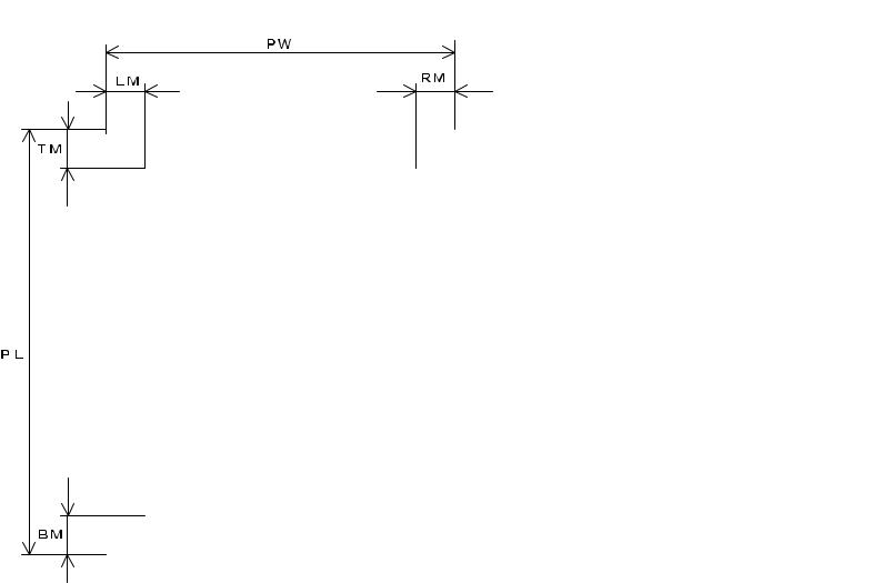
1.2.10 Printable Area |
|
Table 1-6. Printable Area for Cut Sheet |
|||||||
Cut sheets |
|
|
|
|
|
|
|||
|
|
|
Single Sheet |
|
Multi Part |
||||
|
|
|
|
|
|
|
|
|
|
|
|
|
|
|
PW (Width) |
|
Refer to 1.7 "Paper |
|
Refer to 1.7 "Paper |
|
|
|
|
|
|
|
Specifications" |
|
Specifications" |
|
|
|
|
|
|
|
|
|
|
|
|
|
|
|
PL (Length) |
|
Refer to 1.7 "Paper |
|
Refer to 1.7 "Paper |
|
|
|
|
|
|
|
Specifications" |
|
Specifications" |
|
|
|
|
|
|
|
|
|
|
|
|
|
|
|
LM (Left Margin) |
|
When PW<=229 mm: |
|
When PW<=229 mm: |
|
|
|
|
|
|
|
3 mm or more |
|
3 mm or more |
|
|
|
|
|
|
|
When PW=257 mm: |
|
When PW=257 mm: |
|
|
|
|
|
|
|
24mm or more |
|
24mm or more |
|
|
|
|
|
|
||||
|
|
|
|
|
|
|
|
|
|
|
|
|
|
|
RM (Right Margin) |
|
When PW<=229 mm: |
|
When PW<=229 mm: |
|
|
|
|
|
|
|
3 mm or more |
|
3 mm or more |
|
|
|
|
|
|
|
When PW=257 mm: |
|
When PW=257 mm: |
|
|
|
|
|
|
|
24mm or more |
|
24mm or more |
|
|
|
|
|
|
|
|
|
|
|
|
|
|
|
TM (Top Margin) |
|
4.2 mm or more |
|
4.2 mm or more |
|
|
|
|
|
|
|
|
|
|
|
|
|
|
|
BM (Bottom Margin) |
|
4.2 mm or more |
|
4.2 mm or more |
|
|
|
|
A r e |
|
|
|
|
|
|
|
P r i n t a b l |
e |
aNOTE: The maximum horizontal printable area is 203.2mm. |
|||||
|
|
|
|
|
|
|
|
|
|
|
|
|
|
|
|
|
|
|
|
Figure 1-2. Printable Area for Cut Sheet
Product Description |
Printing Specification |
16 |
LX-300+ |
Revision A |
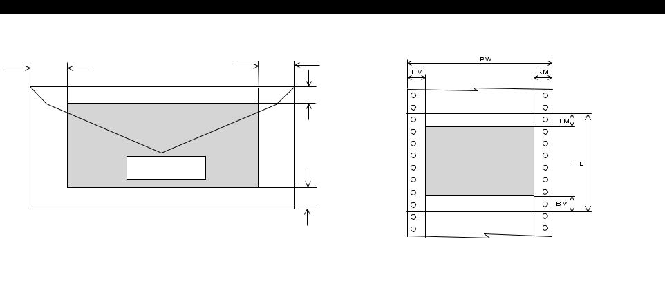
Envelop |
Continuous paper |
L M |
R M |
|
|
|
T M |
|
P e r f o r a t i o n |
|
P r i n t a b l e A r e |
|
P r in t a b le A r e a |
|
B M |
|
P e r f o r a t i o n |
Figure 1-3. Printable Area for Envelop
Figure 1-4. Printable Area for Continuous Paper
Table 1-7. Printable Area for Envelop
|
|
Envelope Printable Area |
|
|
|
PW (Width) |
|
Refer to 1.7 "Paper Specifications" |
|
|
|
PL (Length) |
|
Refer to 1.7 "Paper Specifications" |
|
|
|
LM (Left Margin) |
|
3 mm or more |
|
|
|
RM (Right Margin) |
|
3 mm or more |
|
|
|
TM (Top Margin) |
|
4.2 mm or more |
|
|
|
BM (Bottom Margin) |
|
4.2 mm or more |
|
|
|
NOTE: The maximum horizontal printable area is 203.2mm.
Table 1-8. Printable Area for Continuous Paper
|
|
Continuous Paper |
|
|
|
PW (Width) |
|
Refer to 1.7 "Paper Specifications" |
|
|
|
PL (Length) |
|
Refer to 1.7 "Paper Specifications" |
|
|
|
LM (Left Margin) |
|
When PW<=254mm: |
|
|
13 mm or more |
|
|
When PW=254 mm: |
|
|
24mm or more |
|
|
|
RM (Right Margin) |
|
When PW<=254mm: |
|
|
13 mm or more |
|
|
When PW=254 mm: |
|
|
24mm or more |
|
|
|
TM (Top Margin) |
|
4.2 mm or more |
|
|
|
BM (Bottom Margin) |
|
4.2 mm or more |
|
|
|
NOTE: The maximum horizontal printable area is 203.2mm.
Product Description |
Printing Specification |
17 |
LX-300+ |
Revision A |
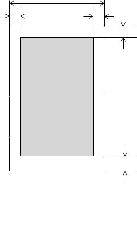
Roll paper
P W
L M B M
T M
P r in t a b le A r e a
B M
Figure 1-5. Printable Area for Roll Paper
Table 1-9. Printable Area for Roll Paper
|
|
Continuous Paper |
|
|
|
PW (Width) |
|
Refer to 1.7 "Paper Specifications" |
|
|
|
PL (Length) |
|
Refer to 1.7 "Paper Specifications" |
|
|
|
LM (Left Margin) |
|
3 mm or more |
|
|
|
RM (Right Margin) |
|
3 mm or more |
|
|
|
TM (Top Margin) |
|
4.2 mm or more |
|
|
|
BM (Bottom Margin) |
|
4.2 mm or more |
|
|
|
Product Description |
Printing Specification |
18 |
LX-300+ |
Revision A |
1.3 Interface Specifications
LX-300+ provides bi-directional 8 bit parallel interface and serial interface. Optional interface board is not supported on this model.
1.3.1 Parallel Interface (Forward Channel)
Transmission mode: |
8 bit parallel |
|
IEEE-1284 compatibility mode |
Adaptable connector: |
57-30360 (Amphenol) or equivalent |
Synchronization: |
-STROBE pulse |
Handshaking: |
BUSY and -ACKLG signals |
Signal level: |
TTL compatible |
|
(IEEE-1284 level 1 device) |
Table 1-10. Parameter
Parameter |
|
Minimum |
|
Maximum |
|
Condition |
|
|
|
|
|
|
|
VOH* |
|
-- |
|
5.5V |
|
|
VOL* |
|
-0.5V |
|
-- |
|
|
IOH* |
|
-- |
|
0.32mA |
|
VOH=2.4V |
IOL* |
|
-- |
|
12mA |
|
VOL=2.4V |
CO |
|
-- |
|
50pF |
|
|
VIH |
|
-- |
|
2.0V |
|
|
VIL |
|
0.8V |
|
-- |
|
|
IIH |
|
-- |
|
0.32mA |
|
VIH=2.0V |
IIL |
|
-- |
|
12mA |
|
VIL=0.8V |
CI |
|
-- |
|
50pF |
|
|
* Logic-H signal is 2.0V or lower when the printer is off and the signal is 3.0V or higher when the printer is on. The receiver has impedance which is equivalent to 7.5 kΩ.
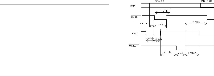
Figure 1-6. Data Transmitting Timing
Table 1-11. Maximum & Minimum Timings for Data Transmission
Parameter |
|
Minimum |
|
Maximum |
|
|
|
|
|
tsetup |
|
500 nsec |
|
-- |
thold |
|
500 nsec |
|
-- |
tstb |
|
500 nsec |
|
-- |
tready |
|
0 |
|
-- |
tbusy |
|
-- |
|
500 nsec |
treply |
|
-- |
|
-- |
tack |
|
500 nsec |
|
10 us |
tnbusy |
|
0 |
|
-- |
tnext |
|
0 |
|
-- |
ttout* |
|
-- |
|
120 nsec |
ttin** |
|
-- |
|
200 nsec |
*Rise and fall time of output signals
**Rise and fall time of input signals.
Product Description |
Interface Specifications |
19 |

LX-300+ |
Revision A |
BUSY signal is active (HIGH level) under the conditions below:
In the process of receiving data
In the condition of being input buffer full
In the condition of being -INT signal active (low level)
During hardware initialization
In the condition of being -ERROR or PE signal is active (low level, high level, respectively)
In the self test mode
In the adjustment mode
In the default-setting mode
-ERROR signal is active (low level) under the conditions below:
In the condition of a paper-out error
In the condition of a release lever error
PE signal is active (high level) under the condition below:
In the condition of a paper-out error
Table 1-12. Connector Pin Assignment and Signals
Pin |
|
Signal |
|
Return |
|
|
|
|
|
|
GND |
|
In/Out |
|
Functional Description |
||
No. |
|
Name |
|
|
|
|||
|
|
Pin |
|
|
|
|
||
|
|
|
|
|
|
|
|
|
|
|
|
|
|
|
|
|
|
1 |
|
-STROBE |
|
19 |
|
In |
|
Strobe pulse. Input data is latched at |
|
|
|
|
falling edge of the signal. |
||||
|
|
|
|
|
|
|
|
|
|
|
|
|
|
|
|
|
|
2 |
|
DATA1 |
|
20 |
|
In |
|
Parallel input data to the printer. |
|
|
|
|
bit0:LSB |
||||
|
|
|
|
|
|
|
|
|
|
|
|
|
|
|
|
|
|
3 |
|
DATA2 |
|
21 |
|
In |
|
bit1 |
|
|
|
|
|
|
|
|
|
4 |
|
DATA3 |
|
22 |
|
In |
|
bit2 |
|
|
|
|
|
|
|
|
|
5 |
|
DATA4 |
|
23 |
|
In |
|
bit3 |
|
|
|
|
|
|
|
|
|
6 |
|
DATA5 |
|
24 |
|
In |
|
bit4 |
|
|
|
|
|
|
|
|
|
7 |
|
DATA6 |
|
25 |
|
In |
|
bit5 |
|
|
|
|
|
|
|
|
|
Table 1-12. Connector Pin Assignment and Signals
Pin |
|
Signal |
|
Return |
|
|
|
|
|
|
GND |
|
In/Out |
|
Functional Description |
||
No. |
|
Name |
|
|
|
|||
|
|
Pin |
|
|
|
|
||
|
|
|
|
|
|
|
|
|
|
|
|
|
|
|
|
|
|
8 |
|
DATA7 |
|
26 |
|
In |
|
bit6 |
|
|
|
|
|
|
|
|
|
9 |
|
DATA8 |
|
27 |
|
In |
|
bit7:MSB |
|
|
|
|
|
|
|
|
|
|
|
|
|
|
|
|
|
This signal (negative pulse) indicates |
10 |
|
-ACKNLG |
|
28 |
|
Out |
|
that the printer has received data and is |
|
|
|
|
|
|
|
|
ready to accept next one. |
|
|
|
|
|
|
|
|
|
11 |
|
BUSY |
|
29 |
|
Out |
|
This signal’s high level means that the |
|
|
|
|
print is not ready to accept data. |
||||
|
|
|
|
|
|
|
|
|
|
|
|
|
|
|
|
|
|
12 |
|
PE |
|
28 |
|
Out |
|
This signal’s high level means that the |
|
|
|
|
printer is in a state of paper-out error. |
||||
|
|
|
|
|
|
|
|
|
|
|
|
|
|
|
|
|
|
13 |
|
SLCT |
|
28 |
|
Out |
|
Always at high level when the printer is |
|
|
|
|
powered on. |
||||
|
|
|
|
|
|
|
|
|
|
|
|
|
|
|
|
|
|
14 |
|
-AFXT |
|
30 |
|
In |
|
Not used. |
|
|
|
|
|
|
|
|
|
31 |
|
-INIT |
|
30 |
|
In |
|
This signal’s negative pulse initializes |
|
|
|
|
printer. |
||||
|
|
|
|
|
|
|
|
|
|
|
|
|
|
|
|
|
|
32 |
|
-ERROR |
|
29 |
|
Out |
|
This signal’s low level means the printer |
|
|
|
|
is in a state of error. |
||||
|
|
|
|
|
|
|
|
|
|
|
|
|
|
|
|
|
|
36 |
|
-SLIN |
|
30 |
|
In |
|
Not used. |
|
|
|
|
|
|
|
|
|
18 |
|
Logic H |
|
-- |
|
Out |
|
This line is pulled up to +5V through |
|
|
|
|
3.9 kΩ resister. |
||||
|
|
|
|
|
|
|
|
|
|
|
|
|
|
|
|
|
|
35 |
|
+5V |
|
-- |
|
Out |
|
This line is pulled up tp +5V through |
|
|
|
|
1.0 kΩ resister. |
||||
|
|
|
|
|
|
|
|
|
|
|
|
|
|
|
|
|
|
17 |
|
Chassis |
|
-- |
|
-- |
|
Chassis GND. |
|
|
|
|
|
|
|
|
|
16, 33, |
|
GND |
|
-- |
|
-- |
|
Signal GND. |
19-30 |
|
|
|
|
||||
|
|
|
|
|
|
|
|
|
|
|
|
|
|
|
|
|
|
15, 34 |
|
NC |
|
-- |
|
-- |
|
Not connected. |
|
|
|
|
|
|
|
|
|
NOTE: In/Out shows the direction of signal flow from the printer’s point of view.
Product Description |
Interface Specifications |
20 |
LX-300+ |
Revision A |
1.3.2 Parallel Interface (Reverse Channel)
Transmission mode: |
IEEE-1284 nibble mode |
Adaptable connector: |
See 1.3.1 "Parallel Interface (Forward |
Channel)" |
|
Synchronization: |
Refer to the IEEE-1284 specification |
Handshaking: |
Refer to the IEEE-1284 specification |
Signal level: |
IEEE-1284 level 1 device |
See 1.3.1 "Parallel Interface (Forward Channel)"
Data transmission timing: Refer to the IEEE-1284 specification
Extensibility request: The printer responds to the extensibility request affirmatively, when the request is 00H or 004H, which means;
00H: Request for nibble mode of reverse channel transfer
04H: Request device ID in nibble mode of reverse channel transfer
Device ID: The printer sends following device ID string when it is requested.
When IEEE1284.4 is enabled;
Table 1-13.
[00H][4EH] MFG: EPSON;
CMD: ESCPL2,PRPXL24,BDC,D4; MDL: LX-300+;
CLS: PRINTER;
DES: EPSON[SP]LX-300+;
When IEEE1284.4 is disabled;
Table 1-14.
[00H][4BH] MFG: EPSON;
CMD: ESCPL2,PRPXL24,BDC; MDL: LX-300+;
CLS: PRINTER;
DES: EPSON[SP]LX-300+;
Table 1-15. Connector Pin Assignment and Signals
Pin |
|
|
|
Return |
|
|
|
|
|
Signal Name |
|
GND |
|
In/Out |
|
Functional Description |
|
No. |
|
|
|
|
||||
|
|
|
Pin |
|
|
|
|
|
|
|
|
|
|
|
|
|
|
|
|
|
|
|
|
|
|
|
1 |
|
HostClk |
|
19 |
|
In |
|
Host clock signal. |
|
|
|
|
|
|
|
|
|
2 |
|
DATA1 |
|
20 |
|
In |
|
Parallel input data to the printer. |
|
|
|
|
bit0:LSB |
||||
|
|
|
|
|
|
|
|
|
|
|
|
|
|
|
|
|
|
3 |
|
DATA2 |
|
21 |
|
In |
|
bit1 |
|
|
|
|
|
|
|
|
|
4 |
|
DATA3 |
|
22 |
|
In |
|
bit2 |
|
|
|
|
|
|
|
|
|
5 |
|
DATA4 |
|
23 |
|
In |
|
bit3 |
|
|
|
|
|
|
|
|
|
6 |
|
DATA5 |
|
24 |
|
In |
|
bit4 |
|
|
|
|
|
|
|
|
|
7 |
|
DATA6 |
|
25 |
|
In |
|
bit5 |
|
|
|
|
|
|
|
|
|
8 |
|
DATA7 |
|
26 |
|
In |
|
bit6 |
|
|
|
|
|
|
|
|
|
9 |
|
DATA8 |
|
27 |
|
In |
|
bit7:MSB |
|
|
|
|
|
|
|
|
|
10 |
|
PtrClk |
|
28 |
|
Out |
|
Printer clock signal. |
|
|
|
|
|
|
|
|
|
11 |
|
PtrBusy/ |
|
29 |
|
Out |
|
Printer busy signal and reverse |
|
DataBit-3,7 |
|
|
|
channel transfer data bit 3 or 7. |
|||
|
|
|
|
|
|
|
||
|
|
|
|
|
|
|
|
|
|
|
AckDataReq/ |
|
|
|
|
|
Acknowledge data request signal |
12 |
|
|
28 |
|
Out |
|
and reverse channel transfer data |
|
|
DataBit-2,6 |
|
|
|
||||
|
|
|
|
|
|
|
bit 2 or 6. |
|
|
|
|
|
|
|
|
|
|
|
|
|
|
|
|
|
|
|
13 |
|
Xflag/ |
|
28 |
|
Out |
|
X-flag signal and reverse channel |
|
DataBit-1,5 |
|
|
|
transfer data bit 1 or 5. |
|||
|
|
|
|
|
|
|
||
|
|
|
|
|
|
|
|
|
14 |
|
HostBusy |
|
30 |
|
In |
|
Host busy signal. |
|
|
|
|
|
|
|
|
|
31 |
|
-INIT |
|
30 |
|
In |
|
Not used. |
|
|
|
|
|
|
|
|
|
32 |
|
-DataAvail/ |
|
29 |
|
Out |
|
Data available signal and reverse |
|
DataBit-0,4 |
|
|
|
channel transfer data bit 0 or 4. |
|||
|
|
|
|
|
|
|
||
|
|
|
|
|
|
|
|
|
36 |
|
1284-Active |
|
30 |
|
In |
|
1284 active signal. |
|
|
|
|
|
|
|
|
|
18 |
|
Logic-H |
|
-- |
|
Out |
|
This line is pulled up to +5V |
|
|
|
|
through 3.9 kΩ resister. |
||||
|
|
|
|
|
|
|
|
|
|
|
|
|
|
|
|
|
|
Product Description |
Interface Specifications |
21 |

LX-300+ |
Revision A |
Table 1-15. Connector Pin Assignment and Signals
Pin |
|
|
|
Return |
|
|
|
|
|
Signal Name |
|
GND |
|
In/Out |
|
Functional Description |
|
No. |
|
|
|
|
||||
|
|
|
Pin |
|
|
|
|
|
|
|
|
|
|
|
|
|
|
|
|
|
|
|
|
|
|
|
35 |
|
+5V |
|
-- |
|
Out |
|
This line is pulled up tp +5V |
|
|
|
|
through 1.0 kΩ resister. |
||||
|
|
|
|
|
|
|
|
|
|
|
|
|
|
|
|
|
|
17 |
|
Chassis |
|
-- |
|
-- |
|
Chassis GND. |
|
|
|
|
|
|
|
|
|
16, 33, |
|
GND |
|
-- |
|
-- |
|
Signal GND. |
19-30 |
|
|
|
|
|
|||
|
|
|
|
|
|
|
|
|
|
|
|
|
|
|
|
|
|
15, 34 |
|
NC |
|
-- |
|
-- |
|
Not connected. |
|
|
|
|
|
|
|
|
|
* In/Out shows the direction of signal flow from the printer’s point of view.
1.3.3 Serial Interface
Synchronization: |
Asynchronous |
|
|
Signal level: |
EIA-232D |
|
|
|
MARK (logical 1): |
-3V to -25V |
|
|
SPACE (logical 0): |
+3V to +25V |
|
Word length: |
Start bit: |
1 bit |
|
|
Data bit: |
8 bit |
|
|
Parity bit: |
Odd, Even, Non, Ignore |
|
|
Stop bit: |
1 bit or more |
|
Connector: |
|
25 pin subminiature D-shell connector (female) |
||||
|
|
Table 1-16. Connector Pin Assignment and Signals |
||||
|
|
|
|
|
|
|
Pin |
|
Signal Name |
|
In/Out |
|
Functional Description |
No. |
|
|
|
|||
|
|
|
|
|
|
|
|
|
|
|
|
|
|
2 |
|
TXD |
|
Out |
|
Transmit data. |
|
|
|
|
|
|
|
20 |
|
DTR |
|
Out |
|
Indicates that the printer is ready to receive data |
|
|
|
or not. |
|||
|
|
|
|
|
|
|
|
|
|
|
|
|
|
11 |
|
REV |
|
Out |
|
Connected directly to the DTR signal. |
|
|
|
|
|
|
|
|
|
|
|
|
|
Request to send. Always SPACE level when the |
4 |
|
RTS |
|
Out |
|
printer is powered on. Pulled up to +12V via |
|
|
|
|
|
|
4.7KΩ resistor. |
|
|
|
|
|
|
|
3 |
|
RXD |
|
In |
|
Receive data. |
|
|
|
|
|
|
|
7 |
|
Signal GND |
|
-- |
|
Signal GND |
|
|
|
|
|
|
|
1 |
|
Chassis GND |
|
-- |
|
Chassis GND |
|
|
|
|
|
|
|
other |
|
NC |
|
-- |
|
Not used. Not connected. |
|
|
|
|
|
|
|
* In/Out shows the direction of signal flow from the printer’s point of view.
|
Baud rate: |
300, 600, 1200, 2400, 4800, 9600 or 19200 bps |
|
Handshaking: |
DTR signal and XON/XOFF |
DTR=MAEK, XOFF:indicates that the printer cannot receive data. DTR=MARK, XON: indicates that the printer is ready to receive data.
NOTE: The DTR signal is MARK and XOFF code (DC3, 13H) is transmitted when the rest of the input buffer becomes 256 bytes. The DTR signal is SPACE and XON code (DC1, 11H) is transmitted when the rest of the input buffer is regained 256 byte.
Error handling: |
Parity error is only detected. Overrun error and |
|
framing error are ignored. |
Product Description |
Interface Specifications |
22 |
LX-300+ |
Revision A |
1.3.4 Interface Selection
The printer has 2 interfaces; the parallel interface and serial interface. These interfaces are selected manually by Default Setting or selected automatically.
Manual Selection
One of 2 interfaces can be selected by Default setting.
Automatic Selection
The automatic interface selection is enabled by Default Setting. In this automatic interface selection mode, the printer is initialized to the idle state scanning which interface receives data when it is powered on.
Then the interface that receives data first is selected. When the host stops data transfer and the printer is in stand-by state for the seconds specified by Default Setting, the printer is returned to the idle state. As long as the host sends data or the printer interface is in busy state, the selected interface is let as it is.
Interface State and Interface Selection
When the parallel interface is not selected, the interface gets into a busy state. When the serial interface is not selected, the interface sends XOFF and sets the DTR signal MARK. When the printer is initialized or returned to the idle state, the parallel interface got into a ready state, the serial interface sends XON and sets the DTR SPACE. Caution that the interrupt signal such as a -INIT signal on the parallel interface is not effective while that interface is not selected.
1.3.5 Prevention Hosts from Data Transfer Time-out
Generally, hosts abandons data transfer to peripherals when a peripheral is in busy state for dozens of seconds continuously. To prevent hosts from this kind of time-out, the printer receives data very slowly, several bytes per minute, even if the printer is in busy state. This slowdown is started when the rest of the input buffer becomes several hundreds of bytes. At last, when the input buffer is full, the printer is in busy state continuously.
1.3.6 IEEE1284.4 protocol
The packet protocol described by IEEE1284.4 is supported on the parallel I/F. Two function modes of IEEE1284.4 protocol, “Off” and “Auto” are available, and one of them is selected according to the value of Default setting. (See 1.4.2.3 "Default Setting")
Auto:
Communication is carried out in the conventional mode until a magic string (1284.4 synchronous commands) is received. By receiving a magic string, communication in IEEE1284.4 packet mode is started.
Off:
Communication is carried out in the conventional mode. A magic string (284.4 synchronous commands) is discarded.
NOTE: The packet protocol of IEEE1284.4 allows a device to carry on multiple exchanges or conversations which contain data and/ or control information with another device at the same time across a single point-to-point link.
The protocol is not, however, a device control language. It does provide basic transport-level flow control and multiplexing services.
The multiplexed logical channels are independent of each and blocking of one has no effect on the others. The protocol operates over IEEE1284.
Product Description |
Interface Specifications |
23 |
LX-300+ |
Revision A |
1.4 Operation
1.4.1 Control Panel
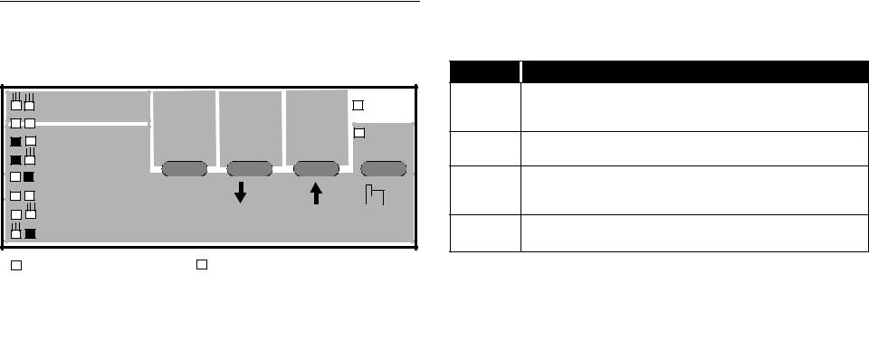
4 switches and 4 LEDs are on the panel as shown below.
Tear Off |
Tear Off |
LF/FF |
Load/Eject |
Paper Out |
Draft |
|
|
|
Pause |
|
|
|
|
|
Draft Condensed |
|
|
|
|
Roman |
|
|
|
|
Roman Condensed |
Font |
Micro Adjust |
3 sec |
|
Sans serif |
|
|
|
|
Sans serif Condensed |
|
|
|
|
: LED On |
|
|
: LED Blinks |
|
: LED Off |
|
|
|
Figure 1-7. Control Panel
1.4.1.1 Switches
Operation in normal mode
In normal mode, pressing panel switches executes following function;
Table 1-17. Operation in Normal Mode
Switch Function
-Alternates printing and non-printing status.
Pause -Enables Micro Adjustment function and Font selection, holding it down for 3 seconds.
Load/Eject
-Loads or ejects paper.
-Execute micro feed forward, when this function is enabled.
-Executes line feed, pressing it shortly.
LF/FF -Executes form feed, holding it down for a few seconds. -Executes micro feed backward, when this function is enabled.
-Advances continuous paper to the Tear-off position.
Tear Off
-Select font, when this function is enabled.
Operation at power on
Turning the printer on while pressing panel switches executes the functions below;
Table 1-18. Operation at Power On
Switch |
|
Function |
|
|
|
Load/Eject |
|
NLQ self test |
|
|
|
LF/FF |
|
Draft self test |
|
|
|
Tear Off |
|
Default setting |
|
|
|
Load/Eject & LF/FF |
|
Data dump |
|
|
|
Load/Eject & LF/FF & Pause |
|
Clear EEPROM |
|
|
|
Tear Off & Load/Eject & LF/FF |
|
Clear EEPROM for Diving Line count for ribbon |
|
change timing. |
|
|
|
|
|
|
|
Pause |
|
Bi-d adjustment |
|
|
|
The others |
|
Not available |
|
|
|
Product Description |
Operation |
24 |

LX-300+ |
Revision A |
Operation in default setting mode
The following switches are used in default setting mode;
|
Table 1-19. Operation at Power On |
||
|
|
|
|
Switch |
|
|
Function |
|
|
|
|
Tear Off |
|
|
Changes the setting. |
|
|
|
|
LF/FF |
|
|
Selects the Menu. |
|
|
|
|
The others |
|
|
Not available. |
|
|
|
|
1.4.1.2 LED
Indication in normal mode
*3 Font (Green)
-The status of Font selection is displayed by 2 Font LEDs when continuous paper is out of the Tear-off position.
-Both LEDs blink when continuous paper is in the Tear-off position.: Draft
: Draft Condensed: Roman
: Roman Condensed: Sans serif
: Sans serif Condensed: Tear Off
( : LED On, : LED Off, : LED Blinks)
1.4.1.3 Buzzer
Table 1-20. Indication in normal mode
LED |
|
Pause*1 |
|
Paper |
|
Font |
|
|
|
|
|||
Printer Status |
|
|
Out*2 |
|
||
|
|
|
|
|
||
|
|
|
|
|
|
|
|
|
|
|
|
|
|
Pause |
|
On |
|
--- |
|
--- |
|
|
|
|
|
|
|
Paper out error |
|
On |
|
On |
|
--- |
|
|
|
|
|
|
|
Release lever error |
|
On |
|
--- |
|
--- |
|
|
|
|
|
|
|
Paper eject warning |
|
On |
|
Blink |
|
--- |
|
|
|
|
|
|
|
Micro Adjust |
|
Blink |
|
--- |
|
--- |
|
|
|
|
|
|
|
Tear off |
|
--- |
|
--- |
|
*3 |
|
|
|
|
|
|
|
Font selection |
|
--- |
|
--- |
|
*3 |
|
|
|
|
|
|
|
Fatal error |
|
Blink |
|
Blink |
|
Blink |
|
|
|
|
|
|
|
Paper out error: |
Beeper sounds (...)* |
Release lever operation: |
Beeper sounds(-----)* |
Illegal panel operation: |
Beeper sounds (.)* |
*The description (.) and (-) in the above shows how the beeper sounds. (.): Beeper sounds approx. 100ms and interval is approx. 100ms.
(-): Beeper sounds approx. 500ms and interval is approx. 100ms.
*1 Pause (Orange)
-It is on when the printer is paused, and it is off when the printer is not paused.
-It blinks when Micro Adjust is enabled.
*2 Paper Out (Red)
-It is on when the printer is in the Paper out status, and it is off when the printer is out of this status.
Product Description |
Operation |
25 |
LX-300+ |
Revision A |
1.4.2 Functions
1.4.2.1 Usual Operation
Pause
-This switch alternates printer activity between printing and nonprinting.
-By holding it down over 3 seconds when the printer is in the stand by state, the Micro Adjust function is enabled. By pressing it again, this function is disabled.
Load/Eject
-Pressing it loads out sheet or continuous paper when the printer is out of paper.
-Pressing it ejects out sheet to the stacker or continuous paper to the paper park.
LF/FF
-Pressing it shortly executes line feed.
-Holding it down for a few seconds executes form feed when continuous paper is used, or ejects cut sheet to the stacker when cut sheet is used.
Tear Off
-When continuous paper is used, pressing it moves a page to the Tear-off position. And pressing it again moves a next page to the TOF position.
Font
-Pressing it selects one of the following fonts when Micro Adjust is enabled;
Draft, Draft Condensed, Roman, Roman Condensed, Sans serif, Sans serif Condensed
Micro Adjust
-Micro Adjust ↓ / ↑ switches is effective when the Micro Adjust
function is enabled by Pause switch.
-Pressing the Micro Adjust ↓ / ↑ switches executes micro feed backward and forward by 0.118 mm (1/216 inch).
-The TOF adjustment is enabled in the TOF position after loading, and the Tear-off adjustment is enabled in the Tear-off position.
1.4.2.2 Operation at Power-on
Self test
Prints the self test pattern. To cancel it, make printer pause and turn off the power.
Default setting
Starts the default setting mode. See 1.4.2.3 "Default Setting".
Data Dump
Starts the data dump mode, in which all the input data are printed as hexadecimal numbers and corresponding characters.
Clear EEPROM
Resets the printer to the factory default setting, which is not always proper setting for each market demand.
(i.e. This function is for emergency.)
Clear Areal EEPROM data except 00H to 1FH.
Clear EEPROM for Driving Line count for ribbon change timing. Resets the diving Line count for ribbon change timing.
Bi-d adjustment
Starts the Bi-d adjustment mode. See 1.4.2.4 "Bi-d. Adjustment".
Demonstration Not available.
1.4.2.3 Default Setting
There are some parameters that can be changed by users and will be referred at the time of initialization of the printer.
Setting mode
1.Enters the Default setting mode.
The method of selecting language for “Usage of this mode” is printed.
2.Select language for “Usage of this mode” by LF/FF button.
Font LEDs show the language for “Usage of this mode” that is currently selected.
This section will be advanced one by one as the button is pressed and the On/Off/Blink/2-Blink of those three LEDs will also be changed according to the selection.
Product Description |
Operation |
26 |

LX-300+ |
Revision A |
3.Press Tear Off button.
The current setting and the “Usage of this mode” by selected language will be printed on the paper set in the paper path at that time.
A print sample is shown in appendix A.
4.Select Menu by Tear Off button.
Font LEDs show the menu which is selected at that time. The selection will be advanced one by one as the button is pressed and the combination of those three LEDs status of On/Off/Blink/2-Blinks will be changed according to the selection.
5.Select setting value by LF/FF button.
Tear Off/ Bin LEDs and Paper Out LED show that menu’s value by status of On/Off/Blink/2-Blinks. That value can be changed by pressing Tear Off/ Bin button and the LEDs status of On/Off/Blink/2-Blinks will be changed as the button is pressed.
6.When LF/FF button is pressed, the printer memorize the last setting value.
7.Repeat (4) to (6).
The other items can be changed in the same manner.
The menu selection will return to the first menu after the last menu selection is over.
8.Turn the printer off.
The setting is stored into non-volatile memory.
|
Table 1-21. Setting Menu |
||
|
|
|
|
Item |
|
|
Setting / Value *2 |
|
|
|
|
|
|
|
3 inch, 3.5 inch, 4 inch, 5.5 inch, 6 inch, 7 inch, |
Page length for tractor |
|
|
8 inch, 8.5 inch, 11 inch, 70/6 inch, 12 inch, 14 inch, |
|
|
|
17 inch |
|
|
|
|
Skip over perforation |
|
|
OFF, ON |
|
|
|
|
Auto tear off |
|
|
OFF, ON |
|
|
|
|
Auto line feed |
|
|
OFF, ON |
|
|
|
|
Print direction |
|
|
Bi-d., Uni-d., Auto |
|
|
|
|
Software |
|
|
ESC/P2, IBM 2390 Plus |
|
|
|
|
0 slash |
|
|
OFF, ON |
|
|
|
|
Table 1-21. Setting Menu |
||
|
|
|
Item |
|
Setting / Value *2 |
|
|
|
High speed draft |
|
OFF, ON |
|
|
|
I/F mode |
|
Auto, Parallel, Option |
|
|
|
Auto I/F wait time |
|
10 seconds, 30 seconds |
|
|
|
Parallel I/F bidirectional |
|
OFF, ON |
mode |
|
|
|
|
|
|
|
|
Packet mode |
|
Auto, OFF |
|
|
|
Auto CR (IBM 2390 Plus) |
|
OFF, ON |
|
|
|
A.G.M. (IBM 2390 Plus) |
|
OFF, ON |
|
|
|
Character table |
|
Software version |
|
|
Italic, PC437, PC850, PC860, PC863, PC865, PC861, |
|
|
BARASCII, Abicomp, Roman8, ISO Latin 1, PC858, |
|
|
ISO 8859-15 |
|
|
|
|
|
NLSP version |
|
|
Italic, PC437, PC850, PC437, Greek, PC853, PC855, |
|
|
PC852, PC857, PC864, PC866, PC869, MAZOWIA, |
|
|
Code MJK, ISO 8859-7, ISO Latin 1T, Bulgaria, |
|
|
PC774, Estonia, ISO 8859-2, PC 866 LAT., PC |
|
|
866UKR, PC APTEC, PC708, PC720, PCAR 864, |
|
|
PC860, PC865, PC861, PC863, BRASCII, Abicomp, |
|
|
Roman8, ISO Latin 1, PC858, ISO 8859-15, PC771 |
|
|
|
International character set |
|
Italic U.S.A., Italic France, Italic Germany, Italic, |
|
U.K., Italic Denmark 1, Italic Sweden, Italic Italy, |
|
for Italic table |
|
Italic Spain 1 |
|
|
|
|
|
|
Manual feed wait time |
|
1 second, 1.5 seconds, 2 seconds, 3 seconds |
|
|
|
Buzzer |
|
OFF, ON |
|
|
|
Auto CR (IBM 2380 Plus)*1 |
|
OFF, ON |
IBM character table *1 |
|
Table2, Table1 |
NOTE: *1: This setting is effective when IBM 2380 Plus emulation is selected.
NOTE: Setting with underline mean the standard factory settings.
Product Description |
Operation |
27 |
LX-300+ |
Revision A |
1.4.2.4 Bi-d. Adjustment
Bi-d. adjustment can be adjusted by users. Bi-d. adjustment method is as follows.
1.Turning the printer on while pressing Pause switch. The guide to adjust Bi-d alignment in this mode and the first alignment pattern will be printed.
2.Select the most closely aligned number by pressing LF/FF (↓) and Load/ Eject (↑) switches.
Font LEDs and Pause LED show the pattern number which is selected at that time. The selection is advanced one by one as the switch is pressed, and the combination of On/Off/Blink of those three LEDs is also changed according to the selection.
3.Fix the selected number by pressing Tear Off switch.
Selected number is fixed and the next alignment pattern is printed.
4.Repeat step 2 to 3 until finishing Bi-d adjustment for NLQ mode. Following adjustment is executed.
-Bi-d. adjustment for high speed draft mode
-Bi-d. adjustment for draft mode
-Bi-d. adjustment for NLQ mode
5.Turn the printer off.
The setting is stored into non-volatile memory.
1.4.3 Errors
Paper out error:
When the printer fails to feed a sheet, it goes a paper out error.
Release lever error:
When release lever position is wrong, it goes a release lever error.
Fatal errors:
Carriage control error and Power supply voltage error.
Product Description |
Operation |
28 |

LX-300+ |
Revision A |
1.5 Control codes
1.5.1 ESC/P2
Table 1-22. ESC/P2
Classification |
|
Operation |
|
Command |
|
|
|
|
|
General Operation |
|
Initialize Printer |
|
ESC@ |
|
|
|
|
|
|
|
Unidirectional Printing |
|
ESC U |
|
|
|
|
|
|
|
CSF Mode Control |
|
ESC EM |
|
|
|
|
|
Paper feeding |
|
Form Feed |
|
FF |
|
|
|
|
|
|
|
Line Feed |
|
LF |
|
|
|
|
|
|
|
Line Spacing |
|
ESC 0, ESC 2, ESC3, ESC A |
|
|
|
|
|
|
|
Carriage Return |
|
CR |
|
|
|
|
|
Page format |
|
Page Length |
|
ESC C, ESC C0, ESC (C |
|
|
|
|
|
|
|
Left / Right Margin |
|
ESC Q, ESC1 |
|
|
|
|
|
|
|
Top / Bottom Margin |
|
ESC N, ESC O, ESC (c |
|
|
|
|
|
|
|
Define Unit |
|
ESC (U |
|
|
|
|
|
Print position motion |
|
Horizontal Print Position |
|
ESC$, ESC¥ |
|
|
|
|
|
|
|
Vertical Print Position |
|
ESC (V, ESC (v |
|
|
|
|
|
|
|
Tab Horizontally |
|
ESC D, HT |
|
|
|
|
|
|
|
Tab Vertically |
|
ESC B, VT |
|
|
|
|
|
|
|
Advance paper |
|
ESC J |
|
|
|
|
|
Font selection |
|
Typeface |
|
ESC k, ESC x, ESC y |
|
|
|
|
|
|
|
Pitch |
|
ESC P, ESC M, ESC g, ESC p |
|
|
|
|
|
|
|
Italic Font |
|
ESC 4, ESC 5 |
|
|
|
|
|
|
|
Bold Font |
|
ESC E, ESC F |
|
|
|
|
|
|
|
Master Select |
|
ESC! |
|
|
|
|
|
Table 1-22. ESC/P2
Classification |
|
Operation |
|
Command |
|
|
|
|
|
Font enhancement |
|
Double-Width |
|
ESC W, DC4, SO |
|
|
|
|
|
|
|
Condensed |
|
DC2, SI |
|
|
|
|
|
|
|
Double-height |
|
ESC w |
|
|
|
|
|
|
|
Double-Strike |
|
ESC G, ESC H |
|
|
|
|
|
|
|
Super-/ Subscript |
|
ESC T, ESC S |
|
|
|
|
|
|
|
Underline |
|
ESC- |
|
|
|
|
|
Spacing |
|
Intercharacter Space |
|
ESC Space |
|
|
|
|
|
Character handling |
|
Character Table |
|
ESC t, ESC (t |
|
|
|
|
|
|
|
International Character |
|
ESC R |
|
|
|
|
|
|
|
User-Defined Characters |
|
ESC%, ESC &, ESC: |
|
|
|
|
|
|
|
Control code selection |
|
ESC1 |
|
|
|
|
|
|
|
Upper Control Codes |
|
ESC6, ESC7 |
|
|
|
|
|
|
|
8 pin Bit Image |
|
ESC K, ESC L, ESC Y, ESC Z, |
Bit image |
|
|
ESC* |
|
|
|
|
||
|
|
|
|
|
|
|
9 pin Bit Image |
|
ESC ^ |
|
|
|
|
|
Printing color |
|
Select color |
|
ESC r |
|
|
|
|
|
Bar code |
|
Bar code |
|
ESC (B |
|
|
|
|
|
Production |
|
EEPOM write, etc. |
|
ESC| |
|
|
|
|
|
Product Description |
Control codes |
29 |

LX-300+ |
Revision A |
1.5.2 IBM 2390 Plus Emulation
Table 1-23. IBM 2390 Plus emulation
Classification |
|
Operation |
|
Command |
|
|
|
|
|
General Operation |
|
Nop |
|
NUL, DC3 |
|
|
|
|
|
|
|
Off Line |
|
ESC j |
|
|
|
|
|
|
|
Buzzer |
|
BEL |
|
|
|
|
|
|
|
Cancellation |
|
CAN |
|
|
|
|
|
|
|
Select / Deselect |
|
DC1, ESC Q |
|
|
|
|
|
|
|
Initialize Printer |
|
ESC [K |
|
|
|
|
|
|
|
Unidirectional Printing |
|
ESC U |
|
|
|
|
|
|
|
Select Auto Sheet Feeder |
|
ESC [F |
|
|
|
|
|
Paper feeding |
|
Form Feed |
|
FF |
|
|
|
|
|
|
|
Line Feed, |
|
LF, ESC5 |
|
|
Auto Line Feed |
|
|
|
|
|
|
|
|
|
|
|
|
|
|
Line Spacing |
|
ESC A, ESC 0, ESC 1, ESC 2, |
|
|
|
ESC3 |
|
|
|
|
|
|
|
|
|
|
|
|
|
Carriage Return |
|
CR |
|
|
|
|
|
|
|
Reverse Line Feed |
|
ESC] |
|
|
|
|
|
Page format |
|
Page Length |
|
ESC C, ESC C0 |
|
|
|
|
|
|
|
Left / Right Margin |
|
ESC X |
|
|
|
|
|
|
|
Skip Over Perforation |
|
ESC N, ESC O |
|
|
|
|
|
|
|
Set TOF |
|
ESC 4 |
|
|
|
|
|
Print position motion |
|
Horizontal Print Position |
|
ESC d |
|
|
|
|
|
|
|
Initialize Tab Position |
|
ESC R |
|
|
|
|
|
|
|
Tab Horizontally |
|
ESC D, HT |
|
|
|
|
|
|
|
Tab Vertically |
|
ESC B, VT |
|
|
|
|
|
|
|
Advance paper |
|
ESC J |
|
|
|
|
|
Table 1-23. IBM 2390 Plus emulation
Classification |
|
Operation |
|
Command |
|
|
|
|
|
Font selection |
|
Pitch |
|
DC 2, ESC P, ESC: |
|
|
|
|
|
|
|
Bold Font |
|
ESC E, ESC F |
|
|
|
|
|
|
|
Master Select |
|
ESC I |
|
|
|
|
|
|
|
Print Quality |
|
ESC [d |
|
|
|
|
|
|
|
Select Font and Pitch |
|
ESC [I |
|
|
|
|
|
Font enhancement |
|
Double-Width |
|
DC4, SO, ESC SO, ESC W |
|
|
|
|
|
|
|
Enlarge and Life Space |
|
ESC [@ |
|
|
|
|
|
|
|
Condensed |
|
SI, ESC SI |
|
|
|
|
|
|
|
Double-Strike |
|
ESC G, ESC H |
|
|
|
|
|
|
|
Super-/ Subscript |
|
ESC T, ESC S |
|
|
|
|
|
|
|
Underline |
|
ESC - |
|
|
|
|
|
|
|
Line / Score |
|
ESC_ |
|
|
|
|
|
Spacing |
|
Back Space |
|
BS |
|
|
|
|
|
|
|
Space |
|
SP |
|
|
|
|
|
|
|
Define Unit |
|
ESC [¥ |
|
|
|
|
|
Character handling |
|
Character Table |
|
ESC 6, ESC 7, ESC [T |
|
|
|
|
|
|
|
Print Data as Characters |
|
ESC ^, ESC¥ |
|
|
|
|
|
Bit image |
|
Bit Image |
|
ESC K, ESC L, ESC Y, ESC Z |
|
|
|
|
|
Bar code |
|
Set up Bar code |
|
ESC [f |
|
|
|
|
|
|
|
Transfer Bar code |
|
ESC [p |
|
|
|
|
|
Download |
|
Download |
|
ESC=(only Draft mode) |
|
|
|
|
|
Product Description |
Control codes |
30 |
Loading...