


 Loading...
EPSON G20-A04C, G10-654SR, G10-851S, G20-854C, G10-654C User Manual
...SCARA ROBOT
G10 / G20 series
MANIPULATOR MANUAL
Rev.10 |
EM111R2122F |
MANIPULATOR MANUAL |
G10 / G20 series Rev.10 |
SCARA ROBOT
G10 / G20 series Manipulator Manual
Rev.10
Copyright © 2007-2011 SEIKO EPSON CORPORATION. All rights reserved.
G10 / G20 Rev.10 |
i |
FOREWORD
Thank you for purchasing our robot products.
This manual contains the information necessary for the correct use of the manipulator. Please carefully read this manual and other related manuals before installing the robot system.
Keep this manual handy for easy access at all times.
WARRANTY
The Manipulator and its optional parts are shipped to our customers only after being subjected to the strictest quality controls, tests, and inspections to certify its compliance with our high performance standards.
Product malfunctions resulting from normal handling or operation will be repaired free of charge during the normal warranty period. (Please ask your Regional Sales Office for warranty period information.)
However, customers will be charged for repairs in the following cases (even if they occur during the warranty period):
1.Damage or malfunction caused by improper use which is not described in the manual, or careless use.
2.Malfunctions caused by customers’ unauthorized disassembly.
3.Damage due to improper adjustments or unauthorized repair attempts.
4.Damage caused by natural disasters such as earthquake, flood, etc.
Warnings, Cautions, Usage:
1.If the Manipulator or associated equipment is used outside of the usage conditions and product specifications described in the manuals, this warranty is void.
2.If you do not follow the WARNINGS and CAUTIONS in this manual, we cannot be responsible for any malfunction or accident, even if the result is injury or death.
3.We cannot foresee all possible dangers and consequences. Therefore, this manual cannot warn the user of all possible hazards.
ii |
G10 / G20 Rev.10 |

TRADEMARKS
Microsoft, Windows, and Windows logo are either registered trademarks or trademarks of Microsoft Corporation in the United States and/or other countries. Other brand and product names are trademarks or registered trademarks of the respective holders.
NOTICE
No part of this manual may be copied or reproduced without authorization. The contents of this manual are subject to change without notice.
Please notify us if you should find any errors in this manual or if you have any comments regarding its contents.
INQUIRIES
Contact the following service center for robot repairs, inspections or adjustments.
If service center information is not indicated below, please contact the supplier office for your region.
Please prepare the following items before you contact us.
-Your controller model and its serial number
-Your manipulator model and its serial number
-Software and its version in your robot system
-A description of the problem
SERVICE CENTER
G10 / G20 Rev.10 |
iii |
MANUFACTURER & SUPPLIER
Japan & Others |
SEIKO EPSON CORPORATION |
|
|
Suwa Minami Plant |
|
|
Factory Automation Systems Dept. |
|
|
1010 Fujimi, Fujimi-machi, |
|
|
Suwa-gun, Nagano, 399-0295 |
|
|
JAPAN |
|
|
TEL |
: +81-(0)266-61-1802 |
|
FAX |
: +81-(0)266-61-1846 |
SUPPLIERS
North & South America EPSON AMERICA, INC.
Factory Automation/Robotics 18300 Central Avenue Carson, CA 90746
USA
TEL : +1-562-290-5900
FAX : +1-562-290-5999 E-MAIL : info@robots.epson.com
Europe |
EPSON DEUTSCHLAND GmbH |
|
|
Factory Automation Division |
|
|
Otto-Hahn-Str.4 |
|
|
D-40670 Meerbusch |
|
|
Germany |
|
|
TEL |
: +49-(0)-2159-538-1391 |
|
FAX |
: +49-(0)-2159-538-3170 |
|
: robot.infos@epson.de |
|
China |
EPSON China Co., Ltd |
|
|
Factory Automation Division |
|
|
7F, Jinbao Building No. 89 Jinbao Street |
|
|
Dongcheng District, Beijing, |
|
|
China, 100005 |
|
|
TEL |
: +86-(0)-10-8522-1199 |
|
FAX |
: +86-(0)-10-8522-1120 |
Taiwan |
EPSON Taiwan Technology & Trading Ltd. |
|
|
Factory Automation Division |
|
|
14F, No.7, Song Ren Road, Taipei 110 |
|
|
Taiwan, ROC |
|
|
TEL |
: +886-(0)-2-8786-6688 |
|
FAX |
: +886-(0)-2-8786-6677 |
iv |
G10 / G20 Rev.10 |

For Customers in the European Union
The crossed out wheeled bin label that can be found on your product indicates that this product and incorporated batteries should not be disposed of via the normal household waste stream. To prevent possible harm to the environment or human health please separate this product and its batteries from other waste streams to ensure that it can be recycled in an environmentally sound manner. For more details on available collection facilities please contact your local government office or the retailer where you purchased this product. Use of the chemical symbols Pb, Cd or Hg indicates if these metals are used in the battery.
This information only applies to customers in the European Union, according to DIRECTIVE 2006/66/EC OF THE EUROPEAN PARLIAMENT AND OF THE COUNCIL OF 6 September 2006 on batteries and accumulators and waste batteries and accumulators and repealing Directive 91/157/EEC and legislation transposing and implementing it into the various national legal systems.
For other countries, please contact your local government to investigate the possibility of recycling your product.
The battery removal/replacement procedure is described in the following manuals:
Controller manual / Manipulator manual (Maintenance section)
G10 / G20 Rev.10 |
v |

Before Reading This Manual
This section describes what you should know before reading this manual.
Structure of Control System
The G10 / G20 series Manipulators can be used with the following combinations of Controllers and software.
The operating methods and descriptions are different depending on which software you are using. The following icons are put beside appropriate text as necessary. Use the descriptions that pertain to the software you are using.
Controller |
Software |
RC180 |
EPSON RC+ 5.0 |
|
|
RC620 |
EPSON RC+ 6.0 |
|
|
For details on commands, refer to User’s Guide or “On-line help”.
Turning ON/OFF Controller
When you see the instruction “Turn ON/OFF the Controller” in this manual, be sure to turn ON/OFF all the hardware components. For the Controller composition, refer to the table above.
Shape of Motors
The shape of the motors used for the Manipulator that you are using may be different from the shape of the motors described in this manual because of the specifications.
Setting by Using Software
This manual contains setting procedures by using software. They are marked with the following icon.
EPSON
RC+
vi |
G10 / G20 Rev.10 |

TABLE OF CONTENTS
Table of Contents
Before Reading This Manual............................................................................ |
v |
Setup & Operation
1.Safety ···························································································· 3
1.1 |
Conventions ........................................................................................... |
3 |
1.2 |
Design and Installation Safety ............................................................... |
4 |
1.3 |
Operation Safety .................................................................................... |
5 |
1.4 |
Emergency Stop .................................................................................... |
6 |
1.5 |
Emergency Movement Without Drive Power ......................................... |
7 |
1.6 |
Manipulator Labels ................................................................................. |
8 |
2.Specifications ············································································ 10
2.1 |
Features of G10 series and G20 series Manipulators .......................... |
10 |
|
2.2 |
Model Number and Model Differences ................................................. |
11 |
|
2.3 |
Part Names and Outer Dimensions ..................................................... |
12 |
|
|
2.3.1 |
Table Top Mounting ........................................................................ |
12 |
|
2.3.2 |
Wall Mounting ................................................................................. |
18 |
|
2.3.3 |
Ceiling Mounting ............................................................................. |
24 |
|
2.3.4 G10-65***/G10-85***: For S/N1**** or later .................................... |
30 |
|
2.4 |
Specifications ....................................................................................... |
31 |
|
2.5 |
How to Set the Model ........................................................................... |
34 |
|
3.Environments and Installation ·················································· 35
3.1 |
Environmental Conditions .................................................................... |
35 |
|
3.2 |
Base Table ........................................................................................... |
37 |
|
3.3 |
Mounting Dimensions .......................................................................... |
38 |
|
3.4 |
Unpacking and Transportation ............................................................. |
41 |
|
|
3.4.1 |
Precautions for Transportation ....................................................... |
41 |
|
3.4.2 |
Transportation ................................................................................. |
42 |
3.5 |
Installation ............................................................................................ |
42 |
|
|
3.5.1 |
Table Top Mounting ........................................................................ |
43 |
|
3.5.2 |
Wall Mounting ................................................................................. |
44 |
|
3.5.3 |
Ceiling Mounting ............................................................................. |
45 |
|
3.5.4 |
Cleanroom-model ........................................................................... |
46 |
|
3.5.5 |
Protected-model ............................................................................. |
46 |
3.6 |
Connecting the Cables ......................................................................... |
47 |
|
3.7 |
User Wires and Pneumatic Tubes ....................................................... |
49 |
|
3.8 |
Relocation and Storage ........................................................................ |
51 |
|
|
3.8.1 Precautions for Relocation and Storage ......................................... |
51 |
|
|
3.8.2 |
Table Top Mounting ........................................................................ |
52 |
|
3.8.3 |
Wall Mounting ................................................................................. |
53 |
|
3.8.4 |
Ceiling Mounting ............................................................................. |
54 |
G10 / G20 Rev.10 |
|
|
vii |

TABLE OF CONTENTS
4. Setting of End Effectors ··························································· 55
4.1 |
Attaching an End Effector .................................................................... |
55 |
|
4.2 |
Attaching Cameras and Valves ........................................................... |
57 |
|
4.3 |
Weight and Inertia Settings ................................................................. |
58 |
|
|
4.3.1 |
Weight Setting ................................................................................ |
58 |
|
4.3.2 |
Inertia Setting ................................................................................. |
62 |
4.4 |
Precautions for Auto Acceleration/Deceleration of Joint #3 ................. |
67 |
|
5.Motion Range ············································································ 68
5.1 |
Motion Range Setting by Pulse Range (for All Joints) ......................... |
69 |
|
5.1.1 Max. Pulse Range of Joint #1 ........................................................ |
69 |
|
5.1.2 Max. Pulse Range of Joint #2 ........................................................ |
70 |
|
5.1.3 Max. Pulse Range of Joint #3 ........................................................ |
71 |
|
5.1.4 Max. Pulse Range of Joint #4 ........................................................ |
71 |
5.2 |
Motion Range Setting by Mechanical Stops ........................................ |
72 |
|
5.2.1 Setting the Mechanical Stops of Joints #1 and #2 ......................... |
73 |
|
5.2.2 Setting the Mechanical Stop of Joint #3 ......................................... |
76 |
5.3Setting the Cartesian (Rectangular) Range in the XY Coordinate
System of the Manipulator (for Joints #1 and #2) ............................... |
78 |
5.4 Standard Motion Range ....................................................................... |
79 |
Maintenance
1.Safety Maintenance ··································································· 85
2.General Maintenance ································································ 86
2.1 |
Schedule for Maintenance Inspection ................................................. |
86 |
|
2.2 |
Inspection Point ................................................................................... |
87 |
|
|
2.2.1 Inspection While the Power is OFF (Manipulator is not operating) . 87 |
||
|
2.2.2 Inspection While the Power is ON (Manipulator is operating) ......... |
87 |
|
2.3 |
Greasing .............................................................................................. |
88 |
|
2.4 |
Tightening Hexagon Socket Head Cap Bolts ...................................... |
89 |
|
2.5 |
Matching Origins ................................................................................. |
91 |
|
2.6 |
Layout of Maintenance Parts ............................................................... |
91 |
|
|
2.6.1 |
Table Top Mounting ........................................................................ |
91 |
|
2.6.2 |
Wall Mounting ................................................................................ |
93 |
|
2.6.3 |
Ceiling Mounting ............................................................................ |
95 |
|
2.6.4 G10-65***: For S/N1**** or later .................................................... |
97 |
|
3.Cover ·························································································· 98
3.1 |
Arm Top Cover .................................................................................. |
100 |
|
3.2 |
Arm Bottom Cover ............................................................................. |
102 |
|
3.3 |
Arm #1 Cover .................................................................................... |
103 |
|
|
3.3.1 |
G10/G20-***S*, G10/G20-***C* ................................................... |
103 |
|
3.3.2 |
G10/G20-***D*, P* ....................................................................... |
104 |
viii |
|
|
G10 / G20 Rev.10 |
|
|
TABLE OF CONTENTS |
3.4 |
Connector Plate ................................................................................. |
105 |
3.5 |
Connector Sub Plate .......................................................................... |
106 |
3.6 |
User Plate .......................................................................................... |
107 |
3.7 |
Maintenance Plate ............................................................................. |
107 |
3.8 |
Base Bottom Cover ............................................................................ |
108 |
4.Cable Unit ················································································· 109
4.1 |
Replacing Cable Unit ......................................................................... |
110 |
|
4.2 |
Wiring Diagrams ................................................................................ |
122 |
|
|
4.2.1 |
Signal Cable ................................................................................. |
122 |
|
4.2.2 |
Power Cable ................................................................................. |
123 |
|
4.2.3 |
User Cable .................................................................................... |
124 |
5.Arm #1 ······················································································ 125
5.1 |
Replacing Joint #1 |
Motor ................................................................... |
126 |
5.2 |
Replacing Joint #1 |
Reduction Gear Unit ............................................ |
128 |
6.Arm #2 ······················································································ 131
6.1 |
Replacing Joint #2 |
Motor ................................................................... |
132 |
6.2 |
Replacing Joint #2 |
Reduction Gear Unit ............................................ |
137 |
7.Arm #3 ······················································································ 140
7.1 |
Replacing Joint #3 Motor ................................................................... |
141 |
|
7.2 |
Replacing the Timing Belt .................................................................. |
145 |
|
|
7.2.1 |
G10 ............................................................................................... |
146 |
|
7.2.2 |
G20 ............................................................................................... |
150 |
7.3 |
Replacing the Brake ........................................................................... |
151 |
|
8.Arm #4 ······················································································ 153
8.1 |
Replacing Joint #4 Motor ................................................................... |
154 |
|
|
8.1.1 |
G10 ............................................................................................... |
154 |
|
8.1.2 |
G20 ............................................................................................... |
158 |
8.2 |
Replacing the Timing Belt .................................................................. |
160 |
|
|
8.2.1 |
G10 ............................................................................................... |
161 |
|
8.2.2 |
G20 ............................................................................................... |
165 |
8.3 |
Replacing the Brake ........................................................................... |
170 |
|
8.4 |
Replacing the Reduction Gear Unit .................................................... |
173 |
|
|
8.4.1 |
G10 ............................................................................................... |
174 |
|
8.4.2 |
G20 ............................................................................................... |
175 |
9.Bellows ····················································································· 177
G10 / G20 Rev.10 |
ix |

TABLE OF CONTENTS
10.Ball Screw Spline Unit ························································· 180
10.1 |
Greasing the Ball Screw Spline Unit ................................................ |
181 |
|
|
10.1.1 |
Standard-model ........................................................................... |
181 |
|
10.1.2 |
Cleanroom-model / Protected-model........................................... |
182 |
10.2 |
Replacing the Ball Screw Spline Unit .............................................. |
184 |
|
|
10.2.1 |
G10 .............................................................................................. |
184 |
|
10.2.2 |
G20 .............................................................................................. |
191 |
11.Lithium Battery ······································································ 196
11.1 |
Replacing the Battery Unit (Lithium Battery) .................................... |
197 |
11.2 |
Replacing the Battery Board ............................................................ |
199 |
12.LED Lamp ·············································································· 201
13.Radiating Unit ········································································ 203
14.Calibration ············································································· 205
14.1 |
About Calibration ............................................................................. |
205 |
14.2 |
Calibration Procedure ...................................................................... |
206 |
14.3 |
Accurate Calibration of Joint #2 ....................................................... |
216 |
14.4 |
Calibration Procedure without using Calibration Wizard .................. |
218 |
15.Maintenance Parts List ························································· 222
15.1 |
Common Parts ................................................................................ |
222 |
15.2 |
Parts by Environment Model ........................................................... |
224 |
x |
G10 / G20 Rev.10 |

Setup & Operation
This volume contains information for setup and operation of the G10 / G20 series Manipulators.
Please read this volume thoroughly before setting up and operating the Manipulators.

Setup & Operation 1. Safety
1.Safety
Installation and transportation of robots and robotic equipment shall be performed by qualified personnel and should conform to all national and local codes. Please read this manual and other related manuals before installing the robot system or before connecting cables.
Keep this manual handy for easy access at all times.
1.1Conventions
Important safety considerations are indicated throughout the manual by the following symbols. Be sure to read the descriptions shown with each symbol.
|
This symbol indicates that a danger of possible serious |
|
injury or death exists if the associated instructions are not |
WARNING |
followed properly. |
|
|
|
|
|
This symbol indicates that a danger of possible serious |
|
injury or death caused by electric shock exists if the |
WARNING |
associated instructions are not followed properly. |
|
|
|
|
|
This symbol indicates that a danger of possible harm to |
|
people or physical damage to equipment and facilities |
|
exists if the associated instructions are not followed |
CAUTION |
properly. |
|
|
G10 / G20 Rev.10 |
3 |

Setup & Operation 1. Safety
1.2Design and Installation Safety
Only trained personnel should design and install the robot system. Trained personnel are defined as those who have taken robot system training and maintenance training classes held by the manufacturer, dealer, or local representative company, or those who understand the manuals thoroughly and have the same knowledge and skill level as those who have completed the training courses.
To ensure safety, a safeguard must be installed for the robot system. For details on the safeguard, refer to the Installation and Design Precautions in the Safety chapter of the EPSON RC+ User’s Guide.
The following items are safety precautions for design personnel:
■Personnel who design and/or construct the robot system with this product must read the Safety chapter in the EPSON RC+ User’s Guide to understand the safety requirements before designing and/or constructing the robot system. Designing and/or constructing the robot system without understanding the safety requirements is extremely hazardous, may result in serious bodily injury and/or severe equipment damage to the robot system, and may cause serious safety problems.
■The Manipulator and the Controller must be used within the environmental conditions described in their respective manuals. This product has been
WARNING |
designed and manufactured strictly for use in a normal indoor environment. |
|
Using the product in an environment that exceeds the specified environmental |
||
|
||
|
conditions may not only shorten the life cycle of the product but may also cause |
|
|
serious safety problems. |
■The robot system must be used within the installation requirements described in the manuals. Using the robot system outside of the installation requirements may not only shorten the life cycle of the product but also cause serious safety problems.
Further precautions for installation are mentioned in the chapter Setup & Operation: 3. Environments and Installation. Please read this chapter carefully to understand safe installation procedures before installing the robots and robotic equipment.
4 |
G10 / G20 Rev.10 |
Setup & Operation 1. Safety
1.3Operation Safety
The following items are safety precautions for qualified Operator personnel:
■Please carefully read the Safety-related Requirements in the Safety chapter of the EPSON RC+ User’s Guide before operating the robot system. Operating the robot system without understanding the safety requirements is extremely hazardous and may result in serious bodily injury and/or severe equipment damage to the robot system.
■Do not enter the operating area of the Manipulator while the power to the robot system is turned ON. Entering the operating area with the power ON is extremely hazardous and may cause serious safety problems as the Manipulator may move even if it seems to be stopped.
■Before operating the robot system, make sure that no one is inside the
WARNING |
safeguarded area. The robot system can be operated in the mode for teaching |
|
even when someone is inside the safeguarded area. |
|
The motion of the Manipulator is always in restricted (low speeds and low power) |
|
status to secure the safety of an operator. However, operating the robot system |
|
while someone is inside the safeguarded area is extremely hazardous and may |
|
result in serious safety problems in case that the Manipulator moves |
|
unexpectedly. |
■Immediately press the Emergency Stop switch whenever the Manipulator moves abnormally while the robot system is operated.
■To shut off power to the robot system, pull out the power plug from the power source. Be sure to connect the AC power cable to a power receptacle. DO NOT connect it directly to a factory power source.
■Before performing any replacement procedure, turn OFF the Controller and related equipment, and then pull out the power plug from the power source. Performing any replacement procedure with the power ON is extremely hazardous and may result in electric shock and/or malfunction of the robot
WARNING system.
■Do not insert or pull out the motor connectors while the power to the robot system is turned ON. Inserting or pulling out the motor connectors with the power ON is extremely hazardous and may result in serious bodily injury as the Manipulator may move abnormally, and also may result in electric shock and/or malfunction of the robot system.
■Whenever possible, only one person should operate the robot system. If it is necessary to operate the robot system with more than one person, ensure that all people involved communicate with each other as to what they are doing and take
CAUTION |
all necessary safety precautions. |
G10 / G20 Rev.10 |
5 |
Setup & Operation 1. Safety
1.4Emergency Stop
If the Manipulator moves abnormally during operation, immediately press the Emergency Stop switch. Stops the power supply to the motor, and the arm stops in the shortest distance with the dynamic brake and mechanical brake.
However, avoid pressing the Emergency Stop switch unnecessarily while the Manipulator is running normally. Otherwise, the Manipulator may hit the peripheral equipment since the operating trajectory while the robot system stops is different from that in normal operation.
To place the system in emergency mode during normal operation, press the Emergency Stop switch when the Manipulator is not moving.
Refer to the Controller manual for instructions on how to wire the Emergency Stop switch circuit.
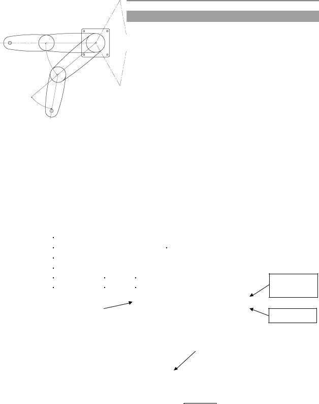
Free running distance in emergency
The operating Manipulator cannot stop immediately after the Emergency Stop switch is pressed.
The free running time/angle/distance of the Manipulator are shown below. However,
remember that the values vary depending on following conditions. |
|
||
Weight of the end effector |
Weight of work piece |
Operating pose |
|
Weight |
Speed |
Accel |
etc. |
Conditions for Measurement
|
|
|
G10 |
G20 |
|
|
|
|
|
|
Accel Setting |
100 |
100 |
|
|
|
|
|
|
|
Speed Setting |
100 |
100 |
|
|
|
|
|
|
|
Load [kg] |
10 |
20 |
|
|
|
|
|
|
|
Weight Setting |
10 |
20 |
|
|
|
|
|
|
|
|
|
|
|
|
Point where the |
|
|
|
|
emergency stop |
|
|
Joint #1 |
|
signal is input |
|
|
|
|
|
|
|
|
Start point of operation
Target point
|
|
|
|
Stop point |
|
|
|
||
|
Joint #2 |
|
|
|
|
|
|
|
|
|
|
|
|
|
|
|
|
||
|
|
|
|
|
|
|
|
||
Controller |
|
|
|
|
RC180 / RC620 |
|
|||
Manipulator |
|
|
G10-65*** |
G10-85*** |
G20-85*** |
G20-A0*** |
|||
Free running |
Joint #1 + Joint #2 |
[sec.] |
0.6 |
0.7 |
1.0 |
1.3 |
|||
time |
Joint #3 |
[sec.] |
0.6 |
0.5 |
0.5 |
0.8 |
|||
Free running |
Joint #1 |
[deg.] |
80 |
70 |
80 |
110 |
|||
Joint #2 |
[deg.] |
70 |
50 |
40 |
50 |
||||
angle |
|||||||||
Joint #1 + Joint #2 |
[deg.] |
110 |
120 |
110 |
160 |
||||
|
|||||||||
Free running |
Joint #3 G10/G20-**1** [mm] |
90 |
80 |
70 |
90 |
||||
distance |
G10/G20-**4** |
|
210 |
160 |
200 |
170 |
|||
6 |
G10 / G20 Rev.10 |
Setup & Operation 1. Safety
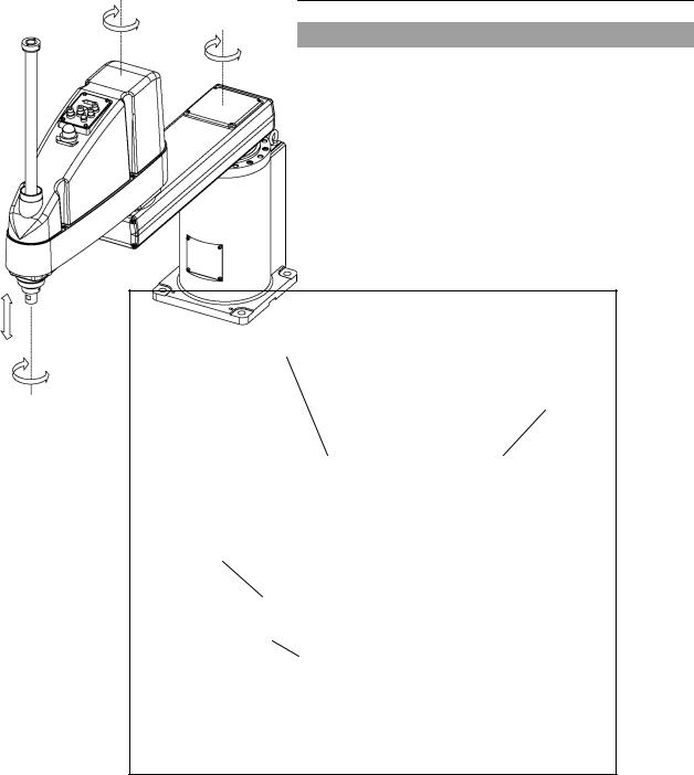
1.5Emergency Movement Without Drive Power
When the system is placed in emergency mode, push the arm or joint of the Manipulator by hand as shown below:
Arm #1 Push the arm by hand. Arm #2 Push the arm by hand.
Joint #3 The joint cannot be moved up/down by hand until the electromagnetic brake applied to the joint has been released. Move the joint up/down while pressing the brake release button switch.
Joint #4 The shaft cannot be rotated by hand until the electromagnetic brake applied to the shaft has been released.
Move the shaft while pressing the brake release button switch.
|
Joint #2 |
Joint #1 |
|
Joint #3 and #4 |
(rotating) |
||
− |
(rotating) |
||
brake release button |
|||
+ |
|
||
|
− |
||
|
|
||
|
|
+ |
Arm #1
Arm #2
 Base
Base
+
Joint #3 |
Shaft |
|
(up and down) |
||
− − |
||
|
||
|
+ |
Joint #4 (rotating)
NOTE
)pressed in emergency mode, the brakes for both Joints #3 and #4 are released simultaneously.
Be careful of the shaft falling and rotating while the brake release button is pressed because the shaft may be lowered by the weight of an end effector.When the brake release button isThe brake release button affects both Joints #3 and #4.
G10 / G20 Rev.10 |
7 |
Setup & Operation 1. Safety
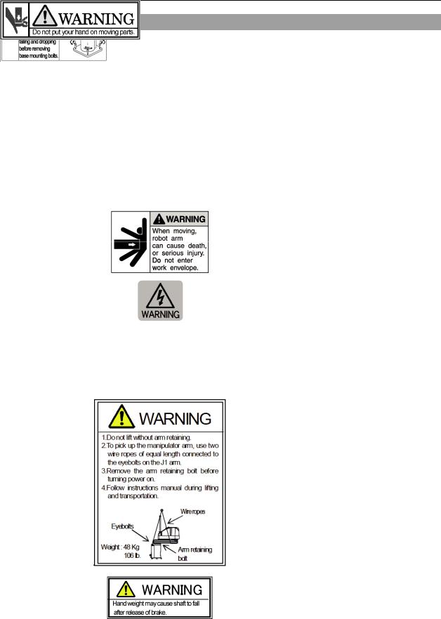
1.6Manipulator Labels
The following labels are attached near the locations of the Manipulator where specific dangers exist.
Be sure to comply with descriptions and warnings on the labels to operate and maintain the Manipulator safely.
Do not tear, damage, or remove the labels. Use meticulous care when handling those parts or units to which the following labels are attached as well as the nearby areas:
Location |
|
Labels |
NOTE |
|
|
|
|
Before loosening the base mounting screws, |
|
A |
|
|
hold the arm and secure it tightly with a band to |
|
|
|
prevent hands or fingers from being caught in the |
||
|
|
|
||
|
|
|
Manipulator. |
|
|
|
|
|
|
|
|
|
|
|
B |
|
|
|
|
|
|
|
|
|
C |
|
|
Hazardous voltage exists while the Manipulator |
|
|
|
is ON. To avoid electric shock, do not touch any |
||
|
|
|
internal electric parts. |
|
|
|
|
|
|
|
|
|
You can catch your hand or fingers between the |
|
|
|
|
shaft and cover when bringing your hand close to |
|
D |
|
|
moving parts. |
|
|
|
* Manipulators with bellows do not have this label |
||
|
|
|
||
|
|
|
for no danger of your hand or fingers being |
|
|
|
|
caught. |
|
|
|
|
|
|
|
|
|
Only authorized personnel should perform sling |
|
|
|
|
work and operate a crane. |
When these |
E |
|
|
operations are performed by |
unauthorized |
|
|
personnel, it is extremely hazardous and may |
||
|
|
|
||
|
|
|
result in serious bodily injury and/or severe |
|
|
|
|
equipment damage to the robot system. |
|
|
|
|
|
|
F |
|
|
Be careful of the hand falling while the brake release |
|
|
|
button is being pressed. |
|
|
|
|
|
|
|
|
|
|
|
|
8 |
G10 / G20 Rev.10 |
Setup & Operation 1. Safety
G
H
Location of Labels
Table Top Mounting: G10/G20-**** |
|
|
|
Wall Mounting: G10/G20-****W |
|
|||
|
|
|
|
|
|
|
|
H |
F |
|
C |
|
|
|
|
|
G |
|
|
|
|
|
|
|
C |
|
|
|
|
|
|
|
|
|
|
|
|
|
|
|
|
|
F |
E |
|
|
E |
|
|
|
|
|
|
D |
|
|
|
|
|
|
A |
|
|
B |
|
|
|
|
|
||
|
|
G |
|
|
||||
|
|
|
|
|
||||
|
|
|
|
|
|
|||
|
|
A |
|
|
C |
D |
B |
|
|
|
|
|
|
|
|
||
|
|
|
|
|
|
|
|
|
|
|
|
H |
|
|
|
||
Ceiling Mounting: G10/G20-****R |
|
|
|
|
|
|
||
|
|
A |
|
|
|
H |
|
|
|
C |
|
|
|
|
|
|
|
|
E |
|
|
|
|
|
|
|
F |
|
|
|
|
|
|
|
|
|
|
|
|
|
|
|
|
|
|
|
|
C |
|
|
|
||
D |
|
B |
|
|
|
G |
|
|
|
|
|
|
|
|
|||
|
|
|
|
|
|
|||
|
|
|
|
|
|
|
||
G10 / G20 Rev.10 |
9 |

Setup & Operation 2. Specifications
2.Specifications
2.1 Features of G10 series and G20 series Manipulators
The G10 series and G20 series Manipulators are high-performance manipulators intended to achieve high speed, high accuracy, space saving, and high cost-performance.
The G10 series Manipulators are optimized for high speed assembly and alignment procedure using multiple-hand.
The G20 series Manipulators are optimized for heavy payload transfer and alignment packing procedure. The 1000 mm long arm model of the G20 series enables wide range motion.
The features of the G10 series and G20 series Manipulators are as follows:
Compatibility with E2H Manipulators (our existing models)
The installation procedure and mounting dimensions of the end effector are compatible with those for the E2H Manipulators (our existing models).
Space Saving
Compactness achieved by using a ductless design.
Reduce the system height by the new short stroke (Z: 180 mm) lineup.
Motion Range Extended
The motion range has been extended by 20% compared to the E2 series.
Improved Productivity
The numbers of user wires and pneumatic tubes have been increased.
The speed of Joints #1, 2, 3, and 4 has been enhanced.
Cycle time has been improved.
Increased Load Capacity
The load capacity has been increased to handle greater work load.
G10: Max. 10 kg
G20: Max. 20 kg
Increased Inertia
The available end effector capacity has been enlarged to enable larger multiple-hand that holds multi-kind and different types of work piece.
Allowable moment of inertia has been enlarged according to the load. G10: Max. 0.25 kgm2
G20: Max. 0.45 kgm2
Various Types Available
Long stroke (Z: 420 mm)
Short stroke (Z: 180 mm)
10 |
G10 / G20 Rev.10 |
Setup & Operation 2. Specifications
2.2 Model Number and Model Differences
G10-85 4 S □ -UL
UL specification
UL : UL compliant
□: Non UL compliant
Type
□ |
: Table Top mounting |
W |
: Wall mounting |
R |
: Ceiling mounting |
Environment
S |
: Standard |
|
C |
: Cleanroom |
|
D |
: Protected |
: IP 54 (with bellows option) |
P |
: Protected |
: IP 65 |
Joint #3 stroke
1
4
:180 mm (G10/G20***S* / D*)
:150 mm (G10/G20***C* / P* / D* bellows option)
:420 mm (G10/G20***S* / D*)
:390 mm (G10/G20***C* / P* / D* bellows option)
Arm Length
65 : 650 mm (G10 series only)
85 : 850 mm
A0 : 1000 mm (G20 series only)
Series
G10 : G10 series
G20 : G20 series
Environment
Cleanroom-model
Cleanroom-model Manipulator includes additional features that reduce dust emitted by the Manipulator to enable use in clean room environments.
Protected-model (IP54 / IP65)
The protected-model Manipulators operate under adverse conditions with dust and oily smoke.
•G10/G20-***D*
Normal G10/G20-***D* Manipulators do not have bellows. The normal G10/G20-***D*
Manipulator (without bellows option) operates under adverse conditions with oily mist. If necessary, select the bellows option at shipment.
The Manipulators with bellows (option) comply with grade of protection IP54 (IEC 60529, JIS C0920).
•G10/G20-***P*
G10/G20-***P* Manipulators comply with grade of protection IP65 (IEC 60529, JIS C0920).
For details on the specifications, refer to Setup & Operation: 2.4 Specifications.
G10 / G20 Rev.10 |
11 |
Setup & Operation 2. Specifications
2.3 Part Names and Outer Dimensions
NOTE
)in its form. For the detail, refer to Setup & Operation 2.3.4 G10-65***/G10-85***: For S/N: 1**** or later.G10-65***/G10-85*** manipulator of S/N: 1**** or later is different from other models
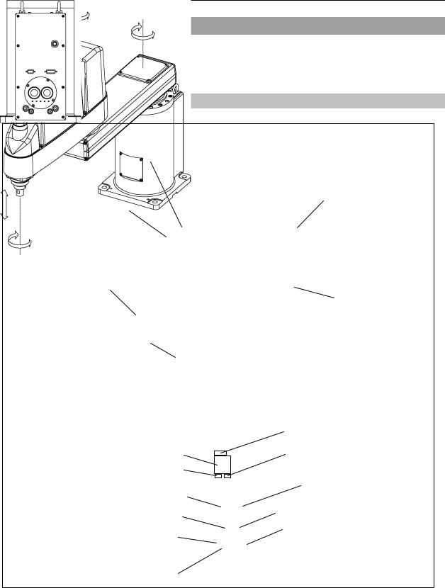
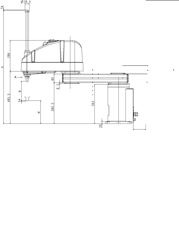
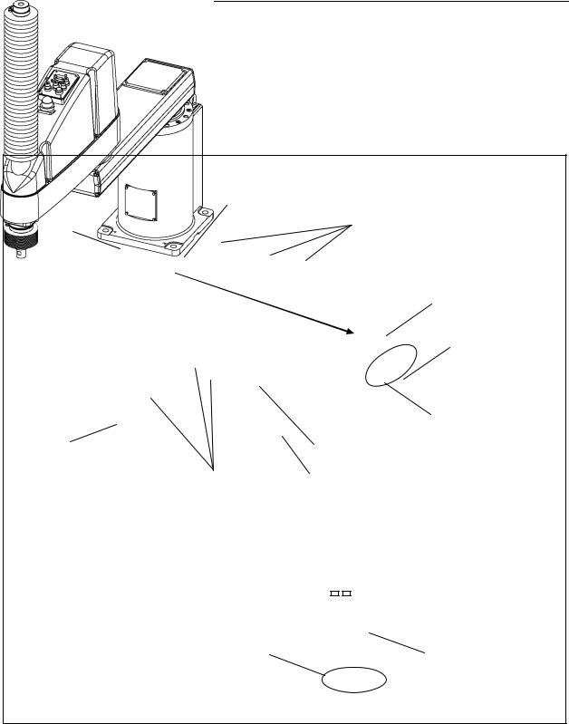
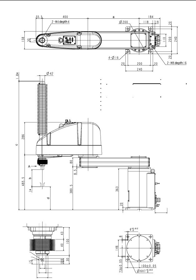
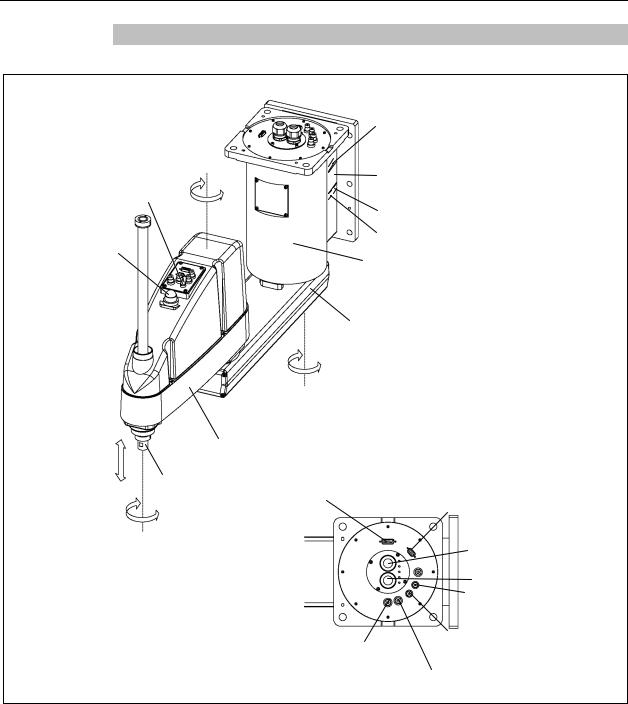
2.3.1Table Top Mounting
Standard-model : G10/G20-***S
|
Joint #2 |
|
Joint #3 and #4 |
(rotating) |
|
− |
||
brake release button |
||
+ |
||
|
||
LED lamp |
|
Arm #2
+
Joint #3 |
Shaft |
|
(up and down) |
||
|
||
|
−− |
|
|
+ |
|
|
Joint #4 |
|
|
(rotating) |
Signature label
(Serial No. of Manipulator) UR label
User connector
(9-pin D-sub connector)
Signal cable
Fitting (white)
for ø6 mm pneumatic tube
Fitting (white)
for ø4 mm pneumatic tube
Joint #1 (rotating)
−
+
Arm #1
Base
MT label
(only for custom specification) CE label
User connector
(15-pin D-sub connector)
Power cable
Fitting (black)
for ø6 mm pneumatic tube
 Fitting (black)
for ø4 mm pneumatic tube
NOTE |
- The brake release button affects both Joints #3 and #4. When the brake release button is pressed |
|
) |
||
in emergency mode, the brakes for both Joints #3 and #4 are released simultaneously. |
||
|
- When the LED lamp is lighting or the controller power is on, the current is being applied to the |
|
|
manipulator. Performing any work with the power ON is extremely hazardous and it may result |
|
|
in electric shock and/or improper function of the robot system. Make sure to turn OFF the |
|
|
controller power before the maintenance work. |
12 |
G10 / G20 Rev.10 |
Setup & Operation 2. Specifications
(Mount eyebolt at shipment)
|
G10-65*S |
|
G10/G20-85*S |
G20-A0*S |
|
a |
250 |
|
450 |
|
600 |
|
|
|
|
|
|
|
G10/G20-**1S |
|
G10/G20-**4S |
|
|
b |
180 |
420 |
|
|
|
c |
813.5 |
1053.5 |
|
|
|
d |
213.5 |
-26.5 |
|
|
|
(*) indicates the stroke margin by mechanical stop.
90 or more Space for cables
1 mm flat cut
Conical hole ø4,90° |
|
|||||
|
|
|
|
|
Max.ø18 through hole |
|
|
|
|
|
|
||
|
|
|
|
|
ø25 h7 shaft diameter |
Root both side chamfer C0.5 |
|
|
|
|
|||
|
|
|
|
|
ø39.5 mechanical stop diameter |
|
|
|
|
|
|
Reference through hole |
|
Detail of “A” |
||||||
(Calibration point position of Joints #3 and #4) |
(View from the bottom of the base) |
|||||
G10 / G20 Rev.10 |
13 |
Setup & Operation 2. Specifications
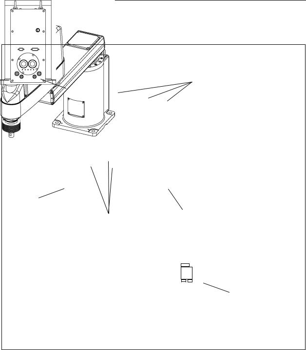
Cleanroom-model G10/G20-***C
The following figure shows the additional parts and specifications for the Table Top mounting Cleanroom-model when compared with the Standard-model in appearance.
Upper bellows
Plate cover
(For static electricity countermeasure)
Lower bellows
Cover
Plate cover for Table Top mounting surface (For static electricity
countermeasure)
Exhaust port
14 |
G10 / G20 Rev.10 |

Setup & Operation 2. Specifications
|
|
|
|
(Mount eyebolt |
|
|
|
|
|
at shipment) |
|
|
|
|
|
|
|
|
G10-65*C |
|
G10/G20-85*C |
G20-A0*C |
|
a |
250 |
450 |
600 |
|
|
|
|
|
|
|
|
|
G10/G20-**1C |
|
G10/G20-**4C |
|
|
b |
150 |
|
390 |
|
|
c |
870.5 |
1129.5 |
|
|
|
d |
205.5 |
-34.5 |
|
|
|
(*) indicates the stroke margin by mechanical stop. |
90 or more |
|
|
|
Space for cables |
1 mm flat cut
Conical hole ø4,90°
Max.ø18 through hole
ø25 h7 shaft diameter Root both side chamfer C0.5 ø39.5 mechanical stop diameter
Detail of “A” |
Reference through hole |
(Calibration point position of Joints #3 and #4) |
(View from the bottom of the base) |
G10 / G20 Rev.10 |
15 |
Setup & Operation 2. Specifications
Protected-model G10/G20-***D / P
The following figure shows the additional parts and specifications for the Table Top mounting Protected-model when compared with the Standard-model in appearance.
Normal G10/G20-***D* Manipulators do not have bellows. If necessary, select the bellows option at shipment. The following figure is a Manipulator with bellows option.
For dimensions of the end part of G10/G20-***D* without bellows option, refer to G10/G20-***S.
Upper bellows
Lower bellows
Stainless steel plate
G10/G20-***P only
Plate cover (For oil resistant)
|
|
|
|
|
|
User connector |
|
|
|
|
|
|
(Protected-model) |
|
|
|
|
|
|
Joint #3 and #4 |
|
|
|
|
|
|
brake release button |
|
|
|
|
|
|
(Protected-model) |
|
|
|
|
|
|
Fittings with cover |
|
|
|
|
|
|
(Protected-model) |
|
Stainless steel plate |
|||||
G10/G20-***P only |
Stainless steel plate |
|||||
Plate cover (For oil resistant) |
for Table Top mounting surface |
|||||
|
|
|
|
|
|
|
|
|
|
|
|
|
|
|
|
|
|
|
|
|
|
|
|
|
|
|
|
|
|
|
|
|
|
|
 Exhaust port
Fittings with cover
(Protected-model) User connector (Protected-model)
NOTE For Protected-model, all the screws used for outer parts are stainless steel screws. (Excluding the ) screw used for mechanical stop.)
16 |
G10 / G20 Rev.10 |
Setup & Operation 2. Specifications
(*) indicates the stroke margin by mechanical stop.
1 mm flat cut
Conical hole ø4,90°
Max.ø18 through hole ø25 h7 shaft diameter
ø39.5 mechanical stop diameter
Detail of “A”
(Calibration point position of Joints #3 and #4)
|
|
|
(Mount eyebolt |
|
|
|
|
at shipment) |
|
|
|
|
|
|
|
G10-65*P |
G10/G20-85*P |
G20-A0*P |
|
a |
250 |
450 |
600 |
|
|
|
|
|
|
|
G10/G20-**1P |
G10/G20-**4P |
|
|
b |
150 |
390 |
|
|
c |
874 |
1133 |
|
|
d |
205.5 |
-34.5 |
|
|
90 or more Space for cables
Root both side chamfer C0.5
Reference through hole (View from the bottom of the base)
G10 / G20 Rev.10 |
17 |
Setup & Operation 2. Specifications
2.3.2Wall Mounting
Standard-model G10/G20-***SW
|
|
|
|
|
|
MT label |
|
|
|
Joint #2 |
|
|
|
(only for custom specification) |
|
|
|
|
|
|
|
|
|
|
|
(rotating) |
|
|
|
Signature label |
|
Joint #3 and #4 |
− |
|
|
|
|||
|
|
|
|||||
+ |
|
|
|
(Serial No. of Manipulator) |
|||
|
|
|
|||||
brake release button |
|
|
|
||||
|
|
|
|
CE label |
|
||
|
|
|
|
|
|||
|
|
|
|
|
|
|
|
LED lamp |
|
|
|
|
|
UR label |
|
|
|
|
|
|
Base |
|
|
|
|
|
|
|
|
|
|
|
|
|
|
|
|
Arm #1 |
|
|
|
|
− |
|
|||
|
|
|
+ |
|
|||
|
|
|
Joint #1 |
|
|||
|
|
|
(rotating) |
|
|||
+ |
|
Arm #2 |
|
||||
Joint #3 |
|
|
|||||
(up and down) |
|
|
|
|
|
|
|
− |
− |
Shaft |
User connector |
User connector |
|||
|
(15-pin D-sub connector) |
||||||
|
|
+ |
|
|
|
|
(9-pin D-sub connector) |
|
|
|
|
|
|
|
|
Joint #4 |
|
|
|
|
|
Power cable |
|
(rotating) |
|
|
|
|
|||
|
|
|
|
|
|
|
Signal cable |
|
|
|
|
|
|
|
Fitting (black) |
|
|
|
|
|
|
|
for ø4 mm pneumatic tube |
|
|
|
Fitting (white) |
Fitting (white) |
|||
|
|
|
for ø6 mm pneumatic tube |
for ø4 mm pneumatic tube |
|||
Fitting (black)
for ø6 mm pneumatic tube
NOTE
)in emergency mode, the brakes for both Joints #3 and #4 are released simultaneously.
-When the LED lamp is lighting or the controller power is on, the current is being applied to the manipulator. Performing any work with the power ON is extremely hazardous and it may result in
electric shock and/or improper function of the robot system. Make sure to turn OFF the controller power before the maintenance work.- The brake release button affects both Joints #3 and #4. When the brake release button is pressed
18 |
G10 / G20 Rev.10 |
Loading...