


 Loading...
New Brunswick CO2 Incubator Shaker
S41i
Operating manual
M1334-0050
Revision B

Copyright
Copyright© 2013 Eppendorf AG, Germany. No part of this publication may be reproduced without the prior permission of the copyright owner.
The company reserves the right to change information in this document without notice. Updates to information in this document reflect our commitment to continuing product development and improvement.
Trademarks
Eppendorf® and the eppendorf logo are registered trademarks and New Brunswick and the New Brunswick logo are trademarks of Eppendorf AG, Germany.
BioCommand® is a registered trademark of New Brunswick Scientific Co., Inc., USA.
Windows® is a registered trademarks of Microsoft Corporation in the United States and other countries.
Microsoft® and Excel® are either registered trademarks or trademarks of Microsoft Corporation in the United States and/or other countries.
Trademarks are not marked in all cases with ™ or ® in this manual.
Eppendorf has attempted to identify the ownership of all trademarks from public records. Any omissions or errors are unintentional.
January 28, 2013
Revision B
M1334-0050

S41i CO2 Incubator Shaker — Operating manual
Table of contents
1 Operating instructions . . . . . . . . . . . . . . . . . . . . . . . . . . . . . . . . . . . . . . . . . . . . . . . . . . . . . . . . . . . . . . . . . . . . . . . 5
1.1 Using this manual . . . . . . . . . . . . . . . . . . . . . . . . . . . . . . . . . . . . . . . . . . . . . . . . . . . . . . . . . . . . . . . . . . . . . . . 5 1.2 Danger symbols and danger levels . . . . . . . . . . . . . . . . . . . . . . . . . . . . . . . . . . . . . . . . . . . . . . . . . . . . . . . . . 5 1.2.1 Hazard symbols . . . . . . . . . . . . . . . . . . . . . . . . . . . . . . . . . . . . . . . . . . . . . . . . . . . . . . . . . . . . . . . . . 5 1.2.2 Degrees of danger . . . . . . . . . . . . . . . . . . . . . . . . . . . . . . . . . . . . . . . . . . . . . . . . . . . . . . . . . . . . . . . 5
1.3 Symbols used . . . . . . . . . . . . . . . . . . . . . . . . . . . . . . . . . . . . . . . . . . . . . . . . . . . . . . . . . . . . . . . . . . . . . . . . . . 5 1.4 Abbreviations used . . . . . . . . . . . . . . . . . . . . . . . . . . . . . . . . . . . . . . . . . . . . . . . . . . . . . . . . . . . . . . . . . . . . . . 6
2 Product description . . . . . . . . . . . . . . . . . . . . . . . . . . . . . . . . . . . . . . . . . . . . . . . . . . . . . . . . . . . . . . . . . . . . . . . . . . 7
2.1 Main illustration. . . . . . . . . . . . . . . . . . . . . . . . . . . . . . . . . . . . . . . . . . . . . . . . . . . . . . . . . . . . . . . . . . . . . . . . . 7 2.2 Delivery package . . . . . . . . . . . . . . . . . . . . . . . . . . . . . . . . . . . . . . . . . . . . . . . . . . . . . . . . . . . . . . . . . . . . . . . 7 2.3 Features . . . . . . . . . . . . . . . . . . . . . . . . . . . . . . . . . . . . . . . . . . . . . . . . . . . . . . . . . . . . . . . . . . . . . . . . . . . . . . 8
3 Safety . . . . . . . . . . . . . . . . . . . . . . . . . . . . . . . . . . . . . . . . . . . . . . . . . . . . . . . . . . . . . . . . . . . . . . . . . . . . . . . . . . . . . 9
3.1 |
Intended use. . . . . . . . . . . . . . . . . . . . . . . . . . . . . . . . . . . . . . . . . . . . . . . . . . . . . . . . . . . . . . . . . . . . . . . . . . . |
9 |
3.2 |
Application limits. . . . . . . . . . . . . . . . . . . . . . . . . . . . . . . . . . . . . . . . . . . . . . . . . . . . . . . . . . . . . . . . . . . . . . . . |
9 |
|
3.2.1 Description of ATEX Guideline (94/9EC) . . . . . . . . . . . . . . . . . . . . . . . . . . . . . . . . . . . . . . . . . . . . . . |
9 |
3.3 |
Information on product liability . . . . . . . . . . . . . . . . . . . . . . . . . . . . . . . . . . . . . . . . . . . . . . . . . . . . . . . . . . . . . |
9 |
3.4 |
Warnings for intended use . . . . . . . . . . . . . . . . . . . . . . . . . . . . . . . . . . . . . . . . . . . . . . . . . . . . . . . . . . . . . . . |
10 |
|
3.4.1 Personal injury and damage to device . . . . . . . . . . . . . . . . . . . . . . . . . . . . . . . . . . . . . . . . . . . . . . . |
10 |
4 Installation . . . . . . . . . . . . . . . . . . . . . . . . . . . . . . . . . . . . . . . . . . . . . . . . . . . . . . . . . . . . . . . . . . . . . . . . . . . . . . . . 11
4.1 Inspection of boxes. . . . . . . . . . . . . . . . . . . . . . . . . . . . . . . . . . . . . . . . . . . . . . . . . . . . . . . . . . . . . . . . . . . . . 11 4.2 Unpacking. . . . . . . . . . . . . . . . . . . . . . . . . . . . . . . . . . . . . . . . . . . . . . . . . . . . . . . . . . . . . . . . . . . . . . . . . . . . 11 4.3 Utilities requirements . . . . . . . . . . . . . . . . . . . . . . . . . . . . . . . . . . . . . . . . . . . . . . . . . . . . . . . . . . . . . . . . . . . 11 4.4 Location . . . . . . . . . . . . . . . . . . . . . . . . . . . . . . . . . . . . . . . . . . . . . . . . . . . . . . . . . . . . . . . . . . . . . . . . . . . . . 12 4.5 Installation of foot shields . . . . . . . . . . . . . . . . . . . . . . . . . . . . . . . . . . . . . . . . . . . . . . . . . . . . . . . . . . . . . . . . 13 4.6 Platform assemblies . . . . . . . . . . . . . . . . . . . . . . . . . . . . . . . . . . . . . . . . . . . . . . . . . . . . . . . . . . . . . . . . . . . . 14 4.7 Installation of platform. . . . . . . . . . . . . . . . . . . . . . . . . . . . . . . . . . . . . . . . . . . . . . . . . . . . . . . . . . . . . . . . . . . 14 4.8 Flask clamp installation . . . . . . . . . . . . . . . . . . . . . . . . . . . . . . . . . . . . . . . . . . . . . . . . . . . . . . . . . . . . . . . . . 15 4.9 Stacking instructions. . . . . . . . . . . . . . . . . . . . . . . . . . . . . . . . . . . . . . . . . . . . . . . . . . . . . . . . . . . . . . . . . . . . 16 4.10 Electrical connections. . . . . . . . . . . . . . . . . . . . . . . . . . . . . . . . . . . . . . . . . . . . . . . . . . . . . . . . . . . . . . . . . . . 17 4.11 Setting up . . . . . . . . . . . . . . . . . . . . . . . . . . . . . . . . . . . . . . . . . . . . . . . . . . . . . . . . . . . . . . . . . . . . . . . . . . . . 17 4.12 Making connections . . . . . . . . . . . . . . . . . . . . . . . . . . . . . . . . . . . . . . . . . . . . . . . . . . . . . . . . . . . . . . . . . . . . 18 4.13 Ethernet connection . . . . . . . . . . . . . . . . . . . . . . . . . . . . . . . . . . . . . . . . . . . . . . . . . . . . . . . . . . . . . . . . . . . . 21
5 Operation . . . . . . . . . . . . . . . . . . . . . . . . . . . . . . . . . . . . . . . . . . . . . . . . . . . . . . . . . . . . . . . . . . . . . . . . . . . . . . . . . 22
5.1 Preparing for operation . . . . . . . . . . . . . . . . . . . . . . . . . . . . . . . . . . . . . . . . . . . . . . . . . . . . . . . . . . . . . . . . . . 22 5.2 Using the humidity trays . . . . . . . . . . . . . . . . . . . . . . . . . . . . . . . . . . . . . . . . . . . . . . . . . . . . . . . . . . . . . . . . . 22 5.3 Starting the incubator/shaker . . . . . . . . . . . . . . . . . . . . . . . . . . . . . . . . . . . . . . . . . . . . . . . . . . . . . . . . . . . . . 22 5.4 Using the touchscreen . . . . . . . . . . . . . . . . . . . . . . . . . . . . . . . . . . . . . . . . . . . . . . . . . . . . . . . . . . . . . . . . . . 23 5.4.1 Initial display and STATUS screen . . . . . . . . . . . . . . . . . . . . . . . . . . . . . . . . . . . . . . . . . . . . . . . . . . 23 5.4.2 Starting the platform . . . . . . . . . . . . . . . . . . . . . . . . . . . . . . . . . . . . . . . . . . . . . . . . . . . . . . . . . . . . . 24 5.4.3 Setting the temperature. . . . . . . . . . . . . . . . . . . . . . . . . . . . . . . . . . . . . . . . . . . . . . . . . . . . . . . . . . . 25
5.4.4 Setting the CO2 level. . . . . . . . . . . . . . . . . . . . . . . . . . . . . . . . . . . . . . . . . . . . . . . . . . . . . . . . . . . . . 26 5.4.5 Setting the shaking speed. . . . . . . . . . . . . . . . . . . . . . . . . . . . . . . . . . . . . . . . . . . . . . . . . . . . . . . . . 26
5.4.6 % RH. . . . . . . . . . . . . . . . . . . . . . . . . . . . . . . . . . . . . . . . . . . . . . . . . . . . . . . . . . . . . . . . . . . . . . . . . 27 5.5 MENU 1 screen . . . . . . . . . . . . . . . . . . . . . . . . . . . . . . . . . . . . . . . . . . . . . . . . . . . . . . . . . . . . . . . . . . . . . . . 28 5.5.1 HELP function . . . . . . . . . . . . . . . . . . . . . . . . . . . . . . . . . . . . . . . . . . . . . . . . . . . . . . . . . . . . . . . . . . 28 5.5.2 EVENT LOG . . . . . . . . . . . . . . . . . . . . . . . . . . . . . . . . . . . . . . . . . . . . . . . . . . . . . . . . . . . . . . . . . . . 28 5.5.3 ALARM SETTINGS screen. . . . . . . . . . . . . . . . . . . . . . . . . . . . . . . . . . . . . . . . . . . . . . . . . . . . . . . . 30 5.5.4 SUMMARY screen . . . . . . . . . . . . . . . . . . . . . . . . . . . . . . . . . . . . . . . . . . . . . . . . . . . . . . . . . . . . . . 32
1
contents of Table
3

1
Table of contents
S41i CO2 Incubator Shaker — Operating manual
5.5.5 EVENT GRAPH screen . . . . . . . . . . . . . . . . . . . . . . . . . . . . . . . . . . . . . . . . . . . . . . . . . . . . . . . . . . 33 5.5.6 SET CALIBRATION screen. . . . . . . . . . . . . . . . . . . . . . . . . . . . . . . . . . . . . . . . . . . . . . . . . . . . . . . . 36 5.5.7 GENERAL SETTINGS screen . . . . . . . . . . . . . . . . . . . . . . . . . . . . . . . . . . . . . . . . . . . . . . . . . . . . . 38 5.5.8 USER ACCESS screen. . . . . . . . . . . . . . . . . . . . . . . . . . . . . . . . . . . . . . . . . . . . . . . . . . . . . . . . . . . 43 5.5.9 COMMUNICATIONS screen . . . . . . . . . . . . . . . . . . . . . . . . . . . . . . . . . . . . . . . . . . . . . . . . . . . . . . . 47
5.6 MENU 2 screen . . . . . . . . . . . . . . . . . . . . . . . . . . . . . . . . . . . . . . . . . . . . . . . . . . . . . . . . . . . . . . . . . . . . . . . 48 5.6.1 SERVICE screen. . . . . . . . . . . . . . . . . . . . . . . . . . . . . . . . . . . . . . . . . . . . . . . . . . . . . . . . . . . . . . . . 48 5.6.2 DIAGNOSTICS screen . . . . . . . . . . . . . . . . . . . . . . . . . . . . . . . . . . . . . . . . . . . . . . . . . . . . . . . . . . . 48 5.6.3 MAINTENANCE screen . . . . . . . . . . . . . . . . . . . . . . . . . . . . . . . . . . . . . . . . . . . . . . . . . . . . . . . . . . 49 5.6.4 OPTIONS screen . . . . . . . . . . . . . . . . . . . . . . . . . . . . . . . . . . . . . . . . . . . . . . . . . . . . . . . . . . . . . . . 54
5.6.5 SET CO2 AUTOZERO screen. . . . . . . . . . . . . . . . . . . . . . . . . . . . . . . . . . . . . . . . . . . . . . . . . . . . . . 55 5.6.6 DISINFECTION screen. . . . . . . . . . . . . . . . . . . . . . . . . . . . . . . . . . . . . . . . . . . . . . . . . . . . . . . . . . . 59
5.7 Mains/Power interruption . . . . . . . . . . . . . . . . . . . . . . . . . . . . . . . . . . . . . . . . . . . . . . . . . . . . . . . . . . . . . . . . 61
6 Maintenance . . . . . . . . . . . . . . . . . . . . . . . . . . . . . . . . . . . . . . . . . . . . . . . . . . . . . . . . . . . . . . . . . . . . . . . . . . . . . . . 62
6.1 |
Routine maintenance . . . . . . . . . . . . . . . . . . . . . . . . . . . . . . . . . . . . . . . . . . . . . . . . . . . . . . . . . . . . . . . . . . . |
62 |
|
|
6.1.1 |
General notes . . . . . . . . . . . . . . . . . . . . . . . . . . . . . . . . . . . . . . . . . . . . . . . . . . . . . . . . . . . . . . . . . . |
62 |
|
6.1.2 |
Daily checks . . . . . . . . . . . . . . . . . . . . . . . . . . . . . . . . . . . . . . . . . . . . . . . . . . . . . . . . . . . . . . . . . . . |
62 |
|
6.1.3 |
Weekly checks . . . . . . . . . . . . . . . . . . . . . . . . . . . . . . . . . . . . . . . . . . . . . . . . . . . . . . . . . . . . . . . . . |
62 |
|
6.1.4 |
Monthly check . . . . . . . . . . . . . . . . . . . . . . . . . . . . . . . . . . . . . . . . . . . . . . . . . . . . . . . . . . . . . . . . . . |
62 |
|
6.1.5 |
Other checks. . . . . . . . . . . . . . . . . . . . . . . . . . . . . . . . . . . . . . . . . . . . . . . . . . . . . . . . . . . . . . . . . . . |
62 |
|
6.1.6 CO2 Sampling with Analyzer. . . . . . . . . . . . . . . . . . . . . . . . . . . . . . . . . . . . . . . . . . . . . . . . . . . . . . . |
62 |
|
6.2 |
Cleaning . . . . . . . . . . . . . . . . . . . . . . . . . . . . . . . . . . . . . . . . . . . . . . . . . . . . . . . . . . . . . . . . . . . . . . . . . . . . . |
63 |
|
6.3 |
Disinfection/Decontamination . . . . . . . . . . . . . . . . . . . . . . . . . . . . . . . . . . . . . . . . . . . . . . . . . . . . . . . . . . . . . |
63 |
|
6.4 |
Product return . . . . . . . . . . . . . . . . . . . . . . . . . . . . . . . . . . . . . . . . . . . . . . . . . . . . . . . . . . . . . . . . . . . . . . . . . |
64 |
|
7 Transport, storage and disposal . . . . . . . . . . . . . . . . . . . . . . . . . . . . . . . . . . . . . . . . . . . . . . . . . . . . . . . . . . . . . . 65
7.1 Disposal . . . . . . . . . . . . . . . . . . . . . . . . . . . . . . . . . . . . . . . . . . . . . . . . . . . . . . . . . . . . . . . . . . . . . . . . . . . . . 65
8 Technical data . . . . . . . . . . . . . . . . . . . . . . . . . . . . . . . . . . . . . . . . . . . . . . . . . . . . . . . . . . . . . . . . . . . . . . . . . . . . . 66
8.1 |
Weight/dimensions . . . . . . . . . . . . . . . . . . . . . . . . . . . . . . . . . . . . . . . . . . . . . . . . . . . . . . . . . . . . . . . . . . . . . |
66 |
|
|
8.1.1 |
Device dimensions . . . . . . . . . . . . . . . . . . . . . . . . . . . . . . . . . . . . . . . . . . . . . . . . . . . . . . . . . . . . . . |
66 |
|
8.1.2 |
Platform dimensions . . . . . . . . . . . . . . . . . . . . . . . . . . . . . . . . . . . . . . . . . . . . . . . . . . . . . . . . . . . . . |
66 |
8.2 |
Application parameters . . . . . . . . . . . . . . . . . . . . . . . . . . . . . . . . . . . . . . . . . . . . . . . . . . . . . . . . . . . . . . . . . . |
66 |
|
|
8.2.1 |
Speed . . . . . . . . . . . . . . . . . . . . . . . . . . . . . . . . . . . . . . . . . . . . . . . . . . . . . . . . . . . . . . . . . . . . . . . . |
66 |
|
8.2.2 |
CO2 Management . . . . . . . . . . . . . . . . . . . . . . . . . . . . . . . . . . . . . . . . . . . . . . . . . . . . . . . . . . . . . . . |
66 |
|
8.2.3 |
Temperature . . . . . . . . . . . . . . . . . . . . . . . . . . . . . . . . . . . . . . . . . . . . . . . . . . . . . . . . . . . . . . . . . . . |
66 |
|
8.2.4 |
Passive humidity . . . . . . . . . . . . . . . . . . . . . . . . . . . . . . . . . . . . . . . . . . . . . . . . . . . . . . . . . . . . . . . . |
67 |
8.3 |
Power supply . . . . . . . . . . . . . . . . . . . . . . . . . . . . . . . . . . . . . . . . . . . . . . . . . . . . . . . . . . . . . . . . . . . . . . . . . |
67 |
|
9 Ordering information . . . . . . . . . . . . . . . . . . . . . . . . . . . . . . . . . . . . . . . . . . . . . . . . . . . . . . . . . . . . . . . . . . . . . . . . 68
9.1 Accessories . . . . . . . . . . . . . . . . . . . . . . . . . . . . . . . . . . . . . . . . . . . . . . . . . . . . . . . . . . . . . . . . . . . . . . . . . . 68
10 Declaration of conformity . . . . . . . . . . . . . . . . . . . . . . . . . . . . . . . . . . . . . . . . . . . . . . . . . . . . . . . . . . . . . . . . . . . . 69
Index . . . . . . . . . . . . . . . . . . . . . . . . . . . . . . . . . . . . . . . . . . . . . . . . . . . . . . . . . . . . . . . . . . . . . . . . . . . . . . . . . . . . . 70
4

S41i CO2 Incubator Shaker — Operating manual
1Operating instructions
1.1Using this manual
Carefully read this operating manual before using the device for the first time.
Also observe the operating manual enclosed with the accessories.
The operating manual should be considered as part of the product and stored in a location that is easily accessible.
When passing the device on to third parties, be sure to include this operating manual.
If this manual is lost, please request another one. The current version can be found on our website http://newbrunswick.eppendorf.com.
1.2Danger symbols and danger levels
1.2.1 Hazard symbols
Hazard point |
Burns |
Electric shock |
Material damage |
Explosion |
Heavy loads |
Inhalation |
Crush |
1.2.2Degrees of danger
The following degree levels are used in safety messages throughout this manual. Acquaint yourself with each item and the potential risk if you disregard the safety message.
DANGER |
Will lead to severe injuries or death. |
|
|
WARNING |
May lead to severe injuries or death. |
|
|
CAUTION |
May lead to light to moderate injuries. |
|
|
NOTICE |
May lead to material damage. |
|
|
1.3Symbols used
Example Meaning
You are requested to perform an action.
1.Perform these actions in the sequence described.
•List.
References useful information.
1
instructions Operating
5

1
Operating instructions
S41i CO2 Incubator Shaker — Operating manual
1.4Abbreviations used
kWh Kilowatt hours
LEL Lower Explosion Limit rpm Revolutions Per Minute UEL Upper Explosion Limit
VA Volt Amps
VAC Voltage in Alternating Current
6
S41i CO2 Incubator Shaker — Operating manual
2Product description
2.1Main illustration
2
description Product
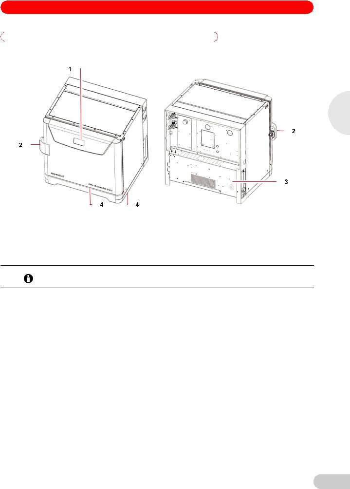
Fig. 1: |
Front and rear views |
|
|
|
|
|
|
|
|
1 |
Display |
3 |
Control box |
|
|
|
|
|
|
2 |
Door handle |
4 |
Foot shield |
|
|
|
|
|
|
2.2Delivery package
The operating manual and mains/power cord are shipped on top of the control box at the rear of the incubator/shaker.
Quantity |
Item |
Notes |
|
|
|
|
|
1 |
Perforated Stainless Steel Shelf |
Installed |
|
|
|
|
|
1 |
White porous CO2 Sensor Cover |
|
|
1 |
Black Sensor Cover |
|
|
|
|
|
|
1 |
Front foot shield |
Packed on top of incubator/ |
|
|
|
shaker |
|
2 |
Side foot shields |
||
|
|||
|
|
|
|
2 |
Humidity Trays |
Packed in box on shelf |
|
|
|
|
|
3 m (9.8 ft) |
PVC Tubing, ~6 mm (1/4 in) bore, with an |
Packed in box on shelf |
|
|
inline CO2 HEPA-filter connected, ready for |
|
|
|
use |
|
|
|
|
|
|
2 |
Hose Clips |
Packed in humidity tray |
|
|
|
|
|
1 |
Auto-zero HEPA Filter |
|
|
|
|
|
|
1 |
Mains/power Cord |
Packed on top of control box at |
|
|
|
rear of incubator/shaker |
|
1 |
Operating Manual |
||
|
|||
|
|
|
7

2
Product description
S41i CO2 Incubator Shaker — Operating manual
|
|
Risk of silica particulates transferring to skin |
|
|
Wear gloves anytime you touch the white CO2 sensor cover. |
|
CAUTION! |
Do not later touch those gloves to your face. |
|
Discard or wash the gloves. |
|
|
|
|
|
|
|
2.3 |
Features |
|
The chamber’s fanless design with six-sided convection heating provides gentle circulation and uniform temperature. In addition, the seamless one-piece chamber eliminates area where contaminants could collect and makes wipe-down easy.
Two humidity trays reduce sample evaporation.
The New Brunswick S41i fits on the floor, on the floor under a work bench or it can be double stacked to save space. The shaking mechanism is a heavy-duty drive with three eccentric drive shafts to provide stability, uniform motion and assure long incubator/shaker life. The orbit is 2.5 cm (1 in) and the shaking speed range is from 25 - 400 rpm (± 1 rpm), unless two are stacked, in which case the maximum speed of the top incubator/shaker is limited to 250 rpm.
With no shelf present, flasks up to 4 L in size can be installed on the shaking platform. With one stationary shelf present, Erlenmeyer flasks up to 1 L can be installed. If two shelves are present, Erlenmeyer flasks, because of their tall necks, must be limited to 250 mL.
The temperature range is from 4 °C above ambient temperature to 50 °C. Temperature accuracy is ± 0.2 °C through the entire range.
CO2 control ranges from 0.2 to 20 %, with an accuracy of ± 0.1 % at 20 % CO2 via the InfraRed CO2 sensor.
8
S41i CO2 Incubator Shaker — Operating manual
3Safety
3.1Intended use
The New Brunswick S41i is half CO2 incubator and half biological shaker, combining the best features of New Brunswick incubators and shakers into one versatile instrument. It provides gentle shaking and accurate control of temperature, CO2 gas concentrations, enabling growth of hybridomas, mammalian and stem cells, insect cultures, as well as aerobic and anaerobic bacteria and yeast. A perforated stationary shelf is included for plates and T-flasks to enable simultaneous incubation of adherent cultures.
The New Brunswick S41i was designed for controlled incubation and shaking of biological samples. Do not use any heat-generating device inside the chamber.
|
Lack of safety due to incorrect accessories or spare parts |
|
Accessories and spare parts that are not recommended by Eppendorf compromise the safety, |
CAUTION! |
function and precision of the device. Eppendorf cannot be held liable or accept any liability for |
damage resulting from the use of non-recommended accessories and spare parts. |
Only use accessories and original spare parts recommended by Eppendorf.
When one shelf is installed, the largest flasks that can be contained in this incubator/shaker are 1 L Erlenmeyer and 2.8 L Fernbach flasks. Without a shelf, Erlenmeyer flasks up to 4 L can be contained.
3.2Application limits
3.2.1Description of ATEX Guideline (94/9EC)
Explosion hazard
Do not operate the device in areas where work is completed with explosive substances.
DANGER! |
Do not use this device to process any explosive or highly reactive substances. |
|
Do not use this device to process any substances which could create an explosive |
||
|
||
|
atmosphere. |
Due to its design and the ambient conditions in its interior, the device is not suitable for use in potentially explosive atmospheres.
The device may only be used in a safe environment, e.g., the open atmosphere of a ventilated lab.
The use of substances which may contribute to a potentially explosive atmosphere is not permitted.
The final decision regarding the risks associated with using these types of substances is the user's responsibility.
3.3Information on product liability
In the following cases, the designated protection of the device may be compromised.
The liability for the function of the device passes to the operator if:
•The device is not used in accordance with this operating manual.
•The device is used outside of the range of application described in the succeding chapters.
•The device is used with accessories or consumables that were not approved by Eppendorf.
•Service or maintenance is completed on the device by people who are not authorized by Eppendorf.
•The owner has made unauthorized modifications to the device.
3
Safety
9
3
Safety
S41i CO2 Incubator Shaker — Operating manual
3.4Warnings for intended use
Before using the incubator/shaker, read the operating manual and observe the following general safety instructions.
3.4.1Personal injury and damage to device
|
Risk of personal injury |
|
|
Burns due to hot surface. |
|
WARNING! |
Do not touch the incubator/shaker during the high temperature disinfection cycle. |
|
Do not open incubator/shaker door during the cycle. |
||
|
Risk of personal injury
A mechanical lifting device is required to safely lift the incubator/shaker.
CAUTION!
Risk of material damage
Never try to lift the incubator/shaker by its door; this would cause permanent damage to the
NOTICE!
incubator/shaker.
Never lean on or place objects on the open door.
Risk of material damage
To avoid possible damage to the CO2 sensor, never leave water in the humidity trays while the
NOTICE!
incubator/shaker is switched off, or when a high temperature disinfection cycle is initiated.
Allow a clearance of 50 mm (2 in) to allow access for oxygen sensor removal (optional feature).
10
S41i CO2 Incubator Shaker — Operating manual
4Installation
4.1Inspection of boxes
After you have received your order, inspect the boxes carefully for any damage that may have occurred during shipping. Report any damage to the carrier and to your local Eppendorf distributor immediately.
4.2Unpacking
Risk of personal injury
A mechanical lifting device is required to safely lift the incubator/shaker.
CAUTION!
Risk of material damage
Never try to lift the incubator/shaker by its door; this would cause permanent damage to the
NOTICE!
incubator/shaker.
Never lean on or place objects on the open door.
Save the packing materials for possible future use, and be sure to save this Operating Manual for instruction and reference. User manuals can also be found online, in PDF format, at www.nbsc.com.
Save the foot shields packed on top of the incubator/shaker, which you will install.
Use a mechanical lifting device to safely lift the incubator/shaker off its shipping pallet and to transport it to the installation site (see Location on p. 12). You may push the incubator/shaker a short distance using the built-in castors to roll it. To do this, you may need to rotate the incubator/shaker feet to raise them so the incubator/shaker will rest on its castors.
Remove the sleeved box sitting on the top shelf inside the incubator/shaker. As indicated in Delivery package (see Delivery package on p. 7), It contains the two humidity trays, PVC tubing and several other essential parts.
Remove the foam blocks from the top shelf and save them with the other packing materials.
Locate and remove the parts stored in the humidity trays.
Locate and unpack any other components.
If any part of your order was damaged during shipping, is missing, or fails to operate, please contact your Eppendorf distributor.
Using your packing list, verify that you have received the correct materials, and that nothing is missing.
4.3Utilities requirements
|
|
The following utilities requirements are needed for operation: |
|
|
|
|
|
Utility |
|
Requirement |
|
|
|
|
|
Electricity |
|
120 V, 50/60 Hz earthed/grounded mains/electrical supply |
|
|
|
|
|
|
|
|
230 V, 50/60 Hz earthed/grounded mains/electrical supply |
|
|
|
|
CO2 gas |
|
Cylinder with 100 % CO2 vapor withdrawal |
|
|
|
|
|
|
|
CO2 gas pressure to device must exceed 7 PSI (0.5 bar) for optimal operation. |
|
|
|
||
|
|
|
|
|
|
|
|
4
Installation
11
S41i CO2 Incubator Shaker — Operating manual
4.4Location
The incubator/shaker is designed to operate at a chamber temperature of 4.0 °C above ambient. If the incubator/shaker is being operated at 37 °C, the absolute minimum ambient temperature recommended is 18 °C. Maximum allowable ambient temperature is 25 °C.
Position the incubator/shaker, allowing enough space to open the door and to access the CO2 sample port on the right side of the incubator/shaker.
Care should be taken to avoid placing the incubator/shaker in a position that may affect its performance, such as those listed below.
DO NOT place the incubator/shaker:
•Directly under, beside or within the air flow of heating or air-conditioning ducts, or other drafts
•Directly beside heat-generating equipment such as a heater, an autoclave or an oven
•Near the exhaust of heator cold-generating equipment (like an ultra-low temperature freezer)
•Near a window exposed to direct sunlight
•Directly on top of any heat-generating apparatus
•Without minimum ventilation clearance of 10 mm (0.5 in) all around
4 |
|
Risk of material damage |
|
|
|
|
|
Never try to lift the incubator/shaker by its door; this would cause permanent damage to the |
|
NOTICE! |
incubator/shaker. |
|
Never lean on or place objects on the open door. |
|
|
|
|
|
|
|
Installation |
|
Remove the incubator/shaker from the pallet as described in Unpacking (see Unpacking on |
|
p. 11). |
|
|
|
|
|
|
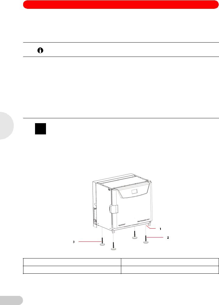
Place the incubator/shaker in the working position, on a level floor capable of bearing its |
|
|
weight. You may need to rotate the incubator/shaker feet to raise them, in order to rest the |
|
|
incubator/shaker on its castors to be moved more easily (see Fig. 2 on p. 12). |
Fig. 2: Adjustable feet
1 Castors located in all four corners |
3 Lock nut |
2 Adjustable foot
12

S41i CO2 Incubator Shaker — Operating manual
The weight of the incubator/shaker is approximately 152 kg (335 lb), but actual in-use weight will naturally be heavier and will depend on both the options installed and the material stored in the incubator/shaker.
The incubator/shaker is designed so that one incubator/shaker can be safely stacked on top of another S41i using the optional stacking kit, which includes instructions. It is not possible to put any other type of incubator/shaker or heavy apparatus on top, as the top cover and stacking kit are designed to support only the feet of another S41i.
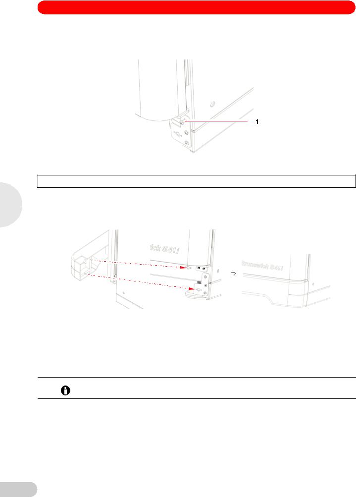
4.5Installation of foot shields
The front and side foot shields (see Fig. 3 on p. 13) are packed on top of the incubator/shaker, enclosed in bubble wrap. To install them, beginning with the right side foot shield, follow this procedure:
1.Orient the mounting bracket at the front face of the incubator/shaker, then align the foot shield’s two keyhole slots with the two mounting pins on the bottom of the incubator/shaker.
4
Installation
Fig. 3: Front and side foot shields
Fig. 4: |
Side foot shield installation |
|
|
|
|
|
|
|
|
1 |
Right side of incubator/shaker |
4 |
Hole for front foot shield’s ball catch |
|
|
|
|
|
|
2 |
Keyhole slot on right side foot shield |
5 |
Hole for M4 screw |
|
|
|
|
|
|
3 |
Mounting bracket |
|
|
|
|
|
|
|
|
13
S41i CO2 Incubator Shaker — Operating manual
2.Snap the side shield in place, then slide it toward the back of the incubator/shaker until the bracket is flush against the front face.
3.Fasten the bracket to the incubator/shaker with one M4 screw:
4
Installation
Fig. 5: Side foot shield bracket
1M4 screw inserted here to fasten the side foot shield bracket to the incubator/shaker
4.Repeat Steps 1 through 3 for the left side foot shield.
5.Push fit the remaining foot shield onto the bottom front of the incubator/shaker. Be sure to align its pins with the holes on the incubator/shaker and on the mounting brackets of the side foot shields.
Fig. 6: Front foot shield installation
4.6Platform assemblies
A platform, which is required for operation, is a separate item, not included with the shaker assembly. The S41i platform, measuring 612 × 356 mm (24 × 14 in), will accept a wide range of clamps for flasks, test tubes, etc.
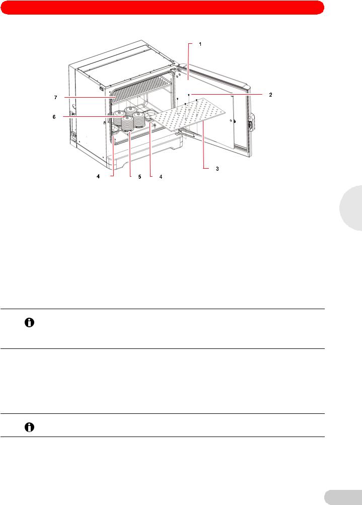
4.7Installation of platform
Prior to use, a platform must be installed on the incubator/shaker.
The incubator/shaker is shipped with four Allen head platform screws installed in the four bearing housing uprights, as shown below:
14
S41i CO2 Incubator Shaker — Operating manual
Fig. 7: |
Installing platform |
|
|
|
|
|
|
|
|
1 |
Glass inner door |
5 |
Bearing housing |
|
|
|
|
|
|
2 |
Allen screws |
6 |
Bearing housing uprights |
|
|
|
|
|
|
3 |
Platform |
7 |
Top shelf, shipped installed |
|
|
|
|
|
|
4 |
Humidity trays |
|
|
|
|
|
|
|
|
1.Set the mains/power to OFF and unplug the incubator/shaker.
2.Remove the platform screws, then use them to install the platform over the bearing housing.
4.8Flask clamp installation
Flask clamps purchased for use with the platform require installation. Clamps are installed by securing the base of the clamp to the platform with the correct type and number of screws. All clamps are shipped complete with hardware.
The S41i platform requires 10-24 × 5/16-inch Phillips-head screws (which are supplied) to fasten flask clamps.
With one shelf installed, Erlenmeyer flasks larger than 1 L are too tall for the chamber; to use 2 L – 4 L Erlenmeyer flasks, remove the shelf.
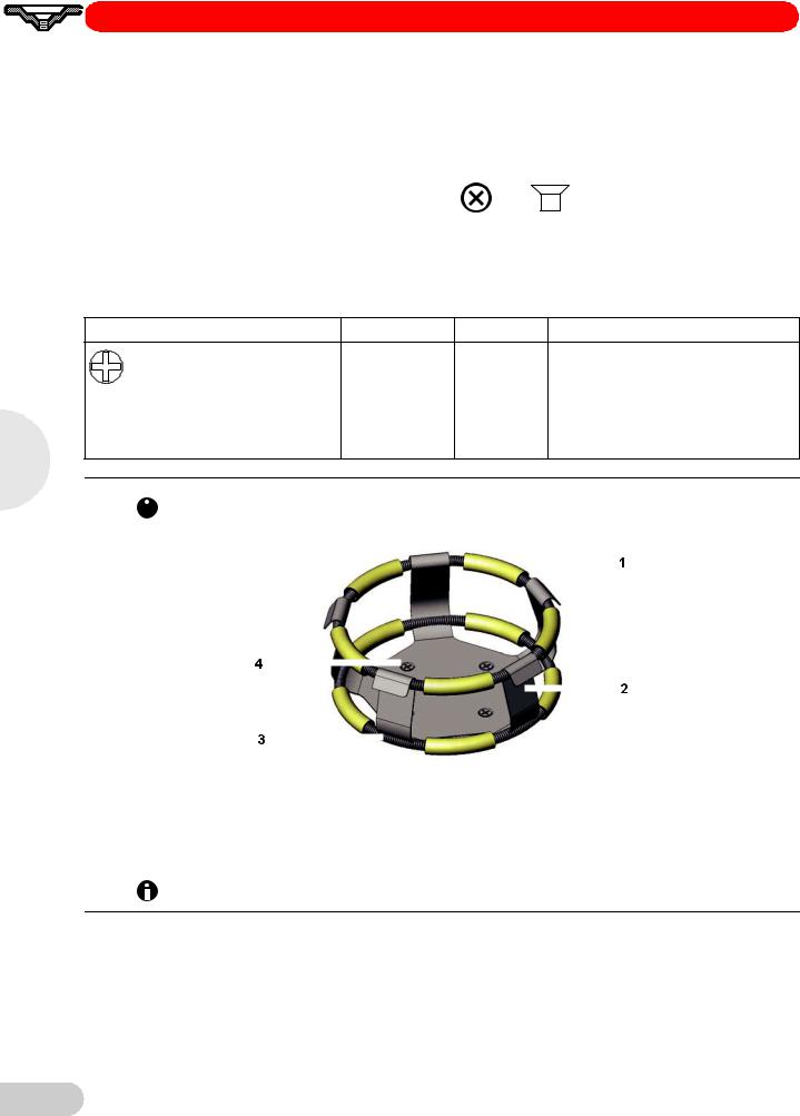
Clamps for 2.8-liter Fernbach flasks and 2 L – 4 L Erlenmeyer flasks are shipped with an additional girdle to keep the flasks in place. The girdle is an assembly of springs and sections of rubber tubing. One girdle is already in place on the clamp, the other is packed separately.
To install these double girdle clamps:
1.Place the clamp on the platform, aligning its mounting holes with holes on the platform. Secure the clamp in place using the flat Phillips head screws provided
(#S2116-3051, 10-24 x 5/16-inch).
Three different types of screws are shipped with the clamps, to identify the proper screws (see Fig. 8 on p. 16).
2.With the first girdle in place, as delivered, on the upper part of the clamp body, insert an empty flask into the clamp.
4
Installation
15
4
Installation
S41i CO2 Incubator Shaker — Operating manual
3.After making sure the sections of tubing are located between the clamp legs, roll the first girdle down the legs of the clamp as far as it can go. The tubing sections will rest against the platform, and the springs will be under the clamp base.
4.Place the second girdle around the upper portion of clamp body (just as the first girdle was initially). Make sure that its spring sections rest against the clamp legs, while its rubber tubing sections sit against the flask, in between the clamp legs.
Fig. 8: Clamp fastener
New Brunswick flask clamps are used on a variety of incubator/shaker platforms. Flat head screws of different lengths and thread pitch are used to secure the clamp. The following table identifies the proper screw for your incubator/shaker application by reference to the head style. Select the appropriate screws and set the others aside.
Description |
Part number |
Qty |
Application |
|
S2116-3051 |
1 |
5/16" (7.9 mm) thick aluminum, phenolic |
10-24 × 5/16 (7.9 mm) flat Phillips |
|
|
and stainless steel platforms. |
|
|
|
|
(+) head screw |
|
|
|
One-liter and larger flask clamps are fastened with 5 screws.
|
|
|
|
|
|
|
|
|
|
|
|
|
|
|
|
|
|
|
|
|
|
Abb. 9: |
Double girdle clamp installation |
|||||||||
|
|
|
|
|
|
|
|
|
|
|
|
|
|
|
|
|
|
|
|
|
|
|
|
|
|
|
|
|
|
|
|
|
|
|
|
|
|
|
|
|
|
|
|
Fig. 9: |
Double girdle clamp installation |
|
|
|
|
|
|
|
|
1 |
Upper girdle with girdle tubes |
3 |
Lower girdle with girdle tubes |
|
|
|
|
|
|
2 |
Clamp body (legs and base) |
4 |
Clamp mounting holes (quantity: 5) |
|
|
|
|
|
|
|
|
|
|
|
The upper girdle secures the flask within the clamp, and the bottom girdle keeps the flask from spinning.
4.9Stacking instructions
To stack two S41i incubator shakers, you must first have purchased the stacking kit. You will find the instructions contained in the kit.
16

S41i CO2 Incubator Shaker — Operating manual
4.10Electrical connections
Risk of electrical hazard
Before making electrical connections, be sure to check the following list.
CAUTION!
1.If you have not already done so, check that the voltage and frequency of your incubator/ shaker are compatible with your mains/electric supply.
2.Set the circuit breaker on the left side of the incubator/shaker to the OFF position.
ONLY THEN:
Risk of material damage
An earthed/grounded electrical outlet is necessary for the safe operation of this instrument.
NOTICE!
3. Plug the mains/power cord into an earthed/grounded electrical outlet.
4.11Setting up
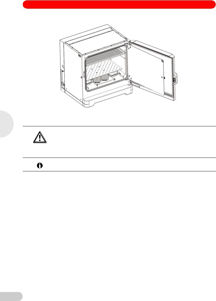
1.If necessary, level the incubator/shaker by adjusting the feet, after removing the foot shields. Place a small level on the shelf of the incubator/shaker. Adjust the leveling feet until the incubator/shaker is level and stable. Lock the leveling feet in place by tightening the locking nuts on each foot. Reinstall the foot shields.
2.Fill each humidity tray halfway with water (approximately 250 mL) if you wish to use them for humidification.
Be sure to install the humidity trays one at a time, after wiping the bottom and edges dry.
If you will not use them for humidification, install them anyway to catch spills.
3.Place the humidity trays one at a time onto the parallel support rods on either side of the bearing housing at the bottom of the incubator/shaker. Sit them behind the stopper bends, making sure that the back edge of each tray fits under the end of the condensation/spill channel.
4
Installation
Fig. 10: Installing the humidity trays
17
S41i CO2 Incubator Shaker — Operating manual
4
Installation
Fig. 11: Humidity trays, installed
4.12Making connections
|
Risk of explosion |
|
|
Use gases in this equipment only within the range between their lower explosion limit (LEL) |
|
WARNING! |
and their upper explosion limit (UEL). |
|
If your process requires or produces gases, be sure to verify their LEL and UEL concentration |
||
|
||
|
range (available online or ask your gas supplier). |
In-line regulators are provided on the back of the incubator/shaker. These are essential to proper operation.
1.Connect the incubator/shaker to the CO2 supply using the ~ 6 mm plastic tubing (with installed HEPA filter) by attaching the tubing from the supply to the top regulator inlet on the
back of the incubator/shaker. The bottom regulator inlet is reserved for N2 if your incubator/ shaker is equipped with the oxygen control option.
18
S41i CO2 Incubator Shaker — Operating manual
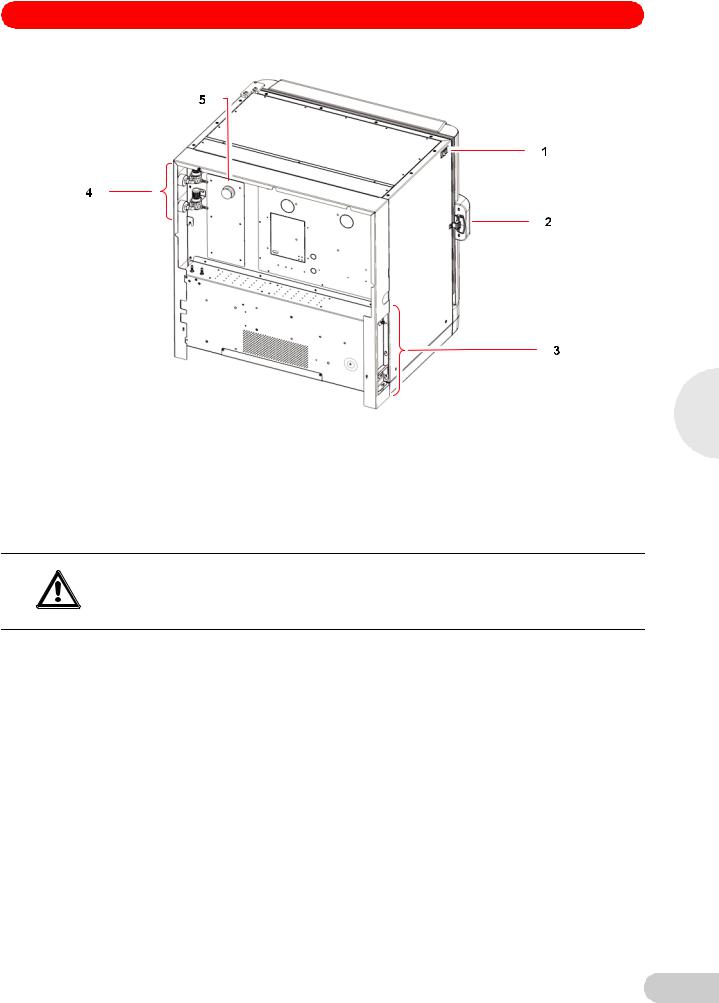
Fig. 12: Rear view (back panel removed)
1 |
ON/OFF switch |
4 |
Inline gas regulators (access from the side) |
|
|
|
|
2 |
Door handle |
5 |
Access port |
|
|
|
|
3 |
See Control box (right side) figure for details. |
|
|
|
|
|
|
2. Use the tubing clips provided to eliminate CO2 leaks.
Risk of electrical hazard
Before making electrical connections, verify that your mains/power supply voltage matches
the voltage of your incubator/shaker and that the on/off switch is in the OFF position.
WARNING!
3.Plug the mains/power cord into its receptacle on the right side of the control box.
4.After verifying that your supply voltage matches the voltage specified for your incubator/ shaker and that the ON/OFF switch is OFF, plug the cord into your mains/power supply outlet.
5.Press the Auto-Zero HEPA filter gently into the white plastic filter socket on the right side of the control box.
4
Installation
19

S41i CO2 Incubator Shaker — Operating manual
4
Installation
Fig. 13: Control box (right side)
1 |
Door handle |
4 |
Auto Zero filter socket |
||||
|
|
|
|
|
|
|
|
2 |
Adjustable foot (shown with side shield) |
5 |
Back panel in place |
||||
|
|
|
|
|
|
|
|
3 |
Mains/power receptacle |
|
|
|
|
|
|
|
|
|
|
|
|
|
|
|
|
|
|
|
|
|
|
|
|
|
|
|
|
|
|
|
|
|
|
|
|
|
|
Fig. 14: Control box (left side)
1 |
(Shown with back panel removed) |
3 Adjustable foot (shown without side shield) |
|
|
|
2 |
Ethernet connection |
|
|
|
|
20
S41i CO2 Incubator Shaker — Operating manual
4.13Ethernet connection
The ethernet connection is provided as a connection to a personal computer on which you can run New Brunswick BioCommand® SFI software to control the incubator/shaker and log data from its operation. Speak to your sales representative for information about this program.
4
Installation
21

5
Operation
S41i CO2 Incubator Shaker — Operating manual
5Operation
5.1Preparing for operation
1.Remove the black protective cover from the CO2 sensor, and store it in a safe place. The sensor cap should be placed back on the sensor when the incubator/shaker is to be cleaned.
2.Ensure that the white porous sensor cover remains in place.
|
Risk of silica particulates transferring to skin |
||
|
Wear gloves anytime you touch the white CO2 sensor cover. |
||
CAUTION! |
Do not later touch those gloves to your face. |
||
Discard or wash the gloves. |
|||
|
|||
|
|
|
|
|
3. |
Using the mains/power cord provided, connect the incubator/shaker to a earthed/grounded |
|
|
|
mains/power supply. |
|
|
4. |
Switch the incubator/shaker ON using the on/off switch at the top left side of the incubator/ |
|
|
|
shaker. |
|
|
|
The display will illuminate immediately. |
|
|
5. |
Turn on the CO2 gas supply with the pressure regulator set to 7 PSI (0.5 bar). |
|
|
6. |
The chamber setpoints are pre-programmed at 37.0 °C and 5 % CO2. Leave the incubator/ |
|
|
|
shaker on until the programmed chamber temperature and CO2 concentration have been |
|
|
|
reached. |
|
• The incubator shaker’s CO2 valve is disabled until the incubator/shaker reaches the temperature setpoint. After the temperature setpoint is reached, the CO2 valve is activated, allowing the incubator/shaker to reach the CO2 setpoint.
•If mains/power is interrupted to the incubator/shaker long enough for the temperature to drop
below setpoint, the CO2 valve will be deactivated until temperature setpoint is again achieved. (This serves to avoid spurious CO2 readings while the incubator/shaker is below its temperature setpoint)
7.Leave the incubator/shaker running overnight to allow conditions to stabilize.
5.2Using the humidity trays
If humidification is required, each of the two humidity trays should be filled with approximately 250 mL of warm (~ 37.0 °C) distilled water at this time.
Risk of material damage
To avoid possible damage to the CO2 sensor, never leave water in the humidity trays while the
NOTICE!
incubator/shaker is switched off, or when a high temperature disinfection cycle is initiated.
Allow a clearance of 50 mm (2 in) to allow access for oxygen sensor removal (optional feature).
The humidity level within the chamber is not adjustable. The internal chamber will reach between 85 and 95 % relative humidity at 37 °C (depending on ambient humidity) using the humidity trays.
5.3Starting the incubator/shaker
The incubator/shaker will not operate if the door is open.
To initially start the incubator/shaker, close the door, make sure the incubator/shaker’s mains/ power cord is securely plugged in, and turn the mains/power switch (located on the top left side of the instrument) to the ON (I) position.
22
Loading...