


 Loading...
FemtoJet® express
Bedienungsanleitung · Operating Manual

Inhalt / Table of contents
Inhalt / Table of contents
Bedienungsanleitung. . . . . . . . . . . . . . . . . . . . . . . . . . . . . . . . . . . . . . . . . . . . . . . . . . . . . . . . . . 3
Operating Manual . . . . . . . . . . . . . . . . . . . . . . . . . . . . . . . . . . . . . . . . . . . . . . . . . . . . . . . . . . . 51
EG-Konformitätserklärung
EC Conformity Declaration . . . . . . . . . . . . . . . . . . . . . . . . . . . . . . . . . . . . . . . . . . . . . . . . . . . 101
Nachdruck und Vervielfältigung – auch auszugsweise – nur mit Genehmigung.
No part of this publication may be reproduced without the prior permission of the copyright owner.
Copyright© 2005 Eppendorf AG, Hamburg eppendorf is a registered trademark. Printed in Germany
2

Table of contents |
|
|
1 |
Safety precautions and application .......................................................................... |
53 |
2 |
Device description ...................................................................................................... |
55 |
2.1 |
Overview ....................................................................................................................... |
56 |
2.2 |
Short description .......................................................................................................... |
57 |
2.3 |
Startup .......................................................................................................................... |
60 |
3 |
Mode of operation ...................................................................................................... |
62 |
3.1 |
Display, variable regulators and keypad ....................................................................... |
62 |
3.1.1 |
Setting the injection parameters ................................................................................... |
62 |
3.1.2 |
Variable regulators ........................................................................................................ |
63 |
3.1.3 |
Keypad .......................................................................................................................... |
63 |
3.2 |
Hand control / foot control ........................................................................................... |
66 |
3.3 |
Connecting the capillary holder .................................................................................... |
67 |
3.4 |
Information on working practices ................................................................................. |
68 |
3.4.1 |
Compensation pressure pc ........................................................................................... |
70 |
3.4.2 |
Injection pressure pi ...................................................................................................... |
70 |
3.4.3 |
Injection time ti .............................................................................................................. |
70 |
3.4.4 |
Clean function ............................................................................................................... |
71 |
3.4.5 |
Manual or automatic injection ...................................................................................... |
71 |
3.4.6 |
Constant pressure / constant working pressure............................................................ |
71 |
3.5 |
The first injection .......................................................................................................... |
72 |
3.6 |
Connecting an Eppendorf Micromanipulator ............................................................... |
73 |
3.7 |
Functions ...................................................................................................................... |
75 |
3.7.1 |
Changing the capillaries ............................................................................................... |
75 |
3.7.2 |
Setting the pressure unit ............................................................................................... |
75 |
3.7.3 |
Switching on/off the loudspeaker ................................................................................. |
75 |
3.7.4 |
Switching on/off the background illumination of the display ........................................ |
76 |
3.7.5 |
Constant pressure ........................................................................................................ |
76 |
4 |
Cleaning and Service................................................................................................... |
77 |
4.1 |
Cleaning ........................................................................................................................ |
77 |
4.2 |
Disinfection ................................................................................................................... |
77 |
4.3 |
Decontamination prior to shipping ............................................................................... |
77 |
4.4 |
Service .......................................................................................................................... |
77 |
5 |
Troubleshooting .......................................................................................................... |
78 |
5.1 |
Potential errors ............................................................................................................. |
78 |
5.1.1 |
Self-test ........................................................................................................................ |
79 |
5.2 |
Warnings ....................................................................................................................... |
80 |
5.3 |
Error messages ............................................................................................................. |
82 |
6 |
Technical data ............................................................................................................. |
88 |
7 |
Ordering information .................................................................................................. |
89 |
7a |
Ordering information for North America ................................................................... |
92 |
contents of Table
51

Table of contents |
|
|
8 |
Index ............................................................................................................................. |
95 |
Appendix A |
|
|
|
Operation via a computer ........................................................................................... |
97 |
A.1 |
Description of interface ................................................................................................. |
97 |
A.2 |
Commands and queries ............................................................................................... |
97 |
Table of contents
52

1Safety precautions and application
•Observe operating instructions!
•The device is only designed for use in the research lab!
•The FemtoJet express is a lab device. It may only be operated by appropriately qualified lab
personnel.
•Only use the device for microinjection under observance of all relevant legal regulations!
•Before plugging in the device, please compare your voltage requirements with the specifications on the identification plate!
•The unit may not be connected to a socket that is not grounded! Use the appropriate mains cable.
•Electrical connections may be effected only when the device is switched off!
•The unit may be opened only by authorized service personnel! Potentially lethal voltage inside the unit.
•Do not use the unit if damaged. This applies in particular when the mains cable is damaged.
•The connection of the pressure tube to the high-pressure flasks, compressors or building pressure systems is not part of these operating instructions! The connection may only be carried out by trained personnel or tradesmen, taking into account the local regulations.
•The device may only be operated with dry, non-oiled, pressurized air or purified nitrogen gas with 4000 hPa to a maximum of 8000 hPa (4 bar – 8 bar, 58 PSI – 116 PSI)!
Other gases are not permitted!
•Loud hissing may occur when coupling or uncoupling the pressure tube! Don't be alarmed! When coupling, hold the ears at an adequate distance from the coupling!
•The pressure tube of the external pressure supply is not permanently UV light resistant. When using, for example, under a sterile bench with UV sterilization, this should be taken into account, and the pressure tube should, where necessary, be removed prior to UV sterilization.
•This pressure tube may not be bent. The smallest bending radius is 50 mm.
•Hold the pressure tube tightly when uncoupling! The brief pressure surge when uncoupling can cause the pressure tube to fly off! Following the uncoupling, the pressure tube remains under pressure when the pressure is not released using the Standby function!
•If the unit is not used in accordance with purpose for which it is intended, its protective function may be impaired.
•Caution!
Take care when mounting glass capillaries or tools!
Mounting must always take place without the use of pressure!
Capillaries which have been mounted incorrectly may break loose under pressure. Never point mounted capillaries at persons.
•Caution!
Take care when using glass capillaries! During mounting or when placed upon a hard surface, the glass capillaries may break and glass splinters may cause injury. It is therefore essential to wear eye protection!
1
application and precautions Safety
53

1
Safety precautions and application
1Safety precautions and application
•In the case of independently-manufactured capillaries, ensure that the outer diameter of the capillary corresponds to the specifications of the capillary grip head.
•Over longer idle periods the device should be separated from the pressurized air supply and
then depressurized using the |
key and stored switched off! |
•Use the unit only for the described purpose! The unit and in particular the high pressure of the Clean function may not be used for purposes other than microinjection!
•Transfer
If the device is passed on to someone else, please include the instruction manual.
•Disposal
In case the product is to be disposed of, the relevant legal regulations are to be observed.
•Information on the disposal of electrical and electronic devices in the European Community The disposal of electrical devices is regulated within the European Community by national regulations based on EU Directive 2002/96/EC on waste electrical and electronic equipment (WEEE).
According to these regulations, any devices supplied after 13.08.05 in the business-to- business sphere, to which this product is assigned, may no longer be disposed of in municipal or domestic waste. They are marked with the following symbol to indicate this.
• |
|
|
|
As disposal regulations within the EU may vary from country to country, please |
|
|
|
||
|
|
|
|
contact your supplier if necessary. |
|
|
|
|
|
|
|
|
|
|
•Use only original Eppendorf accessories. Only original accessory parts may be used.
The only exceptions are auxiliary pieces of equipment recommended by the manufacturer. Otherwise all claims under guarantee and liability become void immediately. Use other accessories only if you have a certificate from Eppendorf AG confirming technical safety in use.
•The responsibility for the correct functioning of the device passes onto the owner or user if the device is maintained or serviced improperly by persons not belonging to the service team authorized by Eppendorf or if used for a purpose other than that intended. Guarantee and conditions of liability of the terms of sale and delivery of Eppendorf AG are not expanded by the above notes.
•The Eppendorf AG reserves the right to make technical alterations to this device!
54

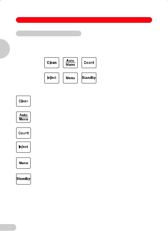
2 Device description
The FemtoJet® express enables minute quantities of liquid to be injected into cells. The relevant parameters (injection pressure pi and injection time ti) are set using the variable regulators. The key or connected hand or foot control or the INJECT key of the connected
micromanipulator are used to trigger these two parameters. If no injections are being performed, compensation pressure pc is applied permanently.
The connection of an external pressure supply enables faster injections, even with higher pressure.
2
description Device
55

2
Device description
2 Device description
2.1 Overview
1
2
3
4
1 Display
–Displays relevant parameters during injection or setting of parameters.
–Guides operator through functions.
2Keypad
–To trigger actions.
–To call up the function menu.
–To switch to and from Standby mode.
3Variable regulators
–To set parameters injection pressure pi, injection time ti and compensation pressure pc.
–To select functions and parameters in Function mode.
4Tube connection
–Connect the injection tube for the capillary holder to the device via the bayonet connection.
56

2 Device description
Standard accessories:
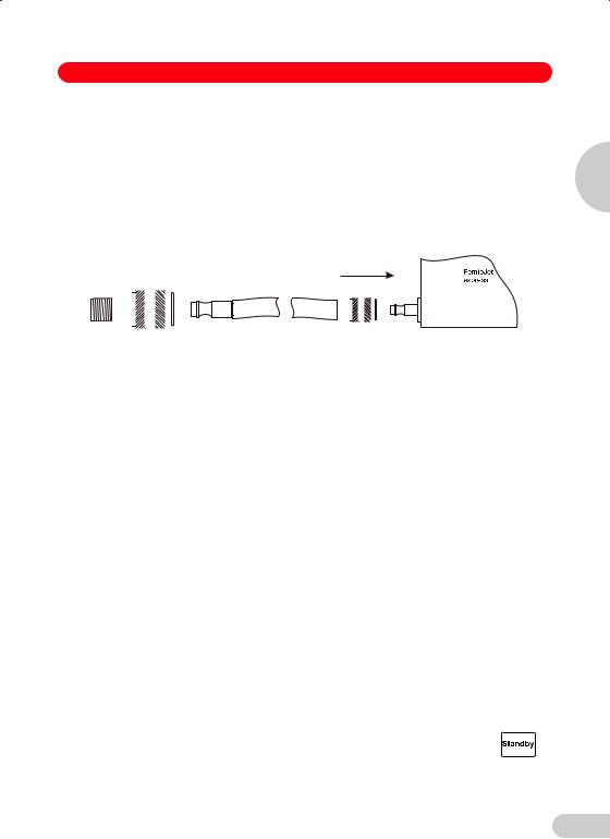
1 Pressure tube, 2,5 m, G 1/4-inch for external pressure supply incl. couplings 1 Injection tube, 2 m
1Universal capillary holder with grip head 0 for capillary diameters of 1.0 mm and adapter for Femtotips→
1 Hand control for triggering injection and the Clean function 1 Femtotips→, Femtotips→ II and Microloader
1 Mains cable
1 Operating manual
Optional accessories:
1 Foot control for triggering the Inject function
1 Connecting cable (Interface Cable 5171) to the Micromanipulator 5171 or InjectMan→
2
description Device
57
2 Device description
2.2 Short description
Display
Display of all relevant parameters and information.
2
Function keys
Device description
Clean
To apply the maximum pressure for cleaning the capillary to the tube outlet.
Auto / Manu
To switch between manual and automatic time-controlled injection.
Count
To reset to zero the counter for injections which have been actuated.
Inject
To execute automatic or manual injection.
Menu
To switch the device to menu control; selected functions may be executed.
Standby
When the key is pressed briefly:
To switch the device between operating mode and standby mode or vice versa.
When the key is held down:
As above, but also deairs the valve system.
58
2 Device description
Variable regulator
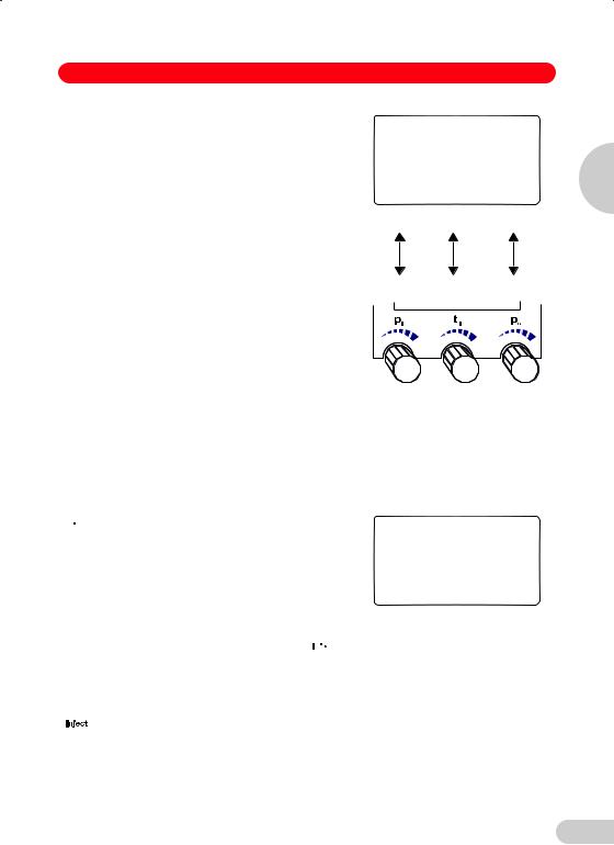
In the normal operating mode, the parameters for injection are set by the three variable regulators. The arrangement of the variable regulators corresponds to the arrangement of the parameters in the two bottom lines of the display:
From left to right: injection pressure pi, injection time ti and compensation pressure pc.
In other operating modes, the variable regulators have either the significance indicated in the display or no significance at all.
Tube connection
The injection tube for the capillary holder is connected to the device via the bayonet connection.
2
description Device
59

2 Device description
2.3 Startup
2
Device description
4
4
3 |
2 |
1 |
Fig. 2: Diagram of rear of device
–Electrical connection is effected via the mains socket with integrated mains switch (1).
–The connection to the external pressure supply (2) takes place via the delivered pressure tube, 2.5 m.
–Connection to an Eppendorf manipulator designed for injection is effected via the 15-pin interface (3).
–Optional switches (e.g. foot control, hand control) or a computer can be connected to the 9-pin interfaces (4).
60
2 Device description
Connection of the external pressure supply
Dry, non-oiled, compressed air or purified nitrogen gas is to be used!
Pressure range from 4000 hPa to a maximum of 8000 hPa (4 bar – 8 bar, 58 PSI – 116 PSI), constant pressure.
The connection for the external pressure supply is found on the rear side of the device. Remove the black plastic cap.
The delivered pressure tube can be connected directly to the device.
|
|
|
|
|
|
|
|
|
|
|
|
|
|
|
|
|
|
|
|
|
|
|
|
|
|
|
|
|
|
|
|
|
|
|
|
|
|
|
|
|
|
|
|
|
|
|
|
|
|
|
|
|
|
|
|
|
|
|
|
|
|
|
|
|
|
|
|
|
|
|
|
|
|
|
|
|
|
|
|
|
|
|
|
|
|
|
|
|
|
|
|
|
|
|
|
|
|
|
|
|
|
1 |
|
|
|
2 |
3 |
|
4 |
|||||||||
Fig. 3: pressure tube, 2.5 m
1Quick-lock coupling for mounting on the compressor, building pressure system (e.g. when no connection system is available in the lab)
2Plug sleeve, for coupling 1
3Quick-lock coupling for connection to the FemtoJet® express
4Plug sleeve to the FemtoJet® express, for coupling 3
The connection to the compressor, compressed air flask or building system can take place with the supplied lock coupling (G1/4-inch threaded) or must be adapted by building services to the existing connections.
The connection of the pressure tube to the high-pressure flasks, compressors or building pressure systems is not part of these operating instructions!
Switching on the device
Connect the device to the external pressure supply. The injection tube may not be connected when switching on and during the initialization phase.
Set the mains switch on the rear of the device to "I".
After being switched on, the unit runs through an initialization phase with self-test and valve adjustment. Duration of approx. 1 minute.
Switching off the device
If it is not going to be used for an extended period, the device is to be separated from the external pressure supply and to be depressurized via the switch-off routine using the key. Then switch off the device at the rear.
2
description Device
61

3
Mode of operation
3 Mode of operation
3.1 Display, variable regulators and keypad
Before operating the device for the first time, users should read this section carefully. This section describes operation of the device only. Handling of the injection capillaries is described in Section 3.3.
AUTO |
|
n= 0 |
pi= |
150 hPa |
|
Supply pressure |
5261 |
|
pi[hPa] |
ti[s] |
pc[hPa] |
150 |
0.2 |
50 |
AUTO |
2.15 |
n= 0 |
pi= |
PSI |
|
Supply pressure |
76.3 |
|
pi[PSI] |
ti[s] |
pc[PSI] |
2.15 |
0.2 |
0.72 |
Display
The display shows the following:
1st line:
injection mode AUTO or MANU,
counter n for number of injections performed
2nd line (bold):
The most-recently set parameter or relevant parameter
Middle line:
In the device, adjacent maximum system pressure ps.
Bottom lines:
Parameters which affect injection
Compensation pressure pc which is applied permanently in the normal mode is displayed as an actual measured value.
The arrangement of the three parameters shown, pi, ti, pc, corresponds to the arrangement of the variable regulators.
3.1.1 Setting the injection parameters
The injection parameters have to be adapted to the injection capillaries used and the cell type and liquid which are to be injected.
The following injection parameters can be set using the variable regulators:
Injection pressure |
pi |
0; 5 – 6,000 hPa |
(0.00; 0.07 – 87.0 psi) |
Injection time |
ti |
0.1 – 99.9 s |
|
Compensation pressure |
pc |
0; 5 – 6,000 hPa |
(0,00; 0.07 – 87.0 psi) |
The settings are in increments of 1 hPa/0.1 s. The display can show hPa or psi, as required. The setting and internal pressure conversion are always performed in hPa. Rounding for the display in psi can result in increments of 0.01 to 0.02 psi.
The display of pressure in psi varies according to the size of the value (e.g.: 9.99 may also appear in the display as 10.0).
Note:
An adjustment of pi or pc above the internally adjacent system pressure ps doesn't make sense. The values for pi, pc should lie at least 500 hPa (7.2 PSI) below the system pressure in order to ensure secure valve regulation.
Slight deviations between the nominal value (specified value) and displayed compensation pressure pc (actual value) may occur for technical reasons. The relevant value is the actual value measured.
62
3 Mode of operation
The following settings are used as a basis for initial |
AUTO |
|
n= 0 |
injection experiments using Femtotip® / Femtotip® II: |
|
||
|
|
|
|
|
pi= |
150 hPa |
|
Display: |
pi[hPa] |
ti[s] |
pc[hPa] |
|
150 |
0.5 |
50 |
pi |
left-hand variable regulator: |
150 hPa |
ti |
central variable regulator: |
0.5 s |
pc |
right-hand variable regulator: |
50 hPa |
|
|
Variable regulators: |
3.1.2 Variable regulators
The variable regulators are set so that when they are turned slowly, the values are changed by 1 hPa / 0.1 second per notch (0.01 – 0.02 psi).
If the regulators are turned faster, the values are altered in larger increments.
3.1.3 Keypad
 Inject
Performs automatic or manual injection. Automatic injection is controlled via the injection time ti, and the injection pressure pi is used. In the second line, injection time ti is counted down from the nominal value.
AUTO - INJECT n= 0
0.4 s
Supply pressure |
5261 |
|
pi[hPa] |
ti[s] |
pc[hPa] |
150 |
0.6 |
50 |
Manual injection is performed for as long as the  key is held down. Injection pressure pi is used. In the second line, injection time ti is counted upwards from 0.0.
If the FemtoJet® express is connected to the Eppendorf Micromanipulator InjectMan® NI 2, 5171 or Inject Man® the injection movement of the micromanipulator is also started via the  key. Both units then combine as a system to perform semi-automatic microinjection.
Alternatively, the INJECT key of the connected micromanipulator or the hand / foot control can be used.
If synchronization is set to "limit" (SYNC = LIMIT) in the INJECT function of the micromanipulator, semi-automatic injection can only be triggered via the micromanipulator.
3
operation of Mode
63

3
Mode of operation
3 Mode of operation
Clean
The maximum available pressure for cleaning is applied at the tube outlet for as long as the key is held down. Once the key is released, the pressure drops to compensation pressure pc again. The pressure curve is shown in the form of a bar.
Auto / Manu
To switch between manual and automatic, time-controlled injection.
In the case of manual injection, time is counted upwards from 0.0 seconds. The parameter ti is not displayed in the bottom two lines in order to emphasize that the time cannot be set via the variable regulators in this case.
Count
To reset to zero the counter for injections which have been actuated.
Menu
To switch the device to menu control; selected functions may be executed.
In the first line, FUNC indicates that the device is in the function menu and shows which function number is active.
The second line contains the function description (e.g. "Select pressure unit").
The third line requests an action (e.g. press the |
|
, |
|
||
key to change the pressure unit). |
|
|
Current status: [hPa] |
|
|
The two bottom lines show information about which action is assigned to which variable regulator
(e.g. other functions can be selected using left-hand variable regulator pi).
CLEAN n= 0
≡≡≡≡≡≡≡≡≡≡≡≡≡≡≡_____
Supply pressure |
5261 |
|
pi[hPa] |
ti[s] |
pc[hPa] |
150 |
0.2 |
50 |
MANU - INJECT |
n= 0 |
|
|
0.4 |
s |
Supply pressure |
5261 |
|
pi[hPa] |
|
pc[hPa] |
150 |
|
50 |
FUNC 1
Push Inject to select
Pressure Unit |
hPa PSI |
Turn pi to |
|
select function |
|
64

3 Mode of operation
Standby
in the case of a brief interruption
When key is pressed briefly:
The device switches to the Standby mode without deairing. The illumination of the display switches off. "STANDBY" appears in the display with the suffix "Supply pressure = rxyz" as a code for system pressure ps being maintained.
Application:
For temporary interruptions or use of 


 as a Reset function.
When key is pressed again:
The device is reactivated and runs through a warm-up routine. This lasts approximately one minute.
Standby
with deairing of pressure accumulator
Hold down the key (approx. 2 seconds; the display moves to "STANDBY"):
The device switches to the Standby mode. The valve system is completely deaired, the illumination of the display switches off.
In addition to WAIT, the display also instructs that the compressed air supply is to be separated from the device. At the same time, some of the system pressure is released in order to support this instruction.
A noise can be heard at this stage.
"STANDBY" appears in the display with the note "Supply pressure = x" (x ~ 0).
Application:
For correct shutdown, with deairing of the entire pressure system in the event of longer periods of non-use or standstill (weekend or storage) with subsequent switch-off using the mains switch.
Press the key again:
The device is reactivated and runs through the warm-up routine.
Reset
To reset the device to the initial mode by pressing the  key briefly or via the mains switch.
STANDBY
3
Supply pressure |
6789 |
operation of Mode
Hold standby to exhaust
WAIT
Close supply pressure |
|
Supply pressure |
5261 |
STANDBY
Supply pressure |
0 |
65
Loading...