


Installation, operation & maintenance instructions
IP152, Rev AD April 2012
Level
Mobrey
Vertical Controls
Series B |
Series X |
Series D |
For instructions specific to ATEX approved flameproof models in hazardous area installations, refer to accompanying leaflet IP152/SI Exd
www.emersonprocess.com

Level
Installation, operation & maintenance instructions
IP152, Rev AD April 2012
2
Installation, operation & maintenance instructions
IP152, Rev AD April 2012
Level
Mobrey vertical magnetic level controls
Principle of Operation
Switching is achieved with the Mobrey “three-magnet” system, giving snap-action “latch-on” switching.
Vertical movement of the primary magnet A in a glandless pressure tube simultaneously actuates magnets B & C to switch the contacts. The “three-magnet” system enables the primary magnet to pass on and actuate switch mechanisms at other levels. Switch mechanisms already actuated can not re-set until the return of the primary magnet actuates the magnet system once again.
The primary magnet is moved vertically in the
pressure tube by a float or displacer Diagrammatic detail of three magnet system mechanism which rises and falls with the liquid
level.
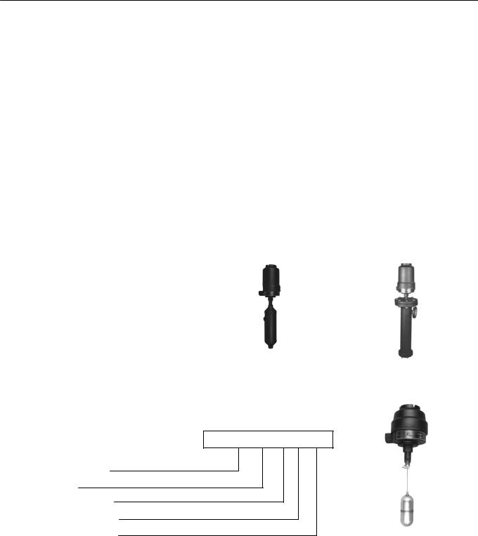
Identifying your control |
|
|
This manual covers the three series of controls: |
|
|
B, X and D as shown opposite. Your control |
|
|
has a part number stamped on the nameplate, |
|
|
an example of which is shown below. From this |
|
|
number you can identify your control and turn to |
SERIES B PAGES 5 & 6 |
SERIES X PAGES 5 & 6 |
|
|
|
the relevant pages in this manual. As switch |
|
|
mechanisms are common to all three series, |
|
|
electrical characteristics are given on page 4. |
|
|
XC 13F S7A 1 D8/112
Series & material of construction 
Float or displacer module
Enclosure module
No. of switch mechanisms
Type of switch mechanisms
Chamber or flange module
Controls manufactured to customer’s
requirements outside of our standard range will SERIES D PAGES 7 & 8 be numbered 707 / / and may be
identified according to the pictures above.
Displacer operated controls are covered in
Installation Instruction booklet IP153.
3

Level
Installation, operation & maintenance instructions
IP152, Rev AD April 2012
Electrical characteristics
4 Contact Type : D4, X4, P4, H4
2x independent SPST
AA make on rise : BB make on fall
8 Contact Type : D8, X8, P8, H8
Double pole double throw (4x independent SPST)
AA make on rise : BB make on fall
Note: For DPDT operation, installer must common any one pair of A and B wires in the terminal block for each of the two ends of the switch mechanism.
Wiring Examples
Single-switch Control
As high level alarm |
A |
|
Alarm ON |
|
|||
|
A |
|
|
|
|
|
|
|
B |
|
|
|
B |
|
|
As low level alarm |
A |
|
|
|
A |
|
|
|
B |
|
Alarm ON |
|
|
||
|
B |
|
|
|
|
|
|
|
|
|
Two-Switch Control
Combined Pump Control
And Low Level Alarm
Pump Control Switch |
A Pump ON |
||
|
A |
|
|
|
B |
|
|
|
|
|
|
|
B |
|
|
|
|
|
|
LLA Switch |
A |
|
|
A |
|
|
|
|
|
|
|
|
B |
|
Alarm ON |
|
|
||
|
B |
|
|
|
|
|
|
Two-switch Control
High and Low Level Alarm
HLA Switch |
A Alarm ON |
||
|
A |
|
|
|
B |
|
|
|
|
|
|
|
B |
|
|
|
|
|
|
LLA Switch |
A |
|
|
|
A |
|
|
|
B |
|
Alarm ON |
|
|
||
|
B |
|
|
|
|
|
|
Each switch mechanism has flying leads which are factory wired to ceramic terminal blocks fixed in the switch enclosure.
Electrical rating
|
Temp |
Low |
AC max. values |
|
AC max. values |
|
||||
Type |
wetside |
Temp |
|
|
|
|
|
|
Res |
Ind |
°C |
VA |
|
Volts |
Amps |
Watts |
Volts |
||||
|
use |
|
amps |
amps |
||||||
|
|
|
|
|
|
|
|
|||
|
|
|
|
|
|
|
|
|
|
|
D4, D8 |
400 |
Amp. |
2000 |
|
440 |
5 |
50 |
250 |
5 |
0.5 |
X4, X8 |
250 |
Amb. |
2000 |
|
440 |
10 |
50 |
250 |
10 |
0.5 |
P4, P8 |
400 |
Amb. |
6 |
|
250 |
0.25 |
3.6 |
250 |
0.25 |
0.1 |
H4, H8 |
250 |
-100°C |
2000 |
|
400 |
5 |
50 |
250 |
5 |
0.5 |
|
|
|
|
Power factor |
|
Time constant |
|
|||
|
|
|
|
|
0.4 mm |
|
|
40ms max. |
|
|
Warning
Gold plating on the contacts of the P4 and P8 switch mechanisms may be permanently damaged if the mechanisms are used to switch circuits with values greater than those shown above.
Important wiring notes
1.To minimize the electrical shock hazard, before energizing it is essential that the equipment is connected to a protective ground using the terminals supplied.
2.Switches must not be used for the direct starting of motors. Contacts should be wired in series with the operating coils of relays, contactor starters or solenoid valves, and fused separately.
3.The temperature of the switch enclosure may at times approach the temperature of the process and suitable heat resisting cables should therefore be used, together with appropriate cable glands.
4.A sufficient length of flexible cable should be fitted to allow easy removal of the switch head and displacer assembly at any time.
Flameproof models
5.Cable entry must be fitted with a flameproof cable entry device, with or without thread adaptor, and should be used in accordance with a local Code of Practice subject to agreement by the local Inspecting Authority.
6.U.L. Approved Applications: Use copper conductors 60°/75°C: 140°/167°F ONLY. Torque terminals to 6kg/cm: 7lb/in.
7.Ensure the cover locking safety grub screw is replaced and tightened before energizing.
Two switch pump control circuit using ‘holding’ relay for starters without auxiliary contacts.
Two switch pump control circuit using auxiliary contacts on starter.
Note diagram shows starter fitted with 250V coil for 3-phase 3-wire supply connect coil terminal N to line 1 and fit 440V coil.
4

Installation, operation & maintenance instructions
IP152, Rev AD April 2012
P4, P8, H4, H8 Switch Mechanisms - Simple Apparatus
Level
These Switch Mechanisms in a standard switch housing are classified as “Simple Apparatus” when used in Intrinsically Safe circuits. They comply with the requirements of EN60079-0, General Requirements and EN60079-11, clause 5.7 ‘Simple Apparatus’ and are not considered as a potential source of ignition for an explosive atmosphere.
They do not fulfill the definition of equipment in Article 1 (3) of Directive 94/9/EC (Equipment Explosive Atmospheres (ATEX) and are therefore outside the scope this Directive and do not have a Declaration of Conformity or CE mark related to this Directive.
When used as “Simple apparatus” within a hazardous atmosphere the following should be noted:
1.The product should be installed by suitably trained personnel, in accordance with the applicable code of practice.
2.As the product has no source of internal heating, the temperature classification is dependent on the ambient air temperature and the temperature of the process vessel to which it is attached.
3.Materials of construction: Refer to product catalogue or customer drawing for actual material of level switch concerned.
Housing and Cover: |
Carbon Steel, or Stainless Steel 316 type, or Aluminium Alloy LM25 or LM24 or |
|
B85 grd 360, or Cast Iron grd 250, or Gunmetal LG2 |
Pressure Tube & Union: |
Stainless Steel types 316, 321 or 304, or Carbon Steel 220M07, or Alloy NA18, |
|
or Alloy C-276 (UNS N10276) or Alloy 625 UNS N06625, or Alloy 825 UNS N08825 |
If the equipment is likely to come into contact with aggressive substances, it is the responsibility of the user to take suitable precautions that prevent it from being adversely affected, thus ensuring that the type of protection is not compromised.
Aggressive substances: e.g. acidic liquids or gases that may attack metals or solvents that may affect polymeric materials.
Suitable precautions: e.g. regular checks as part of routine inspections or establishing from the material’s data sheet that it is resistant to specific chemicals.
Note: The metallic alloy used for the enclosure material may be at the accessible surface of this equipment; in the event of rare accidents, ignition sources due to impact and friction sparks could occur. This shall be considered when the switch is being installed in locations that specifically require group II, category 1G equipment.
4.It is the responsibility of the user to ensure:
a.The joint requirements between the switch housing and vessel are compatible with the process media.
b.The joint tightness is correct for the joint material used.
c.That suitable temperature rated cable is used. Note: The cable entry temperature may exceed 70°C
d.The float is protected from impact or friction, or static electrical build-up from fast flowing non-conductive fluids, that could generate an ignition source.
5
 Loading...