


IS1x0105B
Emerson IS1x0105B, IS1x0023B, IS1x0043B, IS2x0200B, IS2x0170B User Manual
...
User Guide
Digistart IS
Soft starters for 3 phase
induction motors
7.5 to 800kW (23A to 1600A)
200V, 400V, 575V, 690V
0477-0001-04
www.controltechniques.com

General Information
The manufacturer accepts no liability for any consequences resulting from inappropriate, negligent or incorrect installation or
adjustment of the optional parameters of the equipment or from mismatching the starter with the motor.
The contents of this guide are believed to be correct at the time of printing. In the interests of commitment to a policy of continuous
development and improvement, the manufacturer reserves the right to change the specification of the product or its performance, or
the content of the guide without notice.
All rights reserved. No parts of this guide may be reproduced or transmitted in any form or by any means, electrical or mechanical
including, photocopying, recording or by an information storage or retrieval system, without permission in writing from the publisher.
Software Version
This product is supplied with the latest version of user-interface and machine control software. If this product is to be used in a new
or existing system with other starters, there may be some differences between their software and the software in this product. These
differences may cause the product to function differently. This may also apply to starters returned from the
Service Centre.
If there is any doubt, please contact Control Techniques or your local Distributor.
Environmental Statement
Control Techniques is committed to minimising
throughout their li
International Standard ISO 14001. Further information on the EMS, our Environment Policy and other relevant information is
available on request.
When the products eventually reach the end of their useful life, they can very easily be dismantled into their major component parts
for efficient recycling. Many parts snap together and can be separated without the use of tools, while other parts are secured with
conventional screws. Virtually all parts of the product are suitable for recycling.
Product packaging is of good quality and can be re-used. Large products are packed in wooden crates, while smaller products come
in strong cardboard cartons which themselves have a high recycled fibre content. If not re-used, these containers can be recycled.
Polythene, used on the protective film and bags from wrapping product, can be recycled in the same way. Control Techniques’s
packaging strategy favours easily recyclable materials of low environmental impact, and regular reviews identify opportunities for
improvement.
When preparing to recycle or dispose of any product or packaging, please observe local legislation and best practice.
REACH Legislation
EC Regulation 1907/2006 on the Registration, Evaluation, Authorisation and restriction of Chemicals (REACH) requires the supplier
of an article to inform the recipient if it contains more than a specified propo
European Chemicals Agency (ECHA) to be a Substance of Very High Concern (SVHC) and is therefore listed by them as a
candidate for compulsory authorisation.
For current information on how this requirement applies in relation to specific Control Techniques products, please approach your
usual contact in the first instance. Control Techniques position statement can be veiwed at:
www.controltechniques.com/REACH
fe cycle. To this end, we operate an Environmental Management System (EMS) which is certified to the
the environmental impacts of its manufacturing operations and of its products
rtion of any substance which is considered by the
Control Techniques
For the latest manuals and software, please visit our website.
Copyright © November 2011 Control Techniques Ltd
Issue: 4

Contents
1. Safety Information ............................................................................................................................................ 5
1.1 Warnings, cautions and notes ................................................................................................................................................ 5
1.2 Electrical safety - general warning .......................................................................................................................................... 5
1.3 System design and safety of personnel .................................................................................................................................. 5
1.4 Environmental limits ............................................................................................................................................................... 5
1.5 Compliance with regulations .................................................................................................................................................. 5
1.6 Motor ..................................................................................................................................................................................... 5
1.7 Adjusting parameters ............................................................................................................................................................. 5
1.8 Electrical installation .............................................................................................................................................................. 6
2. Rating Data ........................................................................................................................................................ 7
2.1 Model code ............................................................................................................................................................................ 7
2.2 Current ratings ....................................................................................................................................................................... 7
3. Mechanical Installation ................................................................................................................................... 12
3.1 Dimensions and weights ...................................................................................................................................................... 12
3.2 Physical installation .............................................................................................................................................................. 15
3.3 Busbar adjustment procedure .............................................................................................................................................. 15
4. Electrical Installation ...................................................................................................................................... 17
4.1 Terminal layout .................................................................................................................................................................... 17
4.2 Control connections ............................................................................................................................................................. 21
4.3 Power connections ............................................................................................................................................................... 22
4.4 Fuse information .................................................................................................................................................................. 26
4.5 Bypass contactor ................................................................................................................................................................. 30
4.6 Main contactor ..................................................................................................................................................................... 30
4.7 Circuit breaker ..................................................................................................................................................................... 30
4.8 Power factor correction ........................................................................................................................................................ 30
4.9 EMC (electromagnetic compatibility) .................................................................................................................................... 31
5. Keypad and Status .......................................................................................................................................... 32
5.1 Keypad ................................................................................................................................................................................ 32
5.2 Removing and replacing the keypad .................................................................................................................................... 32
5.3 Synchronising the keypad and the starter ............................................................................................................................ 33
5.4 Displays ............................................................................................................................................................................... 33
6. Quick Start Commissioning ........................................................................................................................... 35
6.1 Control wiring ....................................................................................................................................................................... 35
6.2 Setup procedure .................................................................................................................................................................. 36
7. Operation ......................................................................................................................................................... 37
7.1 Start, stop and reset commands........................................................................................................................................... 37
7.2 Soft start methods ................................................................................................................................................................ 37
7.3 Stop methods ....................................................................................................................................................................... 39
7.4 Jog operation ....................................................................................................................................................................... 42
7.5 Inside delta operation ........................................................................................................................................................... 43
8. Programming ................................................................................................................................................... 44
8.1 Programming menu ............................................................................................................................................................. 44
8.2 Access code ........................................................................................................................................................................ 44
8.3 Adjustment lock ................................................................................................................................................................... 45
8.4 Load defaults ....................................................................................................................................................................... 45
8.5 Quick setup details ............................................................................................................................................................... 45
8.6 Standard menu .................................................................................................................................................................... 46
8.7 Advanced menu ................................................................................................................................................................... 47
8.8 Parameter descriptions ........................................................................................................................................................ 51
8.9 Maintenance tools ................................................................................................................................................................ 65
9. Diagnostics ...................................................................................................................................................... 69
9.1 Protection responses ........................................................................................................................................................... 69
9.2 Trip messages ..................................................................................................................................................................... 69
9.3 General faults ...................................................................................................................................................................... 72
10. Application Examples ..................................................................................................................................... 74
10.1 Installation with main contactor ............................................................................................................................................ 74
10.2 Installation with external bypass contactor ........................................................................................................................... 75
10.3 Emergency run operation ..................................................................................................................................................... 76
10.4 Auxiliary trip circuit ............................................................................................................................................................... 77
Digistart IS User Guide 3
Issue: 4 www.controltechniques.com

10.5 DC brake with external zero speed sensor ........................................................................................................................... 78
10.6 Soft braking.......................................................................................................................................................................... 79
10.7 Two-speed motor ................................................................................................................................................................. 80
10.8 Slip-ring motor ..................................................................................................................................................................... 81
11. Technical Data ................................................................................................................................................. 82
12. Maintenance .................................................................................................................................................... 84
12.1 Care ..................................................................................................................................................................................... 84
12.2 Measuring the motor current ................................................................................................................................................ 84
12.3 Measuring the input and output power ................................................................................................................................. 84
12.4 Exchanging products ........................................................................................................................................................... 84
13. Options ............................................................................................................................................................ 85
4 Digistart IS User Guide
www.controltechniques.com Issue: 4

Safety
Information
Rating
Data
Mechanical
Installation
Electrical
Installation
Keypad
and
Status
Quick Start
Commissioning
Operation
Programming
Diagnostics
Application
Examples
Technical
Data
Maintenance
Options
WARNING
A Warning contains information which is essential for avoiding a safety hazard.
CAUTION
A Caution contains information which is necessary for avoiding a risk of damage to the product or other equipment.
NOTE
A Note contains information which helps to ensure correct operation of the product.
1. Safety Information
1.1 Warnings, cautions and notes
1.2 Electrical safety - general warning
The voltages used in the starter can cause severe electrical shock and/or burns, and could be lethal. Extreme care is necessary at
all times when working with or adjacent to the starter.
Specific warnings are given at the relevant places in this guide.
1.3 System design and safety of personnel
The starter is intended as a component for professional incorporation into complete equipment or a system. If installed incorrectly,
the starter may present a safety hazard.
The starter uses high voltages and currents, carries stored electrical energy, and is used to control equipment which can cause
injury.
Close attention is required to the electrical installation and the system design to avoid hazards either in normal operation or in the
event of equipment malfunction. System design, installation, commissioning and maintenance must be carried out by personnel who
have the necessary training and experience. They must read this safety information and this guide carefully.
None of the starter functions must be used to ensure safety of personnel, i.e. they must not be used for safety-related
functions.
Careful consideration must be given to the functions of the starter which might result in a hazard, either through their intended
behaviour or through incorrect operation due to a fault. In any application where a malfunction of the starter or its control system
could lead to or allow damage, loss or injury, a risk analysis must be carried out, and where necessary, further measures taken to
reduce the risk.
The system designer is responsible for ensuring that the complete system is safe and designed correctly according to the relevant
safety standards.
1.4 Environmental limits
Instructions regarding transport, storage, installation and use of the starter must be complied with, including the specified
environmental limits. Starters must not be subjected to excessive physical force.
1.5 Compliance with regulations
The installer is responsible for complying with all relevant regulations, such as national wiring regulations, accident prevention
regulations and electromagnetic compatibility (EMC) regulations. Particular attention must be given to the cross-sectional areas of
conductors, the selection of fuses or other protection, and protective ground connections.
Within the European Union, all machinery in which this product is used must comply with the following directives:
2006/42/EC: Safety of machinery.
2004/108/EC: Electromagnetic Compatibility.
1.6 Motor
Ensure the motor is installed in accordance with the manufacturer’s recommendations. Ensure the motor shaft is not exposed.
The values of the motor parameters set in the starter affect the protection of the motor. The default values in the starter should not
be relied upon. It is essential that the correct value is entered in Pr 1A Motor Full Load Current. This affects the thermal protection of
the motor.
1.7 Adjusting parameters
Some parameters have a profound effect on the operation of the starter. They must not be altered without careful consideration of
the impact on the controlled system. Measures must be taken to prevent unwanted changes due to error or tampering.
Digistart IS User Guide 5
Issue: 4 www.controltechniques.com

Safety
Information
Rating
Data
Mechanical
Installation
Electrical
Installation
Keypad
and
Status
Quick Start
Commissioning
Operation
Programming
Diagnostics
Application
Examples
Technical
Data
Maintenance
Options
1.8 Electrical installation
1.8.1 Electrical shock risk
The voltages present in the following locations can cause severe electric shock and may be lethal:
AC supply cables and connections
Output cables and connections
Many internal parts of the starter, and external option units
The AC supply must be disconnected from the starter using an approved isolation device before any cover is removed from the
starter or before any servicing work is performed.
Models IS3x0255B to IS4x1000B, IS4x0360N to IS561600N: The busbar and heatsink are live while the unit is operating (starting,
running or stopping). If the starter is installed without a main contactor, the busbar and heatsink are live whenever mains voltage is
connected (including when the starter is ready or tripped).
1.8.2 Power-up procedure
Always apply control voltage before (or with) mains voltage.
IS1x0023B to IS1x0105B: After transportation, mechanical shock or rough handling there is a possibility that the bypass contactor
may have latched into the on state. To prevent the possibility of the motor starting immediately, on first commissioning or operation
after transportation, always ensure that the control supply is applied before the power, so that the contactor state is initialised.
1.8.3 STOP function
The STOP function does not remove dangerous voltages from the starter, the motor or any external option units.
1.8.4 Stored charge
The starter contains capacitors that remain charged to a potentially dangerous voltage after the AC supply has been disconnected.
If the starter has been energised, the AC supply must be isolated at least two minutes before work may continue.
Normally, the capacitors are discharged by an internal resistor. Under certain, unusual fault conditions, the capacitors may fail to
discharge. Do not assume that the capacitors have discharged. To protect the user and the equipment, take due care when carrying
out any work on the starter.
1.8.5 Equipment supplied by plug and socket
The control supply terminals of the starter are connected to the internal capacitors through rectifier diodes which are not intended to
give safety isolation. If the plug terminals can be touched when the plug is disconnected from the socket, a means of automatically
isolating the plug from the starter must be used (e.g. a latching relay).
1.8.6 Short circuit
Digistart IS soft starters are not short circuit proof. After severe overload or short circuit, the operation of the soft starter should be
fully tested by an authorised service agent.
1.8.7 Auto-start
Use the auto-start feature with caution. Read all the notes related to auto-start before operation.
6 Digistart IS User Guide
www.controltechniques.com Issue: 4
Safety
Information
Rating
Data
Mechanical
Installation
Electrical
Installation
Keypad
and
Status
Quick Start
Commissioning
Operation
Programming
Diagnostics
Application
Examples
Technical
Data
Maintenance
Options
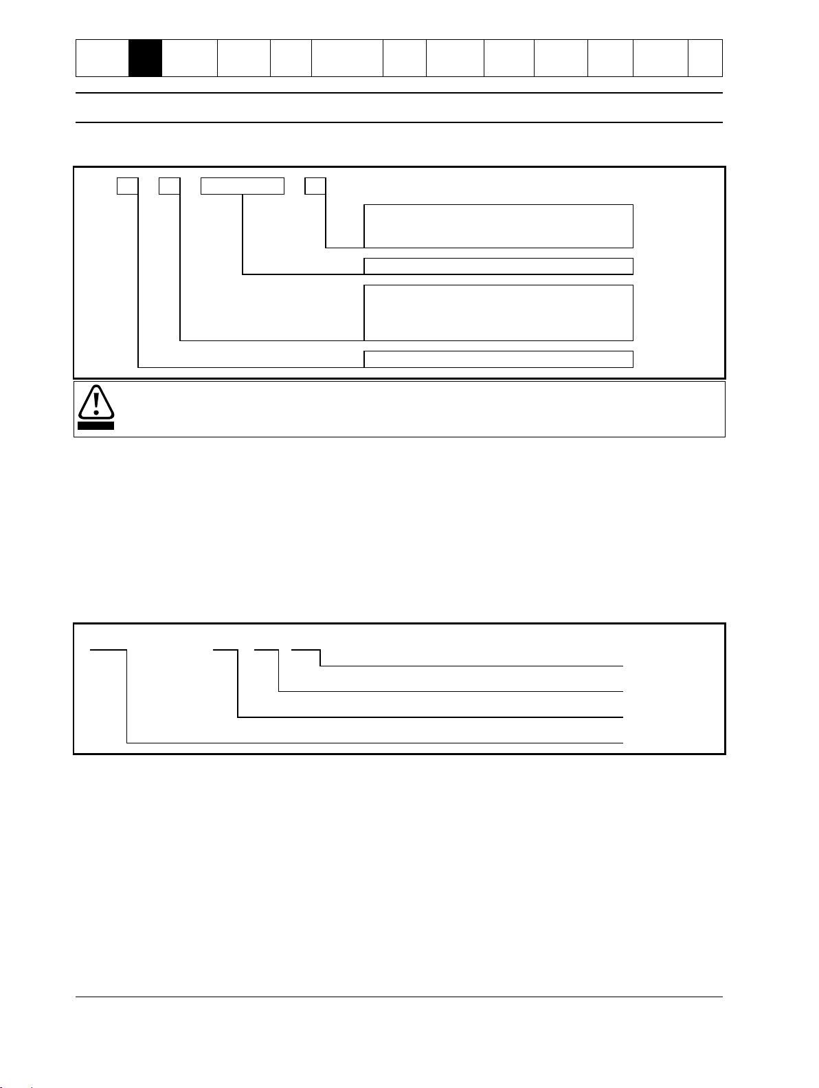
IS
3 4 0 2 5
5 N
Bypass
B = Internal
N = Non-bypassed
Nominal current rating
Mains voltage
4 = 200 to 440 Vac (± 10%)
6 = 380 to 600 Vac (± 10%) or 380 to 690 Vac
(± 10% for grounded star supply system only)
Frame size
CAUTION
Digistart IS can only be used on 690V IT supply equipped with surge protectors. Please contact Control Techniques or
your local distributor.
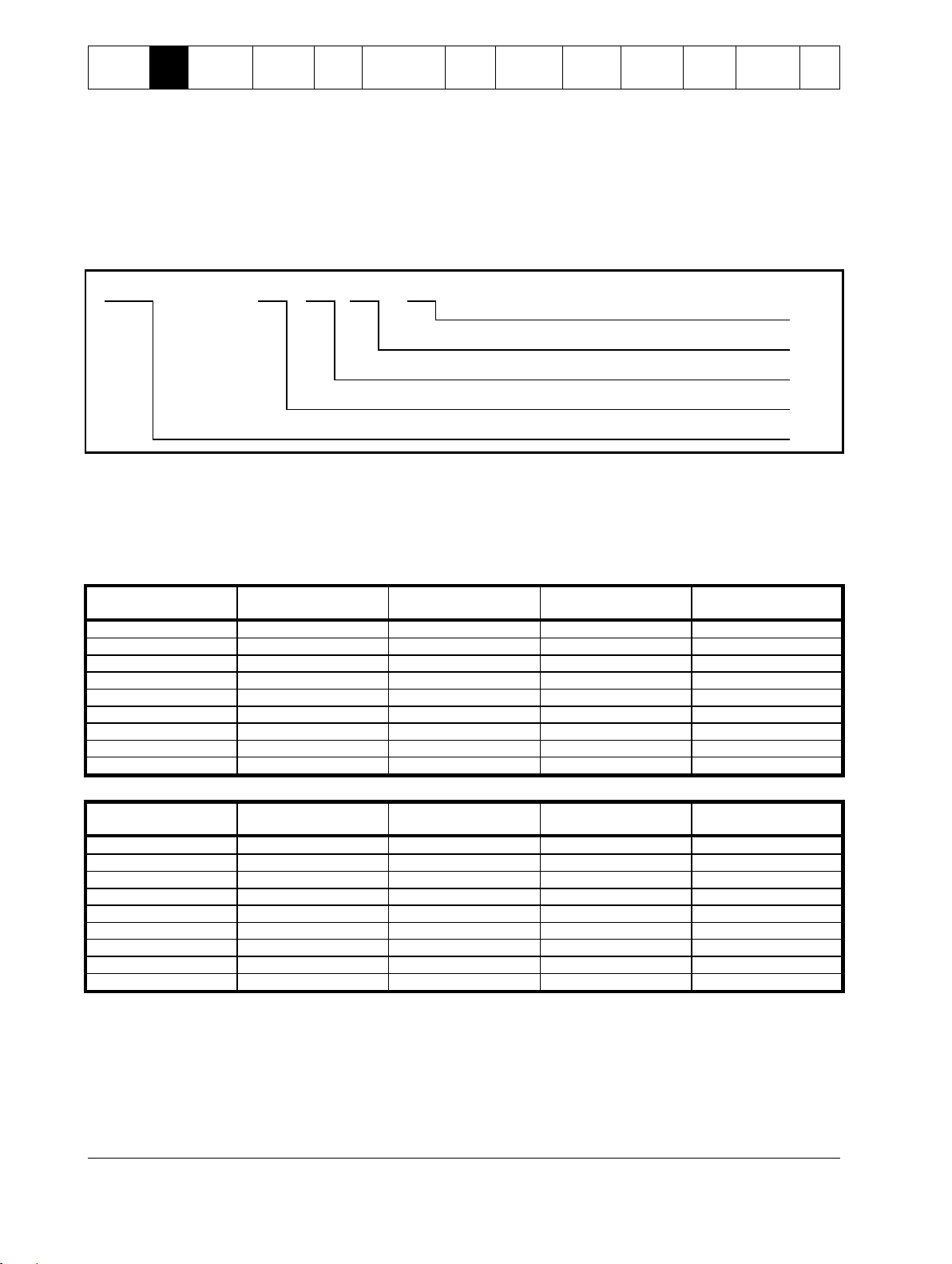
80 A : AC-53b
3.5 - 15 : 345
Off time (seconds)
Start time (seconds)
Start current (multiple of motor full load current)
Starter current rating (amperes)
2. Rating Data
2.1 Model code
Figure 2-1 Model code explanation
2.2 Current ratings
Contact your local supplier for ratings under operating conditions not covered by these ratings charts.
2.2.1 Current ratings for bypass operation
AC53b utilisation code
The AC53b utilisation code defines the current rating and standard operating conditions for a bypassed soft starter (internally
bypassed, or installed with an external bypass contactor).
The soft starter’s current rating determines the maximum motor size it can be used with. The soft starter's rating depends on the
number of starts per hour and the length and current level of the start.
The soft starter’s current rating is only valid when used within the conditions specified in the utilisation code. The soft starter may
have a higher or lower current rating in different operating conditions.
Figure 2-2 AC53b utilisation code
Starter current rating: The full load current rating of the soft starter given the parameters detailed in the remaining sections of the
utilisation code.
Start current: The maximum available start current.
Start time: The maximum allowable start time.
Off time: The minimum allowable time between the end of one start and the beginning of the next start.
Digistart IS User Guide 7
Issue: 4 www.controltechniques.com

Safety
Information
Rating
Data
Mechanical
Installation
Electrical
Installation
Keypad
and
Status
Quick Start
Commissioning
Operation
Programming
Diagnostics
Application
Examples
Technical
Data
Maintenance
Options
Model
AC53b 3.0-10:350
40 ºC <1000 metres
AC53b 3.5-15:345
40 ºC <1000 metres
AC53b 4.0-20:340
40 ºC <1000 metres
AC53b 4.5-30:330
40 ºC <1000 metres
IS1x0023B
23 A
20 A
17 A
15 A
IS1x0043B
43 A
37 A
31 A
26 A
IS1x0053B
53 A
53 A
46 A
37 A
Model
AC53b 3.0-10:590
40 ºC <1000 metres
AC53b 3.5-15:585
40 ºC <1000 metres
AC53b 4.0-20:580
40 ºC <1000 metres
AC53b 4.5-30:570
40 ºC <1000 metres
IS1x0076B
76 A
64 A
55 A
47 A
IS1x0097B
97 A
82 A
69 A
58 A
IS1x0105B
105 A
105 A
95 A
78 A
IS2x0145B
145 A
123 A
106 A
90 A
IS2x0170B
170 A
145 A
121 A
97 A
IS2x0200B
200 A
189 A
160 A
134 A
IS2x0220B
220 A
210 A
178 A
148 A
IS3x0255B
255 A
231 A
201 A
176 A
IS4x0350B
350 A
306 A
266 A
230 A
IS4x0425B
425 A
371 A
321 A
276 A
IS4x0500B
500 A
445 A
383 A
326 A
IS4x0700B
700 A
592 A
512 A
438 A
IS4x0820B
820 A
705 A
606 A
516 A
IS4x0920B
920 A
804 A
684 A
571 A
IS4x1000B
1000 A
936 A
796 A
664 A
For models IS3x0255N to IS561600N, these ratings are valid only when externally bypassed using a suitable contactor.
Model
AC53b 3.0-10:590
40 ºC <1000 metres
AC53b 3.5-15:585
40 ºC <1000 metres
AC53b 4.0-20:580
40 ºC <1000 metres
AC53b 4.5-30:570
40 ºC <1000 metres
IS3x0255N
255 A
231 A
201 A
176 A
IS4x0360N
360 A
360 A
310 A
263 A
IS4x0430N
430 A
430 A
368 A
309 A
IS4x0650N
650 A
650 A
561 A
455 A
IS4x0790N
790 A
790 A
714 A
579 A
IS4x0930N
930 A
930 A
829 A
661 A
IS561200N
1200 A
1200 A
1200 A
1071 A
IS561410N
1410 A
1410 A
1319 A
1114 A
IS561600N
1600 A
1600 A
1600 A
1353 A
NOTE
Table 2-1 Current ratings - in-line (3-wire) connection, bypassed operation
Table 2-2 Current ratings - in-line (3-wire) connection, externally bypassed
8 Digistart IS User Guide
www.controltechniques.com Issue: 4

Safety
Information
Rating
Data
Mechanical
Installation
Electrical
Installation
Keypad
and
Status
Quick Start
Commissioning
Operation
Programming
Diagnostics
Application
Examples
Technical
Data
Maintenance
Options
Model
AC53b 3.0-10:350
40 ºC <1000 metres
AC53b 3.5-15:345
40 ºC <1000 metres
AC53b 4.0-20:340
40 ºC <1000 metres
AC53b 4.5-30:330
40 ºC <1000 metres
IS1x0023B
34 A
30 A
26 A
22 A
IS1x0043B
64 A
59 A
51 A
44 A
IS1x0053B
79 A
79 A
69 A
55 A
Model
AC53b 3.0-10:590
40 ºC <1000 metres
AC53b 3.5-15:585
40 ºC <1000 metres
AC53b 4.0-20:580
40 ºC <1000 metres
AC53b 4.5-30:570
40 ºC <1000 metres
IS1x0076B
114 A
96 A
83 A
70 A
IS1x0097B
145 A
123 A
104 A
87 A
IS1x0105B
157 A
157 A
143 A
117 A
IS2x0145B
217 A
184 A
159 A
136 A
IS2x0170B
255 A
217 A
181 A
146 A
IS2x0200B
300 A
283 A
241 A
200 A
IS2x0220B
330 A
315 A
268 A
223 A
IS3x0255B
382 A
346 A
302 A
264 A
IS4x0350B
525 A
459 A
399 A
345 A
IS4x0425B
638 A
557 A
482 A
414 A
IS4x0500B
750 A
668 A
575 A
490 A
IS4x0700B
1050 A
889 A
768 A
658 A
IS4x0820B
1230 A
1058 A
910 A
774 A
IS4x0920B
1380 A
1206 A
1026 A
857 A
IS4x1000B
1500 A
1404 A
1194 A
997 A
For models IS3x0255N to IS561600N, these ratings are valid only when externally bypassed using a suitable contactor.
Model
AC53b 3.0-10:590
40 ºC <1000 metres
AC53b 3.5-15:585
40 ºC <1000 metres
AC53b 4.0-20:580
40 ºC <1000 metres
AC53b 4.5-30:570
40 ºC <1000 metres
IS3x0255N
382 A
346 A
302 A
264 A
IS4x0360N
540 A
540 A
465 A
395 A
IS4x0430N
645 A
645 A
552 A
464 A
IS4x0650N
975 A
975 A
842 A
683 A
IS4x0790N
1185 A
1185 A
1071 A
868 A
IS4x0930N
1395 A
1395 A
1244 A
992 A
IS561200N
1800 A
1800 A
1800 A
1606 A
IS561410N
2115 A
2115 A
1979 A
1671 A
IS561600N
2400 A
2400 A
2400 A
2030 A
NOTE
Table 2-3 Current ratings - inside delta (6-wire) connection, bypassed operation
Table 2-4 Current ratings - inside delta (6-wire) connection, externally bypassed
Digistart IS User Guide 9
Issue: 4 www.controltechniques.com
Safety
Information
Rating
Data
Mechanical
Installation
Electrical
Installation
Keypad
and
Status
Quick Start
Commissioning
Operation
Programming
Diagnostics
Application
Examples
Technical
Data
Maintenance
Options
351 A
:
AC-53a
3.5 - 15 : 50 - 6
Starts per hour
On-load duty cycle (%)
Start time (seconds)
Start current (multiple of motor full load current)
Starter current rating (amperes)
Model
AC53a 3-10:50-6
40 ºC <1000 metres
AC53a 3.5-15:50-6
40 ºC <1000 metres
AC53a 4-20:50-6
40 ºC <1000 metres
AC53a 4.5-30:50-6
40 ºC <1000 metres
IS3x0255N
255 A
222 A
195 A
171 A
IS4x0360N
360 A
351 A
303 A
259 A
IS4x0430N
430 A
413 A
355 A
301 A
IS4x0650N
650 A
629 A
532 A
437 A
IS4x0790N
790 A
790 A
694 A
567 A
IS4x0930N
930 A
930 A
800 A
644 A
IS561200N
1200 A
1200 A
1135 A
983 A
IS561410N
1410 A
1355 A
1187 A
1023 A
IS561600N
1600 A
1600 A
1433 A
1227 A
Model
AC53a 3-10:50-6
40 ºC <1000 metres
AC53a 3.5-15:50-6
40 ºC <1000 metres
AC53a 4-20:50-6
40 ºC <1000 metres
AC53a 4.5-30:50-6
40 ºC <1000 metres
IS3x0255N
382 A
334 A
293 A
257 A
IS4x0360N
540 A
527 A
455 A
388 A
IS4x0430N
645 A
620 A
533 A
451 A
IS4x0650N
975 A
943 A
798 A
656 A
IS4x0790N
1185 A
1185 A
1041 A
850 A
IS4x0930N
1395 A
1395 A
1200 A
966 A
IS561200N
1800 A
1800 A
1702 A
1474 A
IS561410N
2115 A
2033 A
1780 A
1535 A
IS561600N
2400 A
2400 A
2149 A
1840 A
2.2.2 Current ratings for continuous operation (not bypassed)
AC53a utilisation code
The AC53a Utilisation Code defines the current rating and standard operating conditions for a non-bypassed soft starter.
The soft starter’s current rating determines the maximum motor size it can be used with. The soft starter's rating depends on the
number of starts per hour, the length and current level of the start, and the percentage of the operating cycle that the soft starter will
be running (passing current).
The soft starter’s current rating is only valid when used within the conditions specified in the utilisation code. The soft starter may
have a higher or lower current rating in different operating conditions.
Figure 2-3 AC53a utilisation code
Starter current rating: The full load current rating of the soft starter given the parameters detailed in the remaining sections of the
utilisation code.
Start current: The maximum available start current.
Start time: The maximum allowable start time.
On-load duty cycle: The maximum percentage of each operating cycle that the soft starter can operate.
Starts per hour: The maximum allowable number of starts per hour.
Table 2-5 Current ratings - in-line (3-wire) connection, non-bypassed operation
Table 2-6 Current ratings - inside delta (6-wire) connection, non-bypassed operation
10 Digistart IS User Guide
www.controltechniques.com Issue: 4

Safety
Information
Rating
Data
Mechanical
Installation
Electrical
Installation
Keypad
and
Status
Quick Start
Commissioning
Operation
Programming
Diagnostics
Application
Examples
Technical
Data
Maintenance
Options
In-line connection
Inside delta connection
Model
Minimum
Maximum
Minimum
Maximum
IS1x0023B
5 A
23 A
5 A
34 A
IS1x0043B
9 A
43 A
9 A
64 A
IS1x0053B
11 A
53 A
11 A
79 A
IS1x0076B
15 A
76 A
15 A
114 A
IS1x0097B
19 A
97 A
19 A
145 A
IS1x0105B
21 A
105 A
21 A
157 A
IS2x0145B
29 A
145 A
29 A
217 A
IS2x0170B
34 A
170 A
34 A
255 A
IS2x0200B
40 A
200 A
40 A
300 A
IS2x0220B
44 A
220 A
44 A
330 A
IS3x0255B
51 A
255 A
51 A
382 A
IS4x0350B
70 A
350 A
70 A
525 A
IS4x0425B
85 A
425 A
85 A
638 A
IS4x0500B
100 A
500 A
100 A
750 A
IS4x0700B
140 A
700 A
140 A
1050 A
IS4x0820B
164 A
820 A
164 A
1230 A
IS4x0920B
184 A
920 A
184 A
1380 A
IS4x1000B
200 A
1000 A
200 A
1500 A
In-line connection
Inside delta connection
Model
Minimum
Maximum
Minimum
Maximum
IS3x0255N
51 A
255 A
51 A
382 A
IS4x0360N
72 A
360 A
72 A
540 A
IS4x0430N
86 A
430 A
86 A
645 A
IS4x0650N
130 A
650 A
130 A
975 A
IS4x0790N
158 A
790 A
158 A
1185 A
IS4x0930N
186 A
930 A
186 A
1395 A
IS561200N
240 A
1200 A
240 A
1800 A
IS561410N
282 A
1410 A
282 A
2115 A
IS561600N
320 A
1600 A
320 A
2400 A
2.2.3 Minimum and maximum current settings
The Digistart IS's minimum and maximum full load current settings depend on the model:
Table 2-7 Minimum and maximum current settings, internally bypassed models
Table 2-8 Minimum and maximum current settings, externally bypassed models
Digistart IS User Guide 11
Issue: 4 www.controltechniques.com

Safety
Information
Rating
Data
Mechanical
Installation
Electrical
Installation
Keypad
and
Status
Quick Start
Commissioning
Operation
Programming
Diagnostics
Application
Examples
Technical
Data
Maintenance
Options
3. Mechanical Installation
WARNING
Digistart IS models IS2x0145B to IS561600N weigh in excess of 15 kg (33 lb). Use appropriate safeguards when lifting
these models.
WARNING
Models IS2x0145B to IS4x1000B and IS3x0255N to IS561600N are intended to be mounted in an enclosure which
prevents access except by trained and authorised personnel, and which prevents the ingress of contamination. The
complete range is designed for use in an environment classified as Pollution Degree 3 in accordance with IEC60664-1.
This means conductive pollution or dry, non-conductive pollution which becomes conductive due to condensation is
acceptable.
It is the installer's responsibility to ensure that any enclosure which allows access to models IS2x0145B to IS4x1000B
and IS3x0255N to IS561600N while the product is energized, provides protection against contact and ingress
requirements of IP20.
Models IS2x0145B to IS3x0255B can be installed with optional finger guards, in which case they do not need to be
mounted in an enclosure.
For further details on Digistart IS dimensions and corresponding CAD drawings please visit ww.controltechniques.com.
Model
Size
A
mm (in)
B
mm (in)
C
mm (in)
D
mm (in)
E
mm (in)
F
mm (in)
G
mm (in)
H
mm (in)
I
mm (in)
Weight
kg
(lb)
IS1x0023B
IS1x0043B
196.2
3.2
IS1x0053B
G1B
156.4
124.0
294.6
278.0
(7.72)
(7.05)
IS1x0076B
(6.16)
(4.88)
(11.60)
(10.94)
N/A
N/A
N/A
N/A
3.5 (7.22)
IS1x0097B
226.7
4.8
IS1x0105B
(8.92)
(10.58)
IS2x0145B
IS2x0170B
G2B
282
250
438
380
254
N/A
N/A
N/A
N/A
16
IS2x0200B
(11.10)
(9.84)
(17.24)
(14.96)
(10.00)
(35.27)
IS2x0220B
IS3x0255B
G3B
424
(16.54)
376
(14.8)
440
(17.32)
392
(15.43)
298
(11.73)
N/A
N/A
N/A
N/A
26
(57.2)
IS4x0350B
IS4x0425B
IS4x0500B
438
320
640
600
300
60.0
IS4x0700B
G4B
(17.24)
(12.60)
(25.20)
(23.62)
(11.81)
N/A
N/A
N/A
N/A
(132.3)
IS4x0820B
IS4x0920B
IS4x1000B
IS3x0255N
G3N
394 (15.51)
320 (12.60)
460 (18.11)
400 (15.75)
284 (11.18)
N/A
N/A
N/A
N/A
25 (55.12)
IS4x0360N
50.5
IS4x0430N
430
320
689
522
302
104.5
104.5
5.5
8.5
(111.33)
IS4x0650N
G4N
(16.93)
(12.60)
(27.12)
(20.55)
(11.89)
(4.11)
(4.11)
(0.22)
(0.33)
53.5
IS4x0790N
(117.95)
IS4x0930N
IS561200N
IS561410N
G5N
574
500
750
727
364
132.5
129 5 8.5
140
IS561600N
(22.60)
(19.69)
(29.53)
(28.62)
(14.33)
(5.22)
(5.08)
(0.20)
(0.33)
(308.65)
NOTE
3.1 Dimensions and weights
12 Digistart IS User Guide
www.controltechniques.com Issue: 4

Safety
Information
Rating
Data
Mechanical
Installation
Electrical
Installation
Keypad
and
Status
Quick Start
Commissioning
Operation
Programming
Diagnostics
Application
Examples
Technical
Data
Maintenance
Options
NOTE
Dimensions F, G and H are the additional space required for the output and input busbars, in addition to the overall
chassis measurement (C).
Figure 3-1 Unit dimensions (bypassed models)
D3-1x-0023-B, D3-1x-0043-B, D3-1x-0053-B
D3-1x-0076-B, D3-1x-0097-B, D3-1x-105-B
D3-1x-0145-B, D3-1x-0170-B, D3-1x-0200-B, D3-1x-0220-B
D3-1x-0255-B
D3-1x-0350-B, D3-1x-0425-B, D3-1x-0500-B, D3-1x-0700-B
D3-1x-0820-B, D3-1x-0920-B, D3-1x-1000-B
A
B
CED
08337.D
A
B
C
E
D
A
B
C
E
D
Digistart IS User Guide 13
Issue: 4 www.controltechniques.com

Safety
Information
Rating
Data
Mechanical
Installation
Electrical
Installation
Keypad
and
Status
Quick Start
Commissioning
Operation
Programming
Diagnostics
Application
Examples
Technical
Data
Maintenance
Options
Figure 3-2 Unit dimensions (non-bypassed models)
D3-1x-0255-N
D3-1x-0360-N, D3-1x-0430-N, D3-1x-0650-N, D3-1x-0790-N
D3-1x-0930-N, D3-16-1200-N, D3-16-1410-N, D3-16-1600-N
A
13511.A
A
B
B
E
E
CCD
D
F
I
G
H
14 Digistart IS User Guide
www.controltechniques.com Issue: 4

Safety
Information
Rating
Data
Mechanical
Installation
Electrical
Installation
Keypad
and
Status
Quick Start
Commissioning
Operation
Programming
Diagnostics
Application
Examples
Technical
Data
Maintenance
Options
3.2 Physical installation
1
3 4
2
08338.A
1
IS1x0023B to IS2x0220B: Allow 100 mm (3.94 in) between soft starters.
IS3x0255B to IS4x1000B: Allow 200 mm (7.88 in) between soft starters.
IS3x0255N: Allow 100 mm (3.94 in) between soft starters.
IS4x0360N to IS561600N: Allow 200 mm (7.88 in) between soft starters.
2
IS1x0023B to IS2x0220B: Allow 50 mm (1.97 in) between the soft starter and solid surfaces.
IS3x0255B to IS4x1000B: Allow 200 mm (7.88 in) between the soft starter and solid surfaces.
IS3x0255N: Allow 100 mm (3.94 in) between the soft starter and solid surfaces.
IS4x0360N to IS561600N: Allow 200 mm (7.88 in) between the soft starter and solid surfaces.
3
Soft starters may be mounted side by side with no clearance (that is, if mounted without communications modules).
4
The soft starter may be mounted on its side. Derate the soft starter's rated current by 15%.
WARNING
It is the user's responsibility to follow these instructions correctly. Control Techniques cannot be held responsible for
any damage to the starter or associated equipment from incorrect practice.
Input/Output
Output
Input
08350 .A
Input/Output
Input
Output
Figure 3-3 Mounting clearances
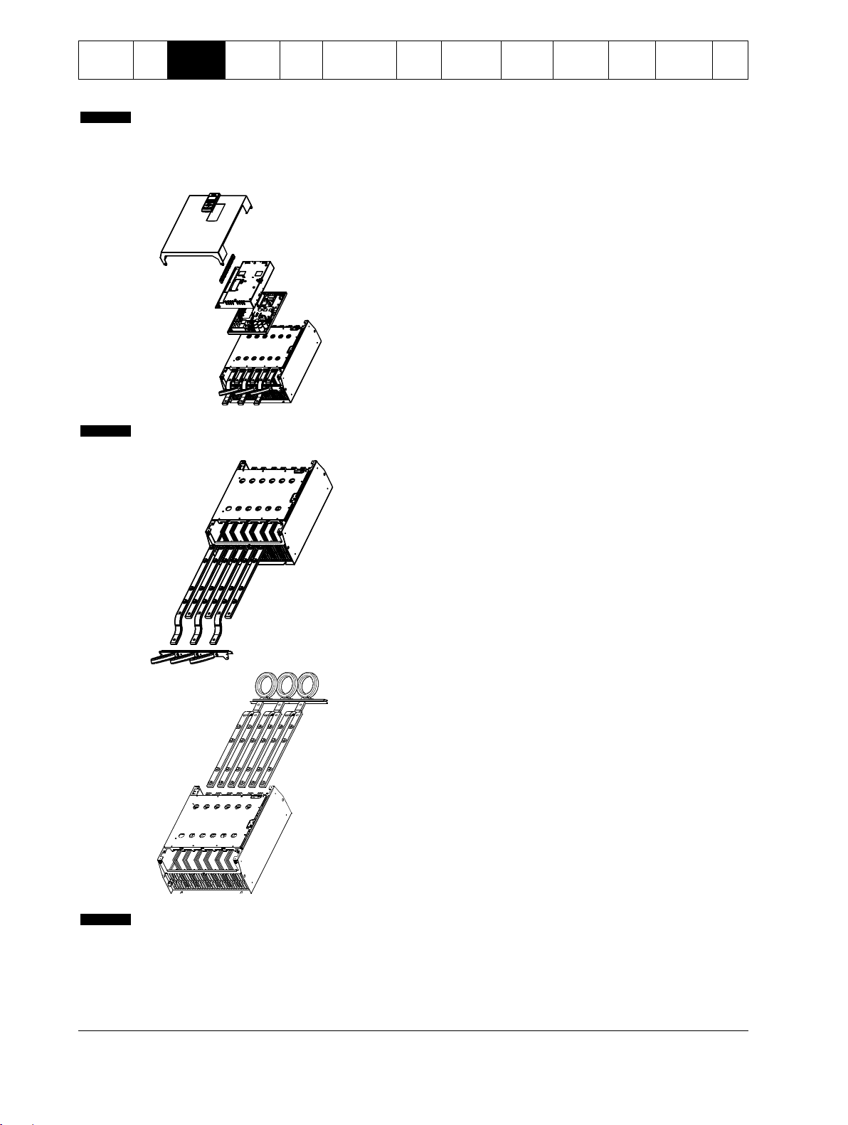
3.3 Busbar adjustment procedure
The busbars on non-bypassed models IS4x0360N to IS561600N can be adjusted for top or bottom input and output as required.
Figure 3-4 Busbar configuration options
Digistart IS User Guide 15
Issue: 4 www.controltechniques.com
Safety
Information
Rating
Data
Mechanical
Installation
Electrical
Installation
Keypad
and
Status
Quick Start
Commissioning
Operation
Programming
Diagnostics
Application
Examples
Technical
Data
Maintenance
Options
NOTE
Many electronic components are sensitive to static electricity. Voltages so low that they cannot be felt, seen or heard,
can reduce the life, affect performance, or completely destroy sensitive electronic components. When performing
service, proper ESD equipment should be used to prevent possible damage from occurring.
08604.A
1. Remove all wiring and links from the soft starter before
dismantling the unit.
2. Remove the unit cover (4 screws).
3. Remove the keypad faceplate, then gently remove the
keypad (2 screws).
4. Remove the control terminal plugs.
5. Gently fold the main plastic away from the starter (12
screws).
6. Unplug the keypad loom from CON 1 (see note).
7. Label each SCR firing loom with the number of the
corresponding terminal on the backplane PCB, then unplug
the looms.
8. Unplug the thermistor, fan and current transformer wires
from the model board.
9. Remove the plastic tray from the starter (four screws).
NOTE
Remove the main plastic slowly to avoid damaging the keypad wiring loom which runs between the main plastic and the
backplane PCB.
08605.A
10. Unscrew and remove the magnetic bypass plates (models
IS4x0430N to IS561600N only).
11. Remove the current transformer assembly (three screws).
12. Identify which busbars are to be moved. Remove the bolts
holding these busbars in place then slide the busbars out
through the bottom of the starter (four bolts per busbar).
08606.A
13. Slide the busbars in through the top of the starter. For input
busbars, the short curved end should be outside the starter.
For output busbars, the unthreaded hole should be outside
the starter.
14. Replace the dome washers with the flat face towards the
busbar, then tighten the bolts holding the busbars in place to
20 Nm.
15. Place the current transformer assembly over the input
busbars and screw the assembly to the body of the starter
(see note).
16. Run all wiring to the side of the starter and secure with cable
ties.
NOTE
If moving the input busbars, the current transformers (CTs) must also be reconfigured.
1. Label the CTs L1, L2 and L3 (L1 is leftmost when looking from the front of the starter). Remove the cable ties and
unscrew the CTs from the bracket.
2. Move the CT bracket to the top of the starter. Position the CTs for the correct phases, then screw the CTs to the
bracket. For models IS4x0360N to IS4x0930N, the CTs must be placed on an angle (the left hand legs of each CT
will be on the top row of holes and the right hand legs will be on the bottom tabs).
All units are manufactured with input and output busbars at the bottom of the unit as standard. The input and/or output busbars can
be moved to the top of the unit if required.
16 Digistart IS User Guide
www.controltechniques.com Issue: 4

Safety
Information
Rating
Data
Mechanical
Installation
Electrical
Installation
Keypad
and
Status
Quick Start
Commissioning
Operation
Programming
Diagnostics
Application
Examples
Technical
Data
Maintenance
Options
WARNING
Always apply control voltage before (or with) mains voltage.
WARNING
Always follow the specified tightening torque for all power and ground terminal connections.
NOTE
Some units use aluminium bus bars. When connecting power terminations, we recommend cleaning the surface contact
area thoroughly (using an emery or stainless steel brush) and using an appropriate jointing compound to prevent
corrosion.
NOTE
For personnel safety, the power terminals on models up to IS1x0105B are protected by snap-off tabs. When using large
cables, it may be necessary to break off these tabs.
Models which are internally bypassed do not require an external bypass contactor.
4. Electrical Installation
For specifications and detailed technical data, see Technical Data on page 82.
4.1 Terminal layout
4.1.1 Power terminations
Use only copper stranded or solid conductors, rated for 75 ºC.
Digistart IS User Guide 17
Issue: 4 www.controltechniques.com

Safety
Information
Rating
Data
Mechanical
Installation
Electrical
Installation
Keypad
and
Status
Quick Start
Commissioning
Operation
Programming
Diagnostics
Application
Examples
Technical
Data
Maintenance
Options
IS1x0023B to IS1x0105B
IS2x0145B
Power (L1/T1, L2/T2, L3/T3)
8.5 Nm (6.3 ft-lb)
11290.A
11291.A
14 (0.55)
mm (in)
5-60 (10-1/0)
mm2 (AWG)
Torx
T20 x 150
Torque =
4 Nm
2.9 Ft-lb
Flat
7mm x 150
Torque =
4 Nm
2.9 Ft-lb
IS2x0170B to IS2x0220B
IS3x0255B
8.5 Nm (6.3 ft-lb)
38 Nm (28.5 ft-lb)
5 mm
28 mm
11 mm
131 81.A
IS4x0350B to IS4x1000B
IS3x0255N
38 Nm (28.5 ft-lb)
17 Nm (12.5 ft-lb)
6 mm
32 mm
11 mm
098 66.A
6 mm
32 mm
10.5 mm
08353. A
IS4x0360N to IS4x0930N
IS561200N to IS561600N
38 Nm (28.5 ft-lb)
58 Nm (42.7 ft-lb)
13 mm32 mm
10.5 mm
08354. A
NOTE
Internally bypassed models IS4x0350B to IS4x1000B have input and output busbars at both the top and bottom of the
unit. The IS3x0255B is different, with input only busbars at the top of the unit. It can be mounted 'Top in, Bottom out' or
'Bottom in, Bottom out'. These busbars do not need to be adjusted.
Figure 4-1 Cable sizes, busbar dimensions and maximum torque settings
4.1.2 Ground terminals
Ground terminals are located at the back of the soft starter.
IS1x0023B to IS1x0105B have one terminal on the input side (top).
IS2x0145B to IS4x1000B and IS3x0255N to IS561600N have two terminals, one on the input side (top) and one on the
output side (bottom).
The ground terminal may also be used for a ground shield connection if necessary.
18 Digistart IS User Guide
www.controltechniques.com Issue: 4
Safety
Information
Rating
Data
Mechanical
Installation
Electrical
Installation
Keypad
and
Status
Quick Start
Commissioning
Operation
Programming
Diagnostics
Application
Examples
Technical
Data
Maintenance
Options
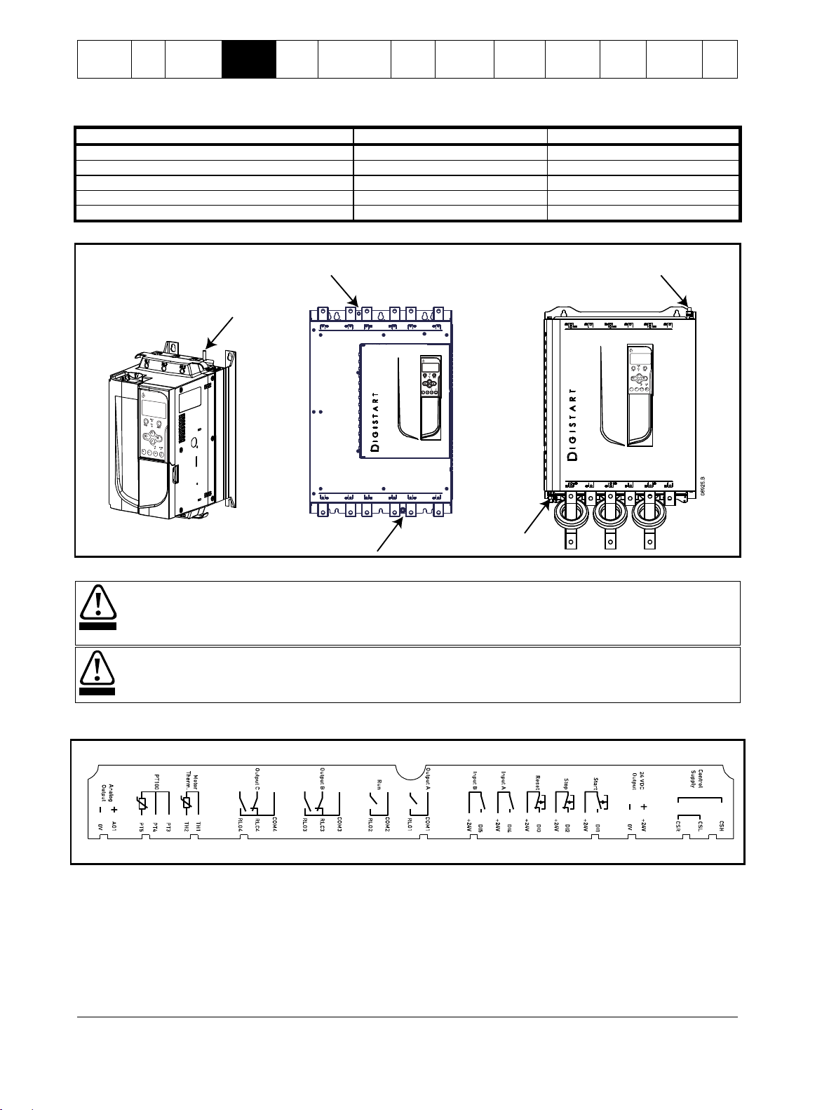
Tighten the cables as follows:
Models
Terminal size
Torque
IS1x0023B to IS1x0105B
M6
3 Nm
IS2x0145B to IS3x0255B
M8
5 Nm
IS3x0255N
M8
5 Nm
IS4x0350B to IS4x1000B
M10
8.5 Nm
IS4x0360N to IS561600N
M10
8.5 Nm
IS1x0023B to IS1x0105B
IS3x0255B to IS4x1000B
IS2x0145B to IS2x0220B and IS3x0255N to
IS561600N
CAUTION
Always connect control voltage to the correct terminals:
110 to 210 Vac: CSL-CSR or
220 to 440 Vac: CSH-CSR
WARNING
The installer must ensure that the external control circuits are insulated from human contact by at least one layer of
insulation (supplementary insulation) rated for use at the AC supply voltage.
08339.A
220~440VAC
110~210VAC
Table 4-1 Ground terminal maximum torque settings
Figure 4-2 Ground terminal locations
4.1.3 Control terminals
Control terminations use 2.5mm2 plug-in terminal blocks. Unplug each block, complete the wiring, then reinsert the block.
Figure 4-3 Control terminal layout
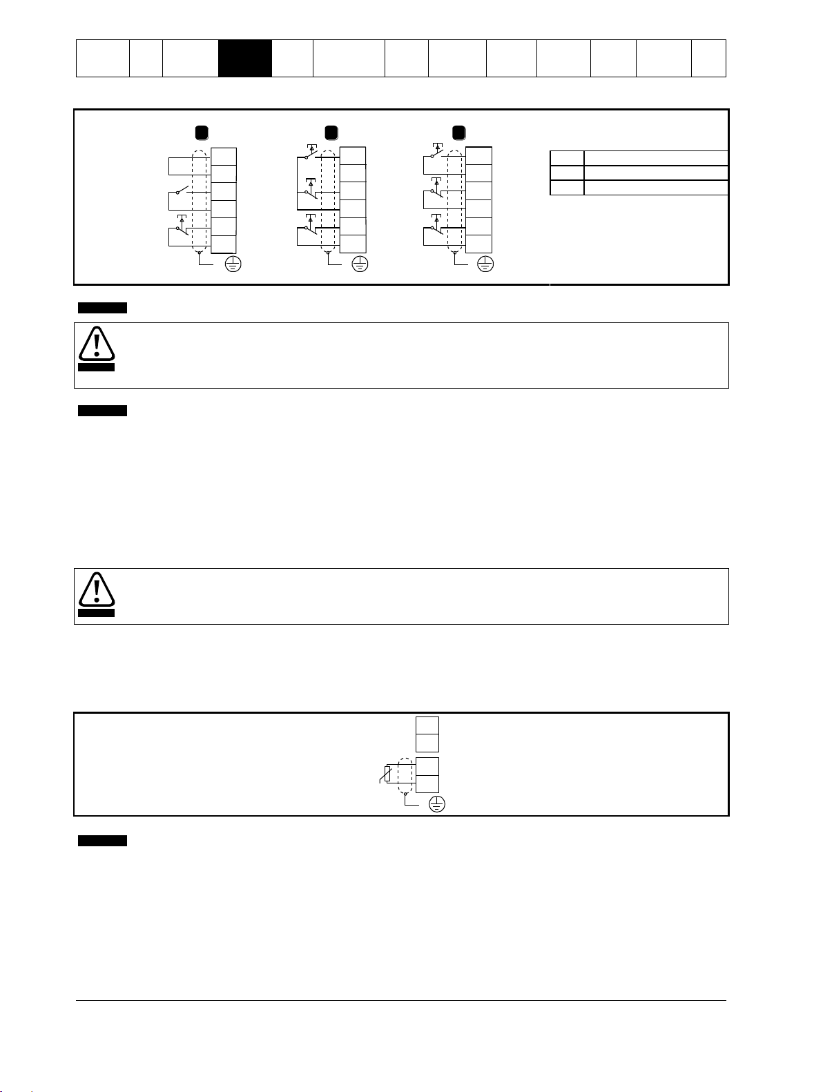
4.1.4 Start/Stop control logic
The Digistart IS has three fixed inputs for remote control. These inputs should be controlled by contacts rated for low voltage, low
current operation (gold flash or similar).
The maximum cable run is determined by the type of cable used, provided the maximum resistance of this cable does not exceed
100 Ohms. The cables must be twisted in pairs and shielded. The shield must be grounded at one end only, that is, at the soft
starter end. To avoid any EMC disturbance from the motor power cables, the thermistor cable must be separated from the motor
power cables by a minimum parallel distance of 300 mm.
Digistart IS User Guide 19
Issue: 4 www.controltechniques.com
Safety
Information
Rating
Data
Mechanical
Installation
Electrical
Installation
Keypad
and
Status
Quick Start
Commissioning
Operation
Programming
Diagnostics
Application
Examples
Technical
Data
Maintenance
Options
1 2 3
+24V
DI2
+24V
DI1
+24V
DI3
E E E
+24V
DI2
+24V
DI1
+24V
DI3
+24V
DI2
+24V
DI1
+24V
DI3
08340.A
Start/stop
Reset
Start
Stop
Reset
Start
Stop
Reset
1 Two-wire control
2
Three-wire control
3
Four-wire control
NOTE
For comprehensive information on control connection, see Control connections on page 21.
CAUTION
Do not apply voltage to the control input terminals. These are active 24 Vdc inputs and must be controlled with potential
free contacts.
Cables to the control inputs must be segregated from mains voltage and motor cabling.
NOTE
You can set the Reset input to either NO or NC (default). See Pr 3N Remote Reset Logic.
CAUTION
Some electronic contactor coils are not suitable for direct switching with PCB mount relays. Consult the contactor
manufacturer/supplier to confirm suitability.
No motor thermistors
Motor thermistors
TH2
TH1
TH2
TH1
08528.A
E
Thermistor input
NOTE
If no motor thermistors are connected to the Digistart IS thermistor input terminals TH1, TH2 must be open. If TH1, TH2
are shorted, the Digistart IS will trip.
The thermistor circuit should be run in screened cable and must be electrically isolated from ground and all other power
and control circuits.
Figure 4-4 Control wiring options
4.1.5 Relay outputs
The Digistart IS provides four relay outputs, one fixed and three programmable.
The Run output closes when the soft start is complete (when the starting current falls below 120% of the programmed motor full load
current) and remains closed until the beginning of a stop (either soft stop or coast to stop).
Operation of the programmable outputs is determined by the settings of Pr 4A to 4I.
If assigned to Main Contactor, the output activates as soon as the soft starter receives a start command and remains
active while the soft starter is controlling the motor (until the motor starts a coast to stop, or until the end of a soft stop).
If assigned to a trip function, the output activates when a trip occurs.
If assigned to a flag, the output activates when the specified flag is active (Pr 7A to 7C).
Three additional outputs are available on the input/output expansion card.
4.1.6 Motor thermistors
Motor thermistors can be connected directly to the Digistart IS. The soft starter will trip when the resistance of the thermistor circuit
exceeds approximately 3.6 kor falls below 20 .
Figure 4-5 Motor thermistor connection
4.1.7 Programmable inputs
The default setting of programmable input A is 'Emergency Stop' (Pr 3A). If emergency stop is not required, change the setting
of Pr 3A or connect a link across DI4, +24V.
If programmable input A is set to 'Emergency Stop', an open circuit across DI4, +24V will initiate an emergency stop. The soft starter
will allow the motor to coast to stop, ignoring the soft stop mode set in Pr 2H.
20 Digistart IS User Guide
www.controltechniques.com Issue: 4
Safety
Information
Rating
Data
Mechanical
Installation
Electrical
Installation
Keypad
and
Status
Quick Start
Commissioning
Operation
Programming
Diagnostics
Application
Examples
Technical
Data
Maintenance
Options
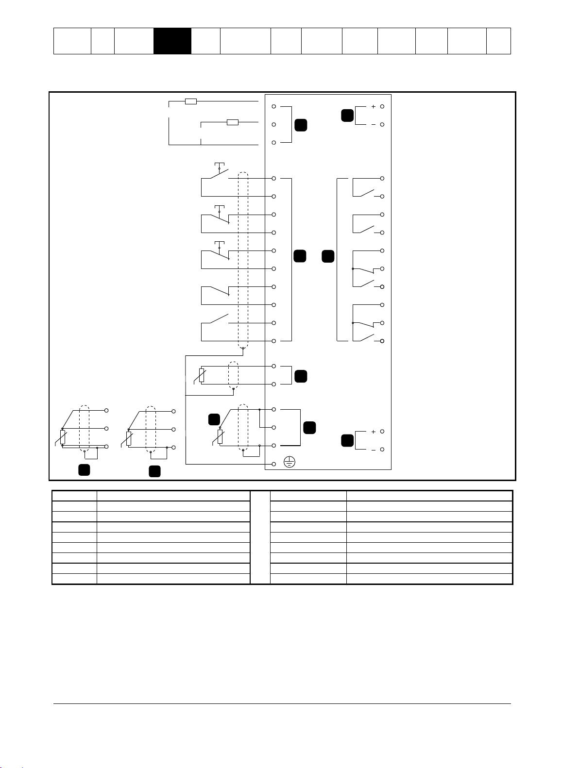
4.2 Control connections
08347.A
5
4
3
2
1
RLC3
COM3
COM1
RLO1
+24V
0V
RLO2
COM2
RLO3
AO1
0V
COM4
RLC4
RLO4
TH2
TH1
DI2
+24V
DI3
+24V
DI4
+24V
+24V
+24V
DI5
PT4
PT5
PT3
CSR
CSL
CSH
DI1
+10%
-15%
+10%
-15%
A
PT4
PT5
PT3
C
PT4
PT5
PT3
BB
E
7
6
220-440 VAC
110-210 VAC
1
Control voltage
DI1, +24V
Start 2 Remote control inputs
DI2, +24V
Stop
3
Motor thermistor input
DI3, +24V
Reset
4A
RTD/PT100 input - 2-wire
DI4, +24V
Programmable input A
4B
RTD/PT100 input - 3-wire
DI5, +24V
Programmable input B
4C
RTD/PT100 input - 4-wire
COM1, RLO1
Relay output A
5
24 Vdc output
COM2, RLO2
Run relay output
6
Relay outputs
COM3, RLC3, RLO3
Relay output B
7
Analog output
COM4, RLC4, RLO4
Relay output C
Figure 4-6 Digistart IS electrical schematic
The Digistart IS can be commanded to emergency stop the motor, ignoring the soft stop mode set in Pr 2H.
When the circuit across DI4, +24V is opened, the soft starter allows the motor to coast to stop.
To use the emergency stop function, set Pr 3A to 'Emergency Stop' (this is the default setting).
If emergency stop is not required, change the setting of Pr 3A or connect a link across DI4, +24V.
For keypad control, the soft starter requires:
control supply connections (terminals CSH, CSL, CSR depending on the control voltage)
programmable input A (DI4, +24V) must be closed or Pr 3A Input A Function must be changed from Emergency Stop
Digistart IS User Guide 21
Issue: 4 www.controltechniques.com

Safety
Information
Rating
Data
Mechanical
Installation
Electrical
Installation
Keypad
and
Status
Quick Start
Commissioning
Operation
Programming
Diagnostics
Application
Examples
Technical
Data
Maintenance
Options
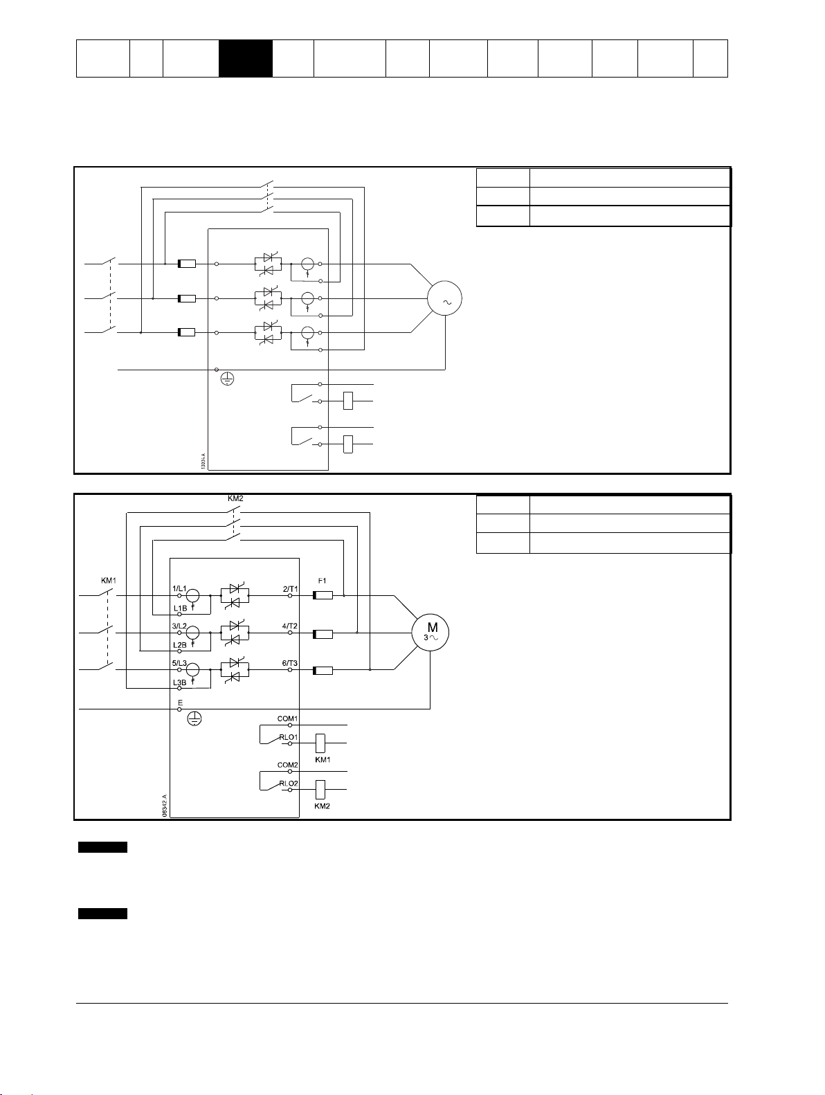
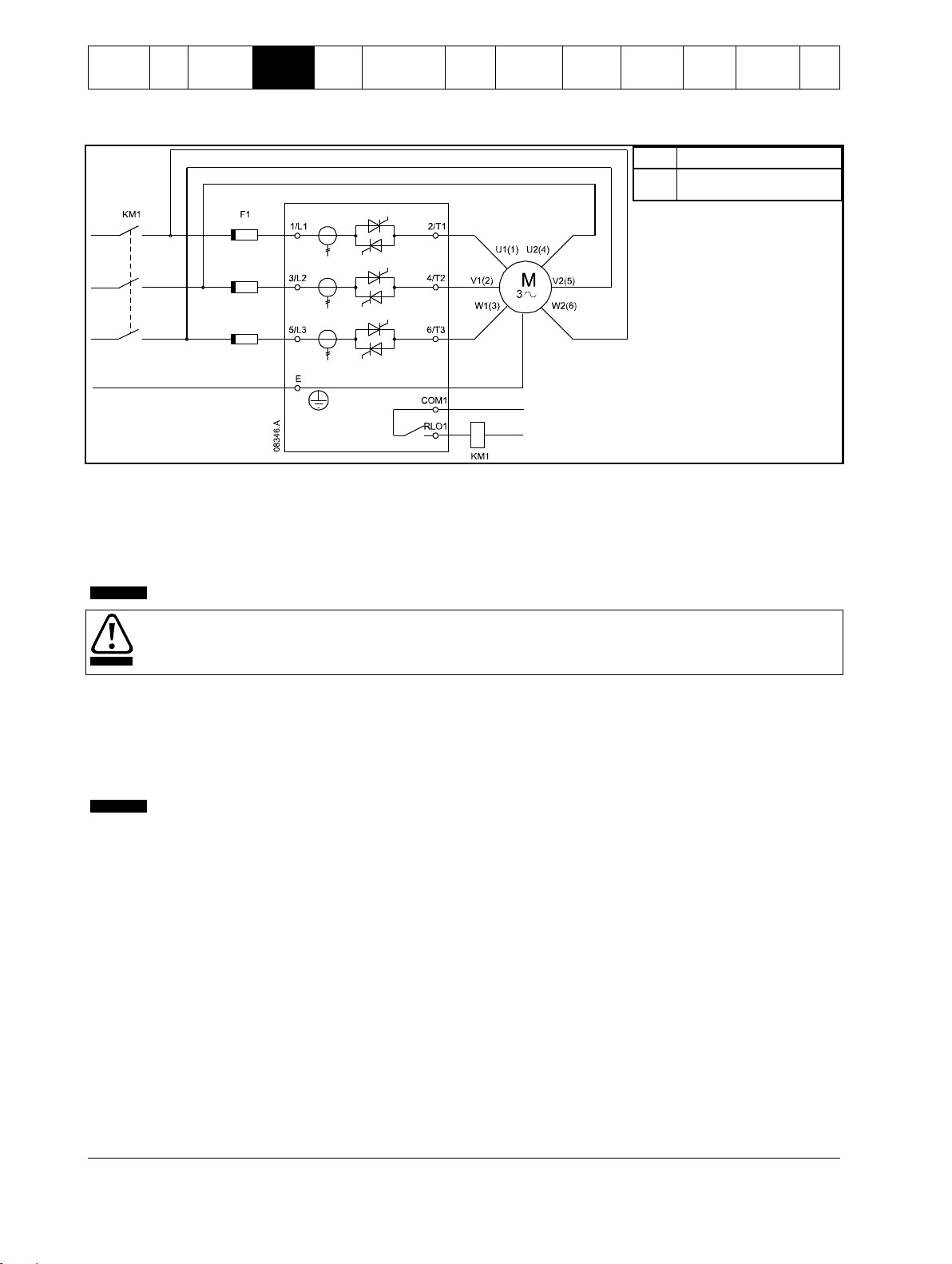
NOTE
For personnel safety, the power terminals on models up to IS1x0105B are protected by snap-off tabs. When using large
cables, it may be necessary to break off these tabs.
Models which are internally bypassed do not require an external bypass contactor.
6/T3
2/T1
5/L3
3/L2
1/L1
COM1
RLO1
4/T2
E
KM1
KM1 F1
M
3
08341.A
KM1
Main contactor (optional)
F1
Semiconductor fuses (optional)
NOTE
Main contactor is the default setting for Pr 4A Relay A Action (COM1, RLO1).
4.3 Power connections
4.3.1 Motor connection
Digistart IS soft starters can be connected to the motor in-line or inside delta (also called three-wire and six-wire connection). When
connecting in inside delta, enter the motor full load current (FLC) for Pr 1A. The Digistart IS will automatically detect whether the
motor is connected in-line or inside delta and will calculate the correct inside delta current level.
Internally bypassed models:
IS1x0023B, IS1x0043B, IS1x0053B, IS1x0076B, IS1x0097B, IS1x0105B, IS2x0145B, IS2x0170B, IS2x0200B, IS2x0220B,
IS3x0255B, IS4x0350B, IS4x0425B, IS4x0500B, IS4x0700B, IS4x0820B, IS4x0920B, IS4x1000B
Non-bypassed models:
IS3x0255N, IS4x0360N, IS4x0430N, IS4x0650N, IS4x0790N, IS4x0930N, IS561200N, IS561410N, IS561600N
4.3.2 In-line installation
In-line installation, internally bypassed
Figure 4-7 Power connections - in-line installation, internally bypassed
22 Digistart IS User Guide
www.controltechniques.com Issue: 4
Safety
Information
Rating
Data
Mechanical
Installation
Electrical
Installation
Keypad
and
Status
Quick Start
Commissioning
Operation
Programming
Diagnostics
Application
Examples
Technical
Data
Maintenance
Options
M
3
F1
6/ T3
2/ T1
5/L3
3/L2
1/ L1
COM1
RLO1
4/ T2
E
KM1
KM1
T1B
T2B
T3B
KM2
RLO2
COM2
KM2
KM1
Main contactor (optional)
KM2
Bypass contactor (external)
F1
Semiconductor fuses (optional)
KM1
Main contactor (optional)
KM2
Bypass contactor (external)
F1
Semiconductor fuses (optional)
NOTE
The bypass terminals on IS3x0255N are T1B, T2B, T3B. The bypass terminals on IS4x0360N to IS561600N are L1B,
L2B, L3B.
The fuses can be installed on the input side if required.
NOTE
Main contactor is the default setting for Pr 4A Relay A Action (COM1, RLO1). Output relay COM2, RLO2 is dedicated to
Run output operation and is ideal for managing an external bypass contactor.
In-line installation, externally bypassed
Non-bypassed models have dedicated bypass terminals, which allow the Digistart IS to continue providing protection and monitoring
functions even when bypassed via an external bypass contactor. The bypass contactor must be connected to the bypass terminals
and controlled by the soft starter's run output (terminals COM2, RLO2).
Figure 4-8 Power connections - in-line installation, externally bypassed (IS3x0255N)
Figure 4-9 Power connections - in-line installation, externally bypassed (IS4x0360N to IS561600N)
Digistart IS User Guide 23
Issue: 4 www.controltechniques.com

Safety
Information
Rating
Data
Mechanical
Installation
Electrical
Installation
Keypad
and
Status
Quick Start
Commissioning
Operation
Programming
Diagnostics
Application
Examples
Technical
Data
Maintenance
Options
KM1
Main contactor (optional)
F1
Semiconductor fuses (optional)
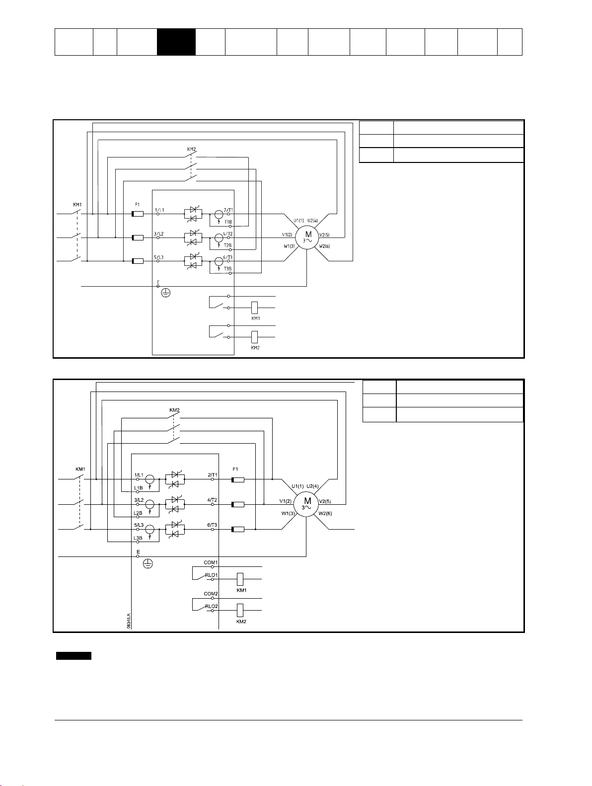
CAUTION
When connecting the Digistart IS in inside delta configuration, always install a main contactor or shunt trip circuit
breaker.
NOTE
When connecting in inside delta, enter the motor full load current (FLC) for Pr 1A. The Digistart IS will automatically
detect whether the motor is connected in-line or inside delta and will calculate the correct inside delta current level.
08344.A
M
3
6/T3
2/T1
COM1
RLO1
4/T2
KM1
U1(1) U2(4)
V1(2)
V2(5)
W1(3) W2(6)
5/L3
3/L2
1/L1
E
KM1 F1
KM1
Main contactor
F1
Semiconductor fuses
(optional)
In-line installation, non-bypassed
Figure 4-10 Power connections - in-line installation, non-bypassed
4.3.3 Inside delta installation
Inside delta installation, internally bypassed
Figure 4-11 Power connections - inside delta installation, internally bypassed
24 Digistart IS User Guide
www.controltechniques.com Issue: 4
Safety
Information
Rating
Data
Mechanical
Installation
Electrical
Installation
Keypad
and
Status
Quick Start
Commissioning
Operation
Programming
Diagnostics
Application
Examples
Technical
Data
Maintenance
Options
13037.A
COM1
COM2
RLO2
RLO1
KM1
Main contactor
KM2
Bypass contactor (external)
F1
Semiconductor fuses (optional)
KM1
Main contactor
KM2
Bypass contactor (external)
F1
Semiconductor fuses (optional)
NOTE
The bypass terminals on IS3x0255N are T1B, T2B, T3B. The bypass terminals on IS4x0360N to IS561600N are L1B,
L2B, L3B.
The fuses can be installed on the input side if required.
Inside delta installation, externally bypassed
Non-bypassed models have dedicated bypass terminals, which allow the Digistart IS to continue providing protection and monitoring
functions even when bypassed via an external bypass contactor. The bypass contactor must be connected to the bypass terminals
and controlled by the soft starter's run output (terminals COM2, RLO2).
Figure 4-12 Power connections - inside delta installation, externally bypassed (IS3x0255N)
Figure 4-13 Power connections - inside delta installation, externally bypassed (IS4x0360N to IS561600N)
Digistart IS User Guide 25
Issue: 4 www.controltechniques.com
Safety
Information
Rating
Data
Mechanical
Installation
Electrical
Installation
Keypad
and
Status
Quick Start
Commissioning
Operation
Programming
Diagnostics
Application
Examples
Technical
Data
Maintenance
Options
KM1
Main contactor
F1
Semiconductor fuses
(optional)
NOTE
Fuses are not delivered with Digistart IS soft starters.
CAUTION
Adaptive Control controls the motor's speed profile, within the programmed time limit. This may result in a higher level
of current than traditional control methods.
NOTE
Fuse selection is based on a 400% FLC start for 20 seconds in conjunction with standard published starts per hour,
duty cycle, 40°C ambient temperature and up to 1000 m altitude. For installations operating outside these conditions,
consult your local supplier.
These fuse tables contain recommendations only. Always consult your local supplier to confirm the selection for your
particular application.
Inside delta installation, non-bypassed
Figure 4-14 Power connections - inside delta installation, non-bypassed
4.4 Fuse information
4.4.1 Power supply fuses
Semiconductor fuses can be used for Type 2 coordination (according to IEC 60947-4-2 standard) and to reduce the risk of damage
to SCRs from transient overload currents.
HRC fuses (such as Ferraz AJT fuses) can be used for Type 1 coordination according to IEC 60947-4-2 standard.
For applications using Adaptive Control to soft stop the motor with stop times greater than 30 seconds, motor branch protection
should be selected as follows:
standard HRC line fuses: minimum 150% motor full load current
motor rated line fuses: minimum rating 100/150% motor full load current
motor control circuit breaker minimum long time setting: 150% motor full load current,
motor control circuit breaker minimum short time setting: 400% motor full load current for 30 seconds
26 Digistart IS User Guide
www.controltechniques.com Issue: 4

Safety
Information
Rating
Data
Mechanical
Installation
Electrical
Installation
Keypad
and
Status
Quick Start
Commissioning
Operation
Programming
Diagnostics
Application
Examples
Technical
Data
Maintenance
Options
Table 4-2 Bussman fuses - square body (170M)
Model
SCR I2t (A2s)
Supply Voltage
(< 440 Vac)
Supply Voltage
(< 575 Vac)
Supply Voltage
(< 690 Vac)
IS1x0023B
1150
170M1314
170M1314
170M1314
IS1x0043B
8000
170M1316
170M1316
170M1316
IS1x0053B
15000
170M1318
170M1318
170M1318
IS1x0076B
15000
170M1319
170M1319
170M1318
IS1x0097B
51200
170M1321
170M1321
170M1319
IS1x0105B
125000
170M1321
170M1321
170M1321
IS2x0145B
125000
170M1321
170M1321
170M1321
IS2x0170B
320000
170M2621
170M2621
170M2621
IS2x0200B
320000
170M2621
170M2621
170M2621
IS2x0220B
320000
170M2621
170M2621
170M2621
IS3x0255B
320000
170M2621
170M2621
170M2621
IS4x0350B
202000
170M5011
170M5011
––
IS4x0425B
320000
170M6011
––
––
IS4x0500B
320000
170M6008*
––
––
IS4x0700B
781000
170M5015
170M5015
––
IS4x0820B
1200000
170M5017
170M6015
––
IS4x0920B
2530000
170M6017
170M6017
––
IS4x1000B
2530000
170M6018
170M6013*
––
IS3x0255N
320000
170M2621
170M2621
170M2621
IS4x0360N
320000
170M6010
170M6010
170M6010
IS4x0430N
320000
170M6011
170M6011
––
IS4x0650N
1200000
170M6015
170M6015
170M6014
IS4x0790N
2530000
170M6017
170M6017
170M6016
IS4x0930N
4500000
170M6019
170M6019
170M6019
IS561200N
4500000
170M6021
––
––
IS561410N
6480000
––
––
––
IS561600N
12500000
170M6019*
––
––
Model
SCR I2t (A2s)
Supply Voltage
(< 440 Vac)
Supply Voltage
(< 575 Vac)
Supply Voltage
(< 690 Vac)
IS1x0023B
1150
63FE
63FE
63FE
IS1x0043B
8000
120FEE
120FEE
120FEE
IS1x0053B
15000
200FEE
200FEE
200FEE
IS1x0076B
15000
200FEE
200FEE
200FEE
IS1x0097B
51200
200FEE
200FEE
200FEE
IS1x0105B
125000
280FM
280FM
280FM
IS2x0145B
125000
280FM
280FM
280FM
IS2x0170B
320000
450FMM
450FMM
450FMM
IS2x0200B
320000
450FMM
450FMM
450FMM
IS2x0220B
320000
450FMM
450FMM
450FMM
IS3x0255B
320000
450FMM
450FMM
450FMM
IS4x0350B
202000
315FM*
––
––
IS4x0425B
320000
400FMM*
––
––
IS4x0500B
320000
450FMM*
––
––
IS4x0700B
781000
630FMM*
––
––
IS4x0820B
1200000
––
––
––
IS4x0920B
2530000
––
––
––
IS4x1000B
2530000
––
––
––
IS3x0255N
320000
450FMM
450FMM
450FMM
IS4x0360N
320000
––
––
––
IS4x0430N
320000
––
––
––
IS4x0650N
1200000
630FMM*
630FMM*
––
IS4x0790N
2530000
––
––
––
IS4x0930N
4500000
––
––
––
IS561200N
4500000
––
––
––
* Two parallel connected fuses required per phase.
Table 4-3 Bussman fuses - British style (BS88)
Digistart IS User Guide 27
Issue: 4 www.controltechniques.com
 Loading...