


SERVICE MANUAL
WASHING
|
P6 |
P3.0 |
|
|
|
|
|
|
|
|
|
|
|
|
Front-Loading Washing |
|
|
|
|
ELECTROLUX HOME PRODUCTS |
Publication |
Machines |
|
with electronic control |
|||
Customer Care - EMEA |
number |
system |
|
Training and Operations Support |
|
|
|
Technical Support |
|
|
EWX13611 |
|
|
|
|
|
599 77 39-16 |
|
|
|
|
EWX11831 |
|
|
EN |
||
|
|
||
|
|
|
Technical and functional |
|
|
|
characteristics |
Edition: 01/2014 - Rev. 00 |
|
|
|
|
|
|
PILOT 2 |
|
|
|
Styling |
|
|
|
P6 - P3.0 |
|
|
|
P49 |
Downloaded from www.Manualslib.com manuals search engine
Technical Support - MDM |
2/104 |
599 77 39-16 Rev. 00 |
Downloaded from www.Manualslib.com manuals search engine
INDEX
1 PURPOSE OF THIS MANUAL .................................................................................................................. |
|
6 |
||||
|
1.1 |
Low consumption mode...................................................................................................................... |
|
6 |
||
|
1.1.1 |
P6 P3.0 with universal motor (EWX13611)................................................................................... |
6 |
|||
|
1.1.2 |
P6 P3.0 with three-phase motor and Inverter (EWX11831) .......................................................... |
7 |
|||
2 |
WARNINGS |
.............................................................................................................................................. |
|
8 |
||
3 |
Styling P6.................................................................................................................................................. |
|
|
9 |
||
|
3.1 |
EWX13611 .....................................................................................................General characteristics |
|
9 |
||
|
3.2 |
EWX11831 ...................................................................................................General characteristics |
|
10 |
||
|
3.3 |
Control ....................................................................................................................................panel |
|
11 |
||
|
3.3.1 |
Display ............................................................................................................................board |
|
11 |
||
|
3.3.2 |
Control ........................................................................................................panel configuration |
|
12 |
||
|
|
3.3.2.1 .................................................................................................... |
Programme configuration |
|
12 |
|
|
|
3.3.2.2 .................................................................................................................. |
Sensors – LEDs |
|
12 |
|
|
|
3.3.2.3 .................................................................................................. |
Buttons – Sensors – LEDs |
|
13 |
|
|
|
3.3.2.4 ................................................................................................................................ |
Buzzer |
|
16 |
|
4 |
STYLING P3.0......................................................................................................................................... |
|
17 |
|||
|
4.1 |
EWX13611 ...................................................................................................General characteristics |
|
17 |
||
|
4.2 |
EWX11831 ...................................................................................................General characteristics |
|
18 |
||
|
4.3 |
Control ....................................................................................................................................panel |
|
19 |
||
|
4.3.1 |
Display ............................................................................................................................board |
|
19 |
||
|
4.3.2 |
Control ........................................................................................................panel configuration |
|
20 |
||
|
|
4.3.2.1 .................................................................................................... |
Programme configuration |
|
20 |
|
|
|
4.3.2.2 .................................................................................................. |
Buttons – Sensors – LEDs |
|
20 |
|
|
|
4.3.2.3 ............................................................................................................................... |
Display |
|
21 |
|
|
|
4.3.2.4 ................................................................................................................................ |
Buzzer |
|
21 |
|
5 |
DEMO MODE.......................................................................................................................................... |
|
22 |
|||
|
5.1 |
Accessing .......................................................................the DEMO setting for P6 and P3.0 stylings |
22 |
|||
|
5.2 |
Exiting DEMO .........................................................................................................................mode |
|
22 |
||
6 |
DIAGNOSTICS ........................................................................................................................SYSTEM |
|
23 |
|||
|
6.1 |
Accessing ...........................................................................the diagnostics for P6 and P3.0 stylings |
23 |
|||
|
6.2 |
Quitting ........................................................................................................the diagnostics system |
|
23 |
||
|
6.3 |
Phases ..........................................................................................................of the diagnostics test |
|
24 |
||
7 |
ALARMS ................................................................................................................................................. |
|
|
26 |
||
|
7.1 |
Displaying .....................................................................................................................user alarms |
|
26 |
||
|
7.1.1 |
Styling ..................................................................................................................................P6 |
|
26 |
||
|
7.1.2 |
Styling ...............................................................................................................................P3.0 |
|
27 |
||
|
7.2 |
Alarm reading/display ....................................................................................................................... |
|
28 |
||
|
7.2.1 |
Displaying ........................................................................................................the alarm (P3.0) |
|
28 |
||
|
7.2.2 |
Displaying ...........................................................................................................the alarm (P6) |
|
28 |
||
|
7.2.3 |
Example ...........................................................................................................of alarm display |
|
28 |
||
|
7.2.4 Behaviour .......................................................................of the alarms during diagnostic testing |
29 |
||||
|
7.2.5 |
Rapid .............................................................................................................reading of alarms |
|
30 |
||
|
7.2.6 |
Deleting ...............................................................................................................the last alarm |
|
30 |
||
8 OPERATING ...................................................................................TIME COUNTER (styling P3.0 only) |
31 |
|||||
|
8.1 |
Reading ...............................................................................................................the operating time |
|
31 |
||
|
8.2 |
Display ...........................................................................................................of total operating time |
|
31 |
||
9 |
OPTIONS................................................................................................................................................ |
|
|
32 |
||
|
9.1 |
Compatibility ..........................................................................................................between options |
|
32 |
||
|
9.2 |
Description .......................................................................................................................of options |
|
33 |
||
10 |
TECHNICAL .......................................................................................................CHARACTERISTICS |
|
34 |
|||
|
10.1 |
Construction ...................................................................................characteristics (universal motor) |
34 |
|||
|
10.2 |
Construction .................................................................characteristics (three-phase motor, Inverter) |
35 |
|||
|
10.3 |
Detergent .........................................................................................................................dispenser |
|
36 |
||
|
10.4 |
Detergent ..............................................................................................................................drawer |
|
37 |
||
|
10.5 |
Washing ....................................................................................................................................unit |
|
38 |
||
|
10.6 |
Water circuit ..................................................................................................................................... |
|
39 |
||
|
10.6.1 |
OKO/IDB ....................................................................................................version drain circuit |
|
39 |
||
|
10.7 |
Electronic ..............................................................................................................................control |
|
40 |
||
|
10.7.1 |
Programming/Updating ............................................................................the main circuit board |
40 |
|||
|
10.7.2 Electrical .............................................................................characteristics with universal motor |
41 |
||||
|
10.7.3 Electrical ....................................................characteristics with three-phase motor and Inverter |
41 |
||||
11 |
ELECTRICAL .............................................................................................................COMPONENTS |
|
42 |
|||
|
11.1 |
Noise filter ........................................................................................................................................ |
|
42 |
||
|
11.1.1 |
General ..............................................................................................................characteristics |
|
42 |
||
Technical Support - MDM |
3/104 |
599 77 39-16 Rev. 00 |
||||
Downloaded from www.Manualslib.com manuals search engine
11.2 |
Display board ................................................................................................................................... |
|
42 |
||
11.3 |
Drainage pump................................................................................................................................. |
|
43 |
||
11.3.1 |
General characteristics .............................................................................................................. |
|
43 |
||
11.4 |
Heating element ............................................................................................................................... |
|
44 |
||
11.4.1 |
General characteristics .............................................................................................................. |
|
44 |
||
11.5 |
Temperature probe........................................................................................................................... |
|
45 |
||
11.5.1 |
General characteristics .............................................................................................................. |
|
45 |
||
11.6 |
Analogue pressure switch................................................................................................................. |
|
46 |
||
11.6.1 |
General characteristics .............................................................................................................. |
|
46 |
||
11.7 |
Door safety interlock PTO (Pull To Open) ......................................................................................... |
|
47 |
||
11.7.1 |
General characteristics .............................................................................................................. |
|
47 |
||
11.7.2 |
Operating principle .................................................................................................................... |
|
47 |
||
|
11.7.2.1 |
Mechanical operation.......................................................................................................... |
|
48 |
|
11.7.3 |
Manual opening of the appliance door........................................................................................ |
|
49 |
||
11.8 |
Universal motor ................................................................................................................................ |
|
50 |
||
11.8.1 |
General characteristics .............................................................................................................. |
|
50 |
||
11.8.2 |
Operating principle .................................................................................................................... |
|
50 |
||
|
11.8.2.1 |
Motor speed control ............................................................................................................ |
|
50 |
|
|
11.8.2.2 Direction of rotation of the motor ......................................................................................... |
|
51 |
||
|
11.8.2.3 |
Tachometric generator........................................................................................................ |
|
51 |
|
11.8.3 |
Power supply to motor ............................................................................................................... |
|
52 |
||
11.9 |
Three-phase asynchronous motor – Inverter |
..................................................................................... |
53 |
||
11.9.1 |
General characteristics .............................................................................................................. |
|
53 |
||
11.9.2 |
Power supply to motor ............................................................................................................... |
|
53 |
||
11.10 Inverter............................................................................................................................................. |
|
|
54 |
||
11.10.1 |
General characteristics .............................................................................................................. |
|
54 |
||
11.11 Anti-foam control system .................................................................................................................. |
|
55 |
|||
11.12 Solenoid valves ................................................................................................................................ |
|
56 |
|||
11.12.1 |
General characteristics .............................................................................................................. |
|
56 |
||
11.12.2 |
Operating principle .................................................................................................................... |
|
56 |
||
11.12.3 |
Mechanical jamming of the solenoid valve ................................................................................. |
56 |
|||
11.12.4 |
Low water pressure ................................................................................................................... |
|
56 |
||
12 |
ALARM SUMMARY TABLE ................................................................................................................. |
|
57 |
||
13 |
DIAGRAMS.......................................................................................................................................... |
|
61 |
||
13.1 |
Operating Circuit Diagram EWX13611 (with universal motor)............................................................ |
61 |
|||
13.2 |
Key to operating circuit diagram EWX13611 (with universal motor) ................................................... |
62 |
|||
13.3 |
Operating Circuit Diagram EWX11831 (with three-phase motor) ....................................................... |
63 |
|||
13.4 |
Key to operating circuit diagram EWX11831 (with three-phase motor) .............................................. |
64 |
|||
14 |
ACCESSIBILITY (appliances with universal motor) .............................................................................. |
65 |
|||
14.1 |
Worktop............................................................................................................................................ |
|
|
65 |
|
14.2 |
From the worktop, you can access.................................................................................................... |
|
65 |
||
14.2.1 |
Main board ................................................................................................................................ |
|
65 |
||
14.2.2 |
Solenoid valve........................................................................................................................... |
|
68 |
||
14.2.3 |
Display board assembly............................................................................................................. |
|
68 |
||
14.2.4 |
Control panel............................................................................................................................. |
|
70 |
||
14.2.5 |
Analogue pressure switch.......................................................................................................... |
|
73 |
||
14.2.6 |
Detergent dispenser .................................................................................................................. |
|
74 |
||
14.2.7 |
Upper counterweight.................................................................................................................. |
|
75 |
||
14.3 |
Accessing the front part .................................................................................................................... |
|
76 |
||
14.3.1 |
Door hinge – Door ..................................................................................................................... |
|
76 |
||
14.3.2 |
Door safety interlock.................................................................................................................. |
|
76 |
||
14.3.3 |
Blade......................................................................................................................................... |
|
79 |
||
14.3.4 |
Front panel ................................................................................................................................ |
|
81 |
||
14.4 |
From the front panel, you can access ............................................................................................... |
|
82 |
||
14.4.1 |
Front counterweight................................................................................................................... |
|
82 |
||
14.4.2 |
Bellow seal ................................................................................................................................ |
|
82 |
||
14.4.3 |
Welded tub assembly ................................................................................................................ |
|
82 |
||
14.4.4 |
Tub suspension springs............................................................................................................. |
|
83 |
||
14.5 |
Accessing the rear part..................................................................................................................... |
|
84 |
||
14.5.1 |
Back panel ................................................................................................................................ |
|
84 |
||
14.6 |
From the back panel, you can access ............................................................................................... |
|
84 |
||
14.6.1 |
Belt............................................................................................................................................ |
|
|
84 |
|
14.6.2 |
Plastic pulley (Ø 273 mm).......................................................................................................... |
|
85 |
||
14.6.3 |
Motor........................................................................................................................................ |
|
85 |
||
14.6.4 |
Heating...................................................................................................................................... |
|
85 |
||
14.7 |
From the base of the appliance, you can access............................................................................... |
86 |
|||
Technical Support - MDM |
4/104 |
599 77 39-16 Rev. 00 |
|||
Downloaded from www.Manualslib.com manuals search engine
14.7.1 |
Drain water circuit...................................................................................................................... |
86 |
||
|
14.7.1.1 |
Drainage pump................................................................................................................... |
86 |
|
|
14.7.1.2 |
Drain filter........................................................................................................................... |
87 |
|
|
14.7.1.3 IDB (Integrated Drain Body)................................................................................................ |
87 |
||
14.7.2 |
Pressure chamber ..................................................................................................................... |
89 |
||
14.7.3 |
Shock absorbers........................................................................................................................ |
91 |
||
14.7.4 |
Shock absorber pin.................................................................................................................... |
91 |
||
14.7.5 |
Main drain pipe.......................................................................................................................... |
92 |
||
15 |
ACCESSIBILITY (appliances with INVERTER motor control) ............................................................... |
94 |
||
15.1 |
Worktop............................................................................................................................................ |
|
94 |
|
15.2 From the worktop, you can access.................................................................................................... |
94 |
|||
15.2.1 |
Main board ................................................................................................................................ |
94 |
||
15.2.2 |
Solenoid valve........................................................................................................................... |
95 |
||
15.2.3 |
Display board assembly............................................................................................................. |
95 |
||
15.2.4 |
Control panel............................................................................................................................. |
96 |
||
15.2.5 |
Analogue pressure switch.......................................................................................................... |
96 |
||
15.2.6 |
Detergent dispenser .................................................................................................................. |
96 |
||
15.2.7 |
Upper counterweight.................................................................................................................. |
96 |
||
15.3 |
Accessing the front part .................................................................................................................... |
96 |
||
15.3.1 |
Door hinge - Door...................................................................................................................... |
96 |
||
15.3.2 |
Door safety interlock.................................................................................................................. |
96 |
||
15.3.3 |
Blade......................................................................................................................................... |
96 |
||
15.3.4 |
Front panel ................................................................................................................................ |
96 |
||
15.4 From the front panel, you can access ............................................................................................... |
97 |
|||
15.4.1 |
Front counterweight................................................................................................................... |
97 |
||
15.4.2 |
Bellow seal ................................................................................................................................ |
97 |
||
15.4.3 |
Welded tub assembly ................................................................................................................ |
97 |
||
15.4.4 |
Tub suspension springs............................................................................................................. |
97 |
||
15.5 Accessing the rear part..................................................................................................................... |
97 |
|||
15.5.1 |
Back panel ................................................................................................................................ |
97 |
||
15.6 From the back panel, you can access ............................................................................................... |
97 |
|||
15.6.1 |
Belt............................................................................................................................................ |
|
97 |
|
15.6.2 Plastic pulley (Ø 273 mm).......................................................................................................... |
98 |
|||
15.6.3 |
Motor......................................................................................................................................... |
98 |
||
15.6.4 |
Heating...................................................................................................................................... |
98 |
||
15.6.5 |
UIMC......................................................................................................................................... |
98 |
||
15.6.6 |
Drainage pump........................................................................................................................ |
100 |
||
15.6.7 |
Drain filter................................................................................................................................ |
101 |
||
15.7 From the base of the appliance, you can access.............................................................................. |
102 |
|||
15.7.1 |
Drain water circuit.................................................................................................................... |
102 |
||
|
15.7.1.1 |
Drainage pump................................................................................................................. |
102 |
|
|
15.7.1.2 |
Drainage filter ................................................................................................................... |
102 |
|
|
15.7.1.3 IDB (Integrated Drain Body).............................................................................................. |
103 |
||
15.7.2 |
Pressure chamber ................................................................................................................... |
103 |
||
15.7.3 |
Shock absorbers...................................................................................................................... |
103 |
||
15.7.4 |
Main drain pipe........................................................................................................................ |
103 |
||
Technical Support - MDM |
5/104 |
599 77 39-16 Rev. 00 |
Downloaded from www.Manualslib.com manuals search engine
1 PURPOSE OF THIS MANUAL
The purpose of this manual is to provide service engineers who are already familiar with the repair procedures for traditional washing machines with information regarding washing machines fitted with the EWX13611 (P6-P3.0) and EWX11831 (P6-P3.0) electronic control systems.
Previous platforms (electronic/mechanical) used a safety pressure switch that checked the minimum water level in the tub, below which the supply to the heating element was interrupted.
The current electronic appliances manufactured use a heating element with thermal fuses (inside its branches) as safety, which interrupt if the water level drops below the minimum level permitted.
The incorporated NTC probe contacts have a 2.5 mm pitch.
The manual deals with the following topics:
General characteristics
Control panel and compatibility between washing programmes and options
Settings: Demo, Diagnostics
Alarms
Technical and functional characteristics
Access
1.1 Low consumption mode
In order to reduce electricity waste when the cycle is not running, the appliances on this platform are designed to enter consumption reduction mode:
1.1.1P6 P3.0 with universal motor (EWX13611)
“Stand-Off” mode
When the appliance is switched off at the ON/OFF button, it is in the “Stand-Off” or “virtual” off status. The LEDs and the LCD screen are turned off and the buttons are disabled, although the main circuit board and certain electrical components are electrically powered.
You have to unplug the appliance to cut off the power supply
“Auto-off” mode
If, after 5 minutes, during the programme selecting phase or after the end of the cycle, the appliance receives no further instructions, it is automatically turned off (for energy savings in conformity with the standards on energy consumption).
All the settings are stored so that when the appliance is turned back on, the programme is ready or if the autooff mode was triggered after the end of the cycle, the user can see that the cycle ended normally, and can restart it if necessary.
You have to unplug the appliance to cut off the power supply
If an alarm goes off when a wash programme is running, the automatic turn off is disabled showing the alarm.
Technical Support - MDM |
6/104 |
599 77 39-16 Rev. 00 |
Downloaded from www.Manualslib.com manuals search engine
1.1.2P6 P3.0 with three-phase motor and Inverter (EWX11831)
Some appliances are fitted with a circuit (in the main circuit board) called Zero Watt (0 Watt with an actual consumption ~50 mW) which cuts off the power supply to the appliance:
a.When you press the ON/OFF button to turn off the appliance, the Zero Watt circuit is triggered and cuts off the supply voltage after a few seconds, just long enough to secure the washing machine (motor off, door locked, etc…), the cycle and any options selected are reset, so that the next time the appliance is turned on, it is ready to perform the programme.
(To open the door, you will have to wait one or two minutes for the door safety lock to be released.)
b.If, after 5 minutes, during the programme selecting phase or after the end of the cycle, the appliance receives no further instructions, it is automatically turned off and the Zero Watt circuit which cuts off the supply voltage is triggered (for energy savings in conformity with the standards on energy consumption). All the settings are stored so that when the appliance is turned back on, the programme is ready or if the auto-off mode was triggered after the end of the cycle, the user can see that the cycle ended normally, and can restart it if necessary.
If an alarm goes off when a wash programme is running, the automatic turn off is disabled showing the alarm.
The appliances which are not equipped with the Zero Watt (0 Watt) circuit in: “Stand-Off” or “Auto-off” mode, see para. 1.1.1.
Technical Support - MDM |
7/104 |
599 77 39-16 Rev. 00 |
Downloaded from www.Manualslib.com manuals search engine

2 WARNINGS
Any work on electrical appliances must only be carried out by qualified personnel.
Before carrying out work on the appliance, use suitable instruments to check that the power supply system in the house is fully efficient. For example: refer to the indications provided/illustrated in the <<metratester>> course at the address (http://electrolux.edvantage.net) on the Electrolux Learning Gateway portal.
On completing operations, check that the appliance has been restored to the same state of safety as when it came off the assembly line.
If the circuit board has to be handled/replaced, use the ESD kit (Cod. 405 50 63-95/4) to avoid static electricity from damaging the circuit board, see S.B. No. 599 72 08-09 or consult the course <<Electrostatic charges>> at the address (http://electrolux.edvantage.net) on the Electrolux Learning Gateway portal.
This platform is not fitted with an ON/OFF switch. Before you access internal components, take the plug out of the socket to cut the power supply.
Make resistance measurements, rather than direct voltage and current measurements.
Warning the sensors located in the display board could be at a potential of 220 Volts.
When replacing the heating element, replace it with one that has the same characteristics (2 thermal fuses) in order not to compromise the safety of the appliance. NEVER remove/switch the NTC sensors between heating elements.
Always empty the appliance of all the water before laying it on its side (see the relevant paragraph).
Never place the appliance on its right side (electronic control system side):
some of the water in the detergent dispenser could leak onto the electrical/electronic components and cause these to burn.
When replacing components, please refer to the code shown in the list of spare parts relating to the appliance.
Do not place any kind of container under the appliance to catch any drips of water.
Make sure you wear gloves, because parts of the cabinet are sharp.
Technical Support - MDM |
8/104 |
599 77 39-16 Rev. 00 |
Downloaded from www.Manualslib.com manuals search engine
3 Styling P6
3.1 EWX13611 General characteristics
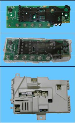
The electronic control system consists of two circuit boards.
In the event of problems with the touch sensors (difficulty selecting/adjusting them), clean and dry the display and do not wear gloves when setting the chosen programme.
The control/display board, which is inserted in a plastic container fixed to the control panel (the figure shows: the display board and the display board assembly).
Main board, positioned at the rear of the appliance. It powers the electrical components and receives commands from the display board.
No. buttons |
|
1 Maximum |
|
No. of touch-sensitive keys |
|
Maximum 6 (5 options + start/pause) |
|
No. LEDs |
|
Maximum 27 yellow + 1 red LED + Digit (made up of 22 LEDs) |
|
Power supply voltage |
|
220/240 V |
|
|
50/60 Hz (configurable) |
||
|
|||
Washing type |
|
Traditional with “Eco-IDB” |
|
Rinsing system |
|
Traditional with “Eco-IDB” |
|
Motor |
|
Collector, with tachometric generator (Universal) |
|
Spin speed |
|
1,000 1,400 rpm |
|
Anti-unbalancing system |
|
AGS |
|
Cold water fill |
|
1 solenoid valve with 1 inlet – 2 outlets |
|
Detergent dispenser |
|
2 compartments: wash, conditioners |
|
Control of water level in the tub |
|
Electronic/analogue pressure switch |
|
Door safety interlock |
|
Instant “Pull To Open” |
|
Heating element heat output |
|
1,750 W with thermal fuses incorporated |
|
Temperature check |
|
NTC probe incorporated in the heating element |
|
Buzzer |
|
Traditional incorporated in the PCB |
Technical Support - MDM |
9/104 |
599 77 39-16 Rev. 00 |
Downloaded from www.Manualslib.com manuals search engine

3.2 EWX11831 General characteristics
The electronic control system consists of three circuit boards.
In the event of problems with the touch sensors (difficulty selecting/adjusting them), clean and dry the display and do not wear gloves when setting the chosen programme.
The control/display board, which is inserted in a plastic container fixed to the control panel (the figure shows: the display board and the display board assembly).
The main circuit board is positioned at the rear of the appliance and powers the electrical components, receiving commands from the display board as well as communicating with the motor control board (Inverter UIMC).
Inverter UIMC
EWX11831 Main Board
No. of buttons |
|
Maximum 1 |
|
No. of touch-sensitive keys |
|
Maximum 6 (5 options + start/pause) |
|
No. LEDs |
|
Maximum 27 yellow + 1 red LED + Digit (made up of 22 LEDs) |
|
Power supply voltage |
|
220/240 V |
|
|
50/60 Hz (configurable) |
||
|
|||
Washing type |
|
Traditional with “Eco-IDB” |
|
Rinsing system |
|
Traditional with “Eco-IDB” |
|
Motor |
|
Two-pole asynchronous (three-phase) |
|
Spin speed |
|
1,000 1,600 rpm |
|
Anti-unbalancing system |
|
AGS |
|
Cold water fill |
|
1 solenoid valve with 1 inlet – 2 outlets |
|
Detergent dispenser |
|
2 compartments: wash, conditioners |
|
Control of water level in the tub |
|
Electronic/analogue pressure switch |
|
Door safety interlock |
|
Instant “Pull To Open” |
|
Heating element heat output |
|
1,750 W with thermal fuses incorporated |
|
Temperature check |
|
NTC probe incorporated in the heating element |
|
Buzzer |
|
Traditional incorporated in the PCB |
Technical Support - MDM |
10/104 |
599 77 39-16 Rev. 00 |
Downloaded from www.Manualslib.com manuals search engine
3.3 Control panel
Max. 1 Button
Max. 6 touch sensors
30 yellow LEDs + 1 red LED
3.3.1Display board
Display board assembly, exploded view
1Display board
2Light divider
Technical Support - MDM
Downloaded from www.Manualslib.com manuals search engine
1
2
11/104 |
599 77 39-16 Rev. 00 |

3.3.2Control panel configuration
|
L1 |
|
|
|
|
L25 |
|
|
|
|
|
L26 |
|
|
L2 |
L9 |
L14 |
L19 |
S7 |
L27 |
|
L3 |
L10 |
L15 |
L20 |
||
|
L4 |
|
L16 |
|
L28 L29L30 |
|
|
L5 |
L11 |
L21 |
|
|
|
|
L6 |
L12 |
L17 |
L22 |
|
|
|
L7 |
|
|
|||
|
L8 |
L13 |
L18 |
L23 |
|
L24 |
P1 |
S1 |
S2 |
S3 |
S4 |
S5 |
|
The washing programmes and the functions and the various touch sensors vary according to the model, since these are determined by the configuration of the appliance.
3.3.2.1Programme configuration
The table below lists the parameters that can be used to define the washing programmes.
Types of fabric |
Cotton/linen, Synthetic fabrics, Delicates, Wool, Hand-wash, |
|
Shoes, Jeans, Duvet, Silk. |
||
|
||
Special programmes |
Cotton/linen + pre-wash, Soak, Miniprogramme, Easy-Iron, |
|
Conditioner, Rinse, Drain, Spin, Economy. |
||
|
||
Temperature |
Normal, Minimum, Maximum: the initial temperature is the one |
|
proposed for the washing programme. |
||
|
||
Spin |
Normal, Minimum, Maximum. |
|
Options (Normal/Possible) |
Rinse Hold, Pre-wash, Extra rinse, Easy-Iron, Economy (energy |
|
label), Normal, Super quick, Reduced spin speed, No spin. |
||
|
||
Programme phases |
Pre-wash, Wash, Rinses, Spin, Delayed start. |
3.3.2.2Sensors – LEDs
The function of each touch sensor is defined via the configuration of the appliance (the data and images are for guidance only).
The touch sensors are positioned under the silk-screen printed symbols on the control panel (circled here in red).
A light touch on the centre of the symbol is enough to activate/deactivate the function linked to the sensor with the switching on/off of the relative Led confirming that the enabling/disabling has taken place.
At the same time as the enabling/disabling of options, the cycle duration time is updated via the digits (styling P3.0 only).
You need to keep your finger pressed down for a longer period of time with the Start/Pause sensor to confirm both the cycle’s start and pause, in order to avoid unwanted starts or accidental pauses.
Technical Support - MDM |
12/104 |
599 77 39-16 Rev. 00 |
Downloaded from www.Manualslib.com manuals search engine

Every time you touch a sensor, you need to lift your finger up by a centimetre and half a second needs to elapse before touching it again, otherwise the electronic system does not recognise that the sensor has been touched for a second time.
The sensors used for adjusting the: Temperature, Spin, delayed Start and Time Manager have a continued variation of values as long as your finger is in contact with the sensor.
3.3.2.3Buttons – Sensors – LEDs
Button no. 1: ON/OFF – ON
Press it to turn the appliance on, at the same time the buzzer will sound a tone (if enabled), the LEDs of the first four touch sensors (S1÷S4) will light up from the bottom up, then the LEDs relating to the following will stay on: the main programme, the recommended spin speed and temperature.
The operation of the ON/OFF depends on the configuration of the main circuit board. It can cut the appliance off from the electricity mains completely (0 Watt circuit) or set the appliance to low energy consumption mode (without 0 Watt circuit) in which case you will need to take the plug out of the socket to cut off the electricity supply completely.
Press the ON/OFF button to cancel the chosen programme. P1 To switch the appliance off, hold down the button for 1 second, at the same time the
buzzer will sound a tone (if enabled), all the LED will switch off, all the options selected and any programme that is running will be cancelled.
Sensor no. 1: PROGRAMMES
The programmes are associated with the second sensor, combined with eight LEDs (L1÷L8).
As soon as the appliance is switched on, the first LED at the top corresponding to the main programme lights up.
To the left of each LED, there is a description of the programme and each time the sensor is touched, the LED underneath it lights up, so the programme selection occurs from the top down; once the last programme has been reached, if you touch the sensor again, the selection returns to the top, i.e. the initial programme.
The selected programme is shown by the LED beside the description silk-screen printed on the control panel lighting up.
For a quicker selection, hold your finger down on the sensor for longer.
Sensor no. 2: TEMPERATURE
L1
L8
S1
The temperature is associated with the second sensor, combined with five LEDs (L9÷L13).
The initial temperature displayed is that set for the chosen programme.
By touching the sensor you can lower the temperature. Once this has been reached the selection starts again from the highest available one for the selected programme.
The selected temperature is shown by turning on the LEDs near the silk-screen printed value on the control panel.
The temperatures available are: 90 °C, 60 °C, 40 °C, 30 °C, cold cycle.
The initial temperature set for each programme is configurable;
For a quicker selection, hold your finger down on the sensor for longer.
L9
L13
S2
Technical Support - MDM |
13/104 |
599 77 39-16 Rev. 00 |
Downloaded from www.Manualslib.com manuals search engine

Sensor no. 3: SPIN SPEED (configurable)
The function of the third sensor is dedicated to the spin speed selection, combined with the five LEDs (L14÷L18) above; the related speed is silk-screen printed beside them on the control panel.
The initial spin speed is that set for the chosen programme.
Touch the sensor to reduce the spin speed, indicated by the LED near the silk-screen printed value on the control panel lighting up at the same time to confirm your selection. Once the lowest speed has been reached, you can, if you wish, select “Rinse hold” and the related LED beside the symbol silk-screen printed on the control panel lights up. The next selection will be the highest speed available for the selected programme.
For a quicker selection, hold your finger down on the sensor for longer.
The speeds that can be combined with the five LEDs are shown in the following table.
L14
L18
S3
Max spin |
800 |
1,000 |
1,000 |
1,200 |
1,200÷1,400 |
1,200÷1,400 |
1,400-1,600 |
1,400-1,600 |
1,400-1,600 |
|
speed (rpm) |
||||||||||
|
|
|
|
|
1,000 |
|
|
|
||
Intermediate |
600 |
800 |
800 |
800 |
1,000 |
1,200 |
1,200 |
1,200 |
||
Intermediate |
400 |
400 |
600 |
400 |
800 |
800 |
800 |
800 |
1,000 |
|
Intermediate |
0 |
0 |
400 |
0 |
0 |
400 |
0 |
400 |
800 |
|
Min. speed |
Rinse |
Rinse |
0 |
Rinse |
Rinse |
0 |
Rinse |
0 |
0 |
|
hold |
hold |
hold |
hold |
hold |
||||||
|
|
|
|
|
The recommended intermediate spin speeds are:
800 rpm for the following programmes: Lingerie, Duvet, Shirts, Sport, 14 min., Silk, etc… 1,000 rpm for the Easy-Iron option
1,200 rpm for synthetic fabrics, delicates, wool
If you select the “Rinse hold” option when the cycle ends, the related LED flashes to remind the end user to drain the water before opening the appliance door.
With the “Easy-Iron” option, the spin speed is reduced to 1000 rpm even if the spin speed selected is higher; if the option is deselected, the speed automatically returns to the chosen value.
Sensor no. 4: OPTIONS (configurable)
The function of the fourth sensor is dedicated to the choice of option to combine with the programme, combined with five LEDs (L19÷L23) above, beside which the name of the related option is silk-screen printed on the control panel.
Touch the sensor when no option has been enabled (all the LEDs are switched off) to light up the first LED relating to the most important option in the list.
Continue your selection to light up the subsequent LED (from the top down) and the previous one is switched off, all the way to the last option at the bottom. The next time you press the sensor all the LEDs will remain switched off.
You can only select one option per programme, as no combinations are possible. For a quicker selection, hold your finger down on the sensor for longer.
The following options can be combined with the first three LEDs (at the top):
Super Quick
Easy Iron
Intensive
Pre-wash
Daily
Half-load
Soak
L19
L23
S4
The two LEDs (at the bottom) are combined with:
Rinse Only – performs the last rinse cycle for the selected programme. If “Extra Rinse” is set, two or more rinse cycles are added (depending on the configuration).
Spin/Drain – performs the spin cycle for the selected programme, if the selected option is “No Spin” it only drains off the water.
Technical Support - MDM |
14/104 |
599 77 39-16 Rev. 00 |
Downloaded from www.Manualslib.com manuals search engine

Sensor no.5: START/PAUSE |
|
|
This sensor has the START/PAUSE function, used to start up a washing programme, |
|
|
after selecting the washing cycle and required options; it can also pause a cycle that |
|
|
has already started: to allow you to change selected option or open the door (if the |
L24 |
|
temperature conditions or water level allow for this). |
||
|
||
The cycle re-starts if you touch the sensor again. |
|
|
The (L24) LED combined with this sensor flashes slowly: in the selection phase, during |
|
|
the pause and at the end of a cycle with water in the tub. |
S5 |
|
It stays lit when a cycle is running and turns off when the cycle has ended and the door |
|
|
is unlocked. |
|
|
While other sensors when touched immediately change from selected to de-selected, |
|
|
in the case of this sensor, more time is needed to avoid unwanted cycle start ups |
|
|
or pauses. |
|
|
In the event of an incorrect selection by the end user, such as: an option that is not |
|
|
compatible with the selected programme or that has been made after the programme |
|
|
has commenced, this is indicated by three quick red flashes. The same LED is used to |
|
|
notify the user of any specific problems with the appliance. The buzzer does not play |
|
|
any particular tune. |
|
|
Sensor no.6:- DELAYED START (configurable) |
|
|
This sensor works as the DELAYED START and it is combined with the three |
L25 |
|
LEDs (L25÷L27) that surround it. |
||
Touch it in sequence to choose from one of the three delayed start options: 3 h- |
L26 |
|
6 h-9 h with the related LED coming on. |
L27 |
|
In order to reset the delay time, reach the maximum delay time and the next time |
||
the sensor is pressed the delay time is cancelled and no LED is lit up, or if the |
S6 |
delayed start has already been set, put the appliance on PAUSE and reset the time as described earlier.
Indicator LEDs
In addition to lighting up when their functions have been enabled, in combination with the red |
L28L29L30 |
|
|
LED of the START/PAUSE sensor, they notify the end user of any specific problems with the |
|
appliance that may be solved without having to call for technical assistance (see page 26). |
|
Padlock: |
|
When the related LED (L28) is lit, it indicates that all the sensors are disabled to prevent |
|
children from altering, starting or pausing the cycle. |
|
When enabled, touch any sensor and the LED flashes three times to remind the end user |
|
that the appliance is locked. |
|
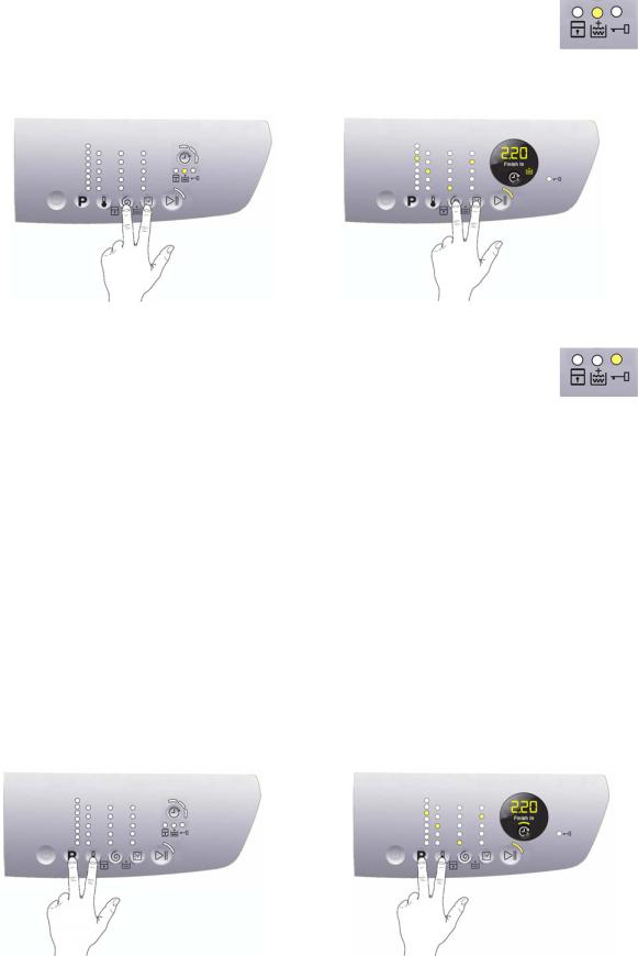
Use the combination of two sensors (touch for approximately 5 seconds) illustrated in the figure below to enable/disable this option.
|
|
P6 |
|
P3.0 |
|
|
|
|
|
|
|
Technical Support - MDM |
15/104 |
599 77 39-16 Rev. 00 |
|||
Downloaded from www.Manualslib.com manuals search engine
Extra Rinse:
When the related LED (L29) is lit up, this indicates that the option is enabled (it lights up during the washing and rinse cycles, and it remains switched off during the drain and spin cycle). The option remains enabled even after the appliance has been turned off (for subsequent programmes).
Use the combination of two sensors illustrated in the figure below to enable/disable this option.
P6 |
|
P3.0 |
|
|
|
Door lock:
When the related LED (L30) is lit up, the safety device prevents the door opening and switches off when the door can be opened.
Flashes when the device is about to unlock the door (with door interlock with PTC, which needs one/two minutes to open).
3.3.2.4Buzzer
This comprises a multi-tone buzzer and sounds in the following cases:
When the machine is turned on and off it emits two different tunes.
When a sensor is pressed it emits a short “Click”
When the cycle ends this is indicated by a special sequence of “three long beeps” repeated at intervals of 15” for a total of 2 minutes. The sequence can only be stopped by opening the door in appliances where the instant door safety device with micro-switch is fitted.
In the event of a malfunction in the machine this is indicated by a special sequence of “three short beeps” repeated 3 times at intervals of 15” for a total of 5 minutes.
All appliances are fitted with the buzzer, and leave the factory with the option enabled. To disable it use the combination of sensors.
The volume level is set in the factory and cannot be adjusted by the user.
When the buzzer is disabled (using the combination of sensors) it only emits the short “Click” and the sequence of “three short beeps” when an alarm is triggered.
During the programme selection phase, the buzzer can be enabled/disabled with a sensor combination (which may be silk-screen printed on the control panel or described in the instruction manual), but the alarm signalling remains enabled.
P6 |
|
P3.0 |
|
|
|
To enable it, touch the sensors simultaneously for 3 seconds. A short beep will confirm that it has been enabled, whereas two short beeps will confirm that it has been disabled.
Technical Support - MDM |
16/104 |
599 77 39-16 Rev. 00 |
Downloaded from www.Manualslib.com manuals search engine

4 STYLING P3.0
4.1 EWX13611 General characteristics
The electronic control system consists of two circuit boards.
In the event of problems with the touch sensors (difficulty selecting/adjusting them), clean and dry the display and do not wear gloves when setting the chosen programme.
The control/display board, which is inserted in a plastic container fixed to the control panel (the figure shows: the display board and the display board assembly).
Main board, positioned at the rear of the appliance. It powers the electrical components and receives commands from the display board.
No. of buttons |
|
1 Maximum |
|
No. of touch-sensitive keys |
|
Maximum 6 (5 options + start/pause) |
|
No. LEDs |
|
Maximum 24 yellow + 1 red LED + Digit (made up of 22 LEDs) |
|
Power supply voltage |
|
220/240 V |
|
|
50/60 Hz (configurable) |
||
|
|||
Washing type |
|
Traditional with “Eco-IDB” |
|
Rinsing system |
|
Traditional with “Eco-IDB” |
|
Motor |
|
Collector, with tachometric generator (Universal) |
|
Spin speed |
|
1,000 1,600 rpm |
|
Anti-unbalancing system |
|
AGS |
|
Cold water fill |
|
1 solenoid valve with 1 inlet – 2 outlets |
|
Detergent dispenser |
|
2 compartments: wash, conditioners |
|
Control of water level in the tub |
|
Electronic/analogue pressure switch |
|
Door safety interlock |
|
Instant “Pull To Open” |
|
Heating element heat output |
|
1,750 W with thermal fuses incorporated |
|
Temperature check |
|
NTC probe incorporated in the heating element |
|
Buzzer |
|
Traditional incorporated in the PCB |
Technical Support - MDM |
17/104 |
599 77 39-16 Rev. 00 |
Downloaded from www.Manualslib.com manuals search engine

4.2 EWX11831 General characteristics
The electronic control system consists of three circuit boards.
In the event of problems with the touch sensors (difficulty selecting/adjusting them), clean and dry the display and do not wear gloves when setting the chosen programme.
The control/display board, which is inserted in a plastic container fixed to the control panel (the figure shows: the display board and the display board assembly).
The main circuit board is positioned at the rear of the appliance and powers the electrical components, receiving commands from the display board as well as communicating with the motor control board (Inverter UIMC).
Inverter UIMC
No. of buttons |
|
1 Maximum |
|
No. of touch-sensitive keys |
|
Maximum 6 (5 options + start/pause) |
|
No. LEDs |
|
Maximum 24 yellow + 1 red LED + Digit (made up of 22 LEDs) |
|
Power supply voltage |
|
220/240 V |
|
|
50/60 Hz (configurable) |
||
|
|||
Washing type |
|
Traditional with “Eco-IDB” |
|
Rinsing system |
|
Traditional with “Eco-IDB” |
|
Motor |
|
Two-pole asynchronous (three-phase) |
|
Spin speed |
|
1,000 1,600 rpm |
|
Anti-unbalancing system |
|
AGS |
|
Cold water fill |
|
1 solenoid valve with 1 inlet – 2 outlets |
|
Detergent dispenser |
|
2 compartments: wash, conditioners |
|
Control of water level in the tub |
|
Electronic/analogue pressure switch |
|
Door safety interlock |
|
Instant “Pull To Open” |
|
Heating element heat output |
|
1,750 W with thermal fuses incorporated |
|
Temperature check |
|
NTC probe incorporated in the heating element |
|
Buzzer |
|
Traditional incorporated in the PCB |
Technical Support - MDM |
18/104 |
599 77 39-16 Rev. 00 |
Downloaded from www.Manualslib.com manuals search engine
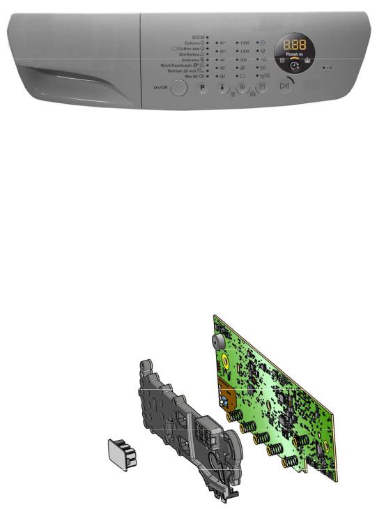
4.3 Control panel
Max. 1 Button Max. 6 sensors 25 LEDs
1 LCD
4.3.1Display board
Display board assembly, exploded view
1
1 |
Display board |
|
2 |
Light divider |
|
3 |
Light diffuser |
2 |
3
Technical Support - MDM |
19/104 |
599 77 39-16 Rev. 00 |
Downloaded from www.Manualslib.com manuals search engine
4.3.2Control panel configuration
L1 |
|
|
|
|
|
L2 |
L9 |
L14 |
L19 |
|
|
L3 |
L10 |
L15 |
L20 |
|
|
L4 |
|
|
|||
L5 |
L11 |
L16 |
L21 |
L25 L26 |
L27 |
L6 |
L12 |
L17 |
L22 |
||
L7 |
S6 |
L28 |
|||
L8 |
L13 |
L18 |
L23 |
||
|
|
|
|
L24 |
|
P1 S1 |
S2 |
S3 |
S4 |
S5 |
|
All the functions of button P1 and of sensors S1 to S5 are the same as those described for styling P6 (see page 12).
4.3.2.1Programme configuration (See page 12.)
4.3.2.2Buttons – Sensors – LEDs
All the functions: of button P1, of sensors S1 to S5 are the same as those described for styling P6 (see page 13).
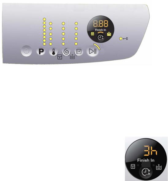
Sensor no.6: THE CYCLE FINISHES IN (Finish In)
This sensor allows the end user to programme in how many hours’ time the washing cycle will finish.
In detail, the cycle start can be delayed so as to have the cycle end at the desired time.
You can select from a minimum of 3 hours to a maximum of 20 hours.
The first time you press the sensor, the display indicates 3 hours and the related LED (26) lights up to indicate the option is enabled. The next time you press it, the time increases by 1 hour, up to a total of 10 hours. The increase is of 2 hours every time you press the button for the range between 10 and 20 hours.
If the display indicates 20 hours, the next time you press the sensor, “Finish In” will be disabled and the washing cycle time will be displayed and the LED (26) will switch off.
For a quicker selection, hold your finger down on the sensor for longer.
Setting an option after selecting “Finish In”
L26
S6
“Finish In” must be enabled after an option has been selected (if necessary) and before you start the cycle. If the end user, after setting “Finish In”, modifies the programme settings, “Finish In” will be disabled, the LED (26) will flash once and the display will once again indicate the washing cycle time.
“Finish In” after touching the START sensor
Once you have selected the programme and the option (if necessary) and set “Finish In”, the washing cycle starts when you touch the START sensor; the appliance door is locked and the countdown begins, and is indicated on the display at one-hour intervals until the start of the washing cycle. Once the “Finish In” time is up, the display indicates the amount of time necessary to perform the washing cycle, starting the countdown of the cycle with one-minute intervals, until the end of the cycle.
If the appliance is paused during the countdown of the “Finish In” option to change the option and including “Finish In”, the delay time is deleted and “Finish In” is disabled; touch the sensor and the display will indicate “error”.
Technical Support - MDM |
20/104 |
599 77 39-16 Rev. 00 |
Downloaded from www.Manualslib.com manuals search engine
4.3.2.3Display
Padlock
(See page 15.)
Extra Rinse
(See page 16.)
The following information also appears on the display:
Washing programme time
This appears after a washing programme has been selected. This time corresponds to the time required for the maximum wash load for each type of programme.
After the programme has started, the time decreases (and is updated) minute by minute.
When the time is less than an hour, the initial zeros are not displayed.
End of cycle
End of the programme is indicated by a permanently lit zero
(when the door can be opened).
Selection incorrect
Displays the flashing message “Err”, for one second.
Appears on selecting option that is incompatible with the programme selected, or when the selector is turned while a cycle is running.
Alarm code
Indicates an anomaly during operation of the machine. Simultaneously to the displaying of the code on the LCD display, the LED above the START/PAUSE sensor flashes.
Calculate amount of washing
Only for appliances with PROPORTIONAL programmes
After starting the washing programme the dot starts to flash. At this point the washing machine calculates the amount of washing inside the drum. When this phase ends the dot lights up fixed and the three digits display the programme time.
4.3.2.4 Buzzer (See page 16.)
Technical Support - MDM |
21/104 |
599 77 39-16 Rev. 00 |
Downloaded from www.Manualslib.com manuals search engine

5 DEMO MODE
A special cycle is designed to demonstrate the operation of these appliances in shops, without connecting them to the water mains. This way, any one of the programmes can be selected and, once the start button/sensor has been pressed/touched (START/PAUSE), the appliance will only perform some of the phases of the programme, skipping those which cannot be performed (water fill, drain, heating).
The cycle takes place as follows:
The door lock is enabled as usual (door locked during operation, possibility of opening it at the end of the cycle or when paused).
Motor: all low speed movements are enabled, the pulses and spin are disabled.
The water fill solenoid valves and the drain pump are disabled.
Display: as the cycle phases are very fast (one second in the demo cycle corresponds to approximately one minute in the actual cycle) the end time decreases by 1 unit per second. Bear in mind that the end time does not always correspond to the actual cycle time.
5.1 Accessing the DEMO setting for P6 and P3.0 stylings
The operations listed below must be carried out within 7 seconds.
STEPS |
P6 |
P3.0 |
1
Switch on the appliance using the ON/OFF button
2
Use sensor S1 to select the third LED from the top down
3
Simultaneously press the START/PAUSE button and the nearest option sensor (as shown in the diagram).
Keep your finger above the sensors (for approximately three to five seconds) until: P6 all the LEDs relating to Sensors S2/S3/S4 flash.
P3.0 the display indicates a flashing “dEM” for a short while.
5.2 Exiting DEMO mode
Disconnect the power supply to exit demo mode.
Technical Support - MDM |
22/104 |
599 77 39-16 Rev. 00 |
Downloaded from www.Manualslib.com manuals search engine

6 DIAGNOSTICS SYSTEM
6.1 Accessing the diagnostics for P6 and P3.0 stylings
The operations listed below must be carried out within 7 seconds.
STEPS |
P6 |
P3.0 |
1
Switch on the appliance using the ON/OFF button an wait for the main programme
LED to light up.
2
Simultaneously press the START/PAUSE button and the nearest option sensor (as shown in the diagram).
Keep your fingers on the sensors (for approximately 3 seconds) until the LEDs begin to flash in sequence (P3.0, also the symbols inside the display).
6.2 Quitting the diagnostics system
In order to exit the diagnostic system turn the appliance off and on again using the ON/OFF button.
If “ELE” appears on the display (P3.0) when you turn the appliance on, repeat the operation of switching it on and off.
Technical Support - MDM |
23/104 |
599 77 39-16 Rev. 00 |
Downloaded from www.Manualslib.com manuals search engine

6.3 Phases of the diagnostics test
Irrespective of the type of electronic board and of the configuration, once the diagnostics system has been activated, touch sensor S1 to run a diagnostic check of the various components and the alarm reading (touch sensor S1 (Programme) to progress in sequence from the top down, or touch sensor S2 (Temperature) to go back).
Where featured, the Display (P3.0) indicates the description provided in the last column of the table below. (All alarms are enabled in the diagnostic cycle.)
LED lit up |
Components activated |
Working conditions |
- |
Door safety interlock |
Door closed |
Water level below |
||
- |
Wash solenoid valve |
anti-flooding level |
|
|
Maximum time 5 min. |
- |
Door safety interlock |
Door closed |
Water level below |
||
- |
Pre-wash solenoid valve |
anti-flooding level |
|
|
Maximum time 5 min. |
- Door safety interlock |
Door closed |
|
Water level below |
||
- Pre-wash and |
||
anti-flooding level |
||
wash solenoid valves |
||
Maximum time 5 min. |
||
|
- |
Door safety interlock |
Door closed |
Water level below |
||
- |
Third solenoid valve |
anti-flooding level |
|
|
Maximum time 5 min. |
- Door safety interlock |
Door closed |
|
Water level below |
||
- Fourth solenoid (hot water, |
||
anti-flooding level |
||
if present) |
||
Maximum time 5 min. |
||
|
Function tested
Water fill to wash compartment
Water fill to pre-wash compartment
Water fill to conditioner compartment
Water fill to Third solenoid valve compartment
Water fill to Fourth solenoid valve compartment
Display
Water level in the tub (mm)
Water level in the tub (mm)
Water level in the tub (mm)
Water level in the tub is displayed (mm)
Water level in the tub is displayed (mm)
Technical Support - MDM |
24/104 |
599 77 39-16 Rev. 00 |
Downloaded from www.Manualslib.com manuals search engine

LED lit up |
Components activated |
Working conditions |
Function tested |
Display |
|
- |
Door safety interlock |
Door closed |
|
|
|
- Wash solenoid, if the water in |
|
Temperature in |
|||
Water level above |
|
||||
|
the tub is not enough to cover |
Reheating |
°C measured |
||
|
the heating element |
||||
|
the heating element |
Circulation |
using the |
||
- |
Maximum time 10 min. |
||||
Heating element |
up to 90 °C (*) |
|
NTC probe |
||
- |
Recirculation pump |
|
|
||
|
|
|
|||
|
|
|
|
|
|
- |
Door safety interlock |
|
|
|
|
- Wash solenoid, if the water in |
|
|
|
||
|
the tub is not enough to cover |
Door closed |
Check for leaks |
Drum speed |
|
|
the heating element |
Water level above |
|||
|
from the tub. |
in rpm/10 |
|||
- Motor (55 rpm clockwise, |
the heating element |
||||
|
|
||||
|
55 rpm anti-clockwise, |
|
|
|
|
|
250 rpm pulse) |
|
|
|
|
|
|
|
|
|
|
- |
Door safety interlock |
Door closed |
Drain, calibration |
|
|
- |
Drainage pump |
Water level lower |
of analogue |
Drum speed |
|
- Motor up to 650 rpm then |
than anti-boiling level |
pressure switch |
in rpm/10 |
||
|
at maximum spin speed (**) |
for spinning |
and spin. |
|
|
----- |
----- |
----- |
----- |
Reading/Deleting the last alarm |
----- |
----- |
----- |
-The LEDs light up in sequence, the symbols on the LCD display light up in in groups and the
backlighting comes on |
|
User interface |
|
- Touch a sensor to turn on the |
Always active |
||
functions |
|||
group of icons in the LCD |
|
||
|
|
||
screen or the corresponding |
|
|
|
LED and the buzzer sounds |
|
|
|
at the same time |
|
|
(*) In most cases, this time is sufficient to check the heating. However, the time can be increased by repeating the phase without draining the water: pass for a moment to a different phase of the diagnostic cycle and then back to the heating control phase (if the temperature is higher than 80 °C, heating does not take place).
(**) The check at the maximum speed occurs without control of the A.G.S. and no garments must be inside the appliance.
Technical Support - MDM |
25/104 |
599 77 39-16 Rev. 00 |
Downloaded from www.Manualslib.com manuals search engine

7 ALARMS
7.1 Displaying user alarms
7.1.1Styling P6
The alarms are displayed by the flashing red LED of the START/PAUSE button; the three codes E10, E20, E40 are also shown in combination with one of the three LEDs above the START/PAUSE sensor.
Alarms E9x and EHx show the entire code with the red LED + yellow LED, only alarm EHx is not accompanied by the buzzer sounding.
The table below illustrates the various combinations of LED lightings.
E10 |
E20 |
E40 |
|||
Water fill |
|
Drain |
|
Door open |
|
difficulty |
|
difficulty |
|
|
|
(tap closed) |
|
(filter fouled) |
|
|
|
|
|
|
|
|
|
The aforementioned alarms (for both versions) can be remedied directly by the end user.
Once the problem has been remedied, the alarm is no longer displayed, the red LED is switched off, returning to normal operation with the lighting of the yellow LED.
On the other hand, the alarms listed below (for both versions):
EF0 – Water leakage (Aqua Control System)
It is displayed to the user, but technical assistance is required to resolve it.
EH0 – Voltage or frequency outside the normal values
It is necessary to wait for power supply voltage and/or frequency to restore nominal conditions.
The alarms are enabled during the execution of the washing programme. With the exception of alarms associated with the configuration and the power supply voltage/frequency, which are also displayed during the programme selection phase.
The door can normally be opened (except where specified) when an alarm condition has occurred, on the condition that:
The water in the tub is below a certain level.
The water temperature is lower than 55 °C.
The motor has stopped.
Certain alarm conditions require a drain phase to be performed before the door can be opened for safety reasons:
Cooling water fill if the temperature is higher than 65 °C.
Drain until the analogue pressure switch is on empty, during a max. 3-minute interval.
Technical Support - MDM |
26/104 |
599 77 39-16 Rev. 00 |
Downloaded from www.Manualslib.com manuals search engine
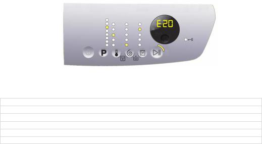
7.1.2Styling P3.0
When a problem arises with the appliance, “WARNING” appears on the LCD screen, represented by a code (three digits, indicating the time required for the cycle to end). At the same time the buzzer gives off three short “beeps” every 20” for a period of 5 minutes.
Once the fault has been repaired the buzzer does not give off any “beeps” and the selected programme appears on the LCD screen.
Alarms E9x and EHx show the entire code with the red LED + yellow LED, only alarm EHx is not accompanied by the buzzer sounding.
The alarms displayed to the user are listed below and can also be eliminated by the user:
E10 – Water fill difficulty (tap closed)
E20 – Drain difficulty (filter dirty)
E40 – Door open
EF0 – Excessive detergent (if displayed)
E91 – No communication between the display board and the main board.Switch ON/OFF
E92/E93/E94 – Main board not configured correctly.
EF0 – Water leakage (Aqua Control System)
It is displayed to the user, but technical assistance is required to resolve it.
EH0 – Voltage or frequency outside the normal values
It is necessary to wait for power supply voltage and/or frequency to restore nominal conditions.
The alarms are enabled during the execution of the washing programme. With the exception of alarms associated with the configuration and the power supply voltage/frequency, which are also displayed during the programme selection phase.
The door can normally be opened (except where specified) when an alarm condition has occurred, on the condition that:
The water in the tub is below a certain level. The water temperature is lower than 55 °C. The motor has stopped.
Certain alarm conditions require a drain phase to be performed before the door can be opened for safety reasons:
Cooling water fill if the temperature is higher than 65 °C
Drain until the analogue pressure switch is on empty, during a max. 3-minute interval.
Technical Support - MDM |
27/104 |
599 77 39-16 Rev. 00 |
Downloaded from www.Manualslib.com manuals search engine

7.2 Alarm reading/display
7.2.1Displaying the alarm (P3.0)
The last three alarms stored in the FLASH memory of the PCB can be displayed:
Enter the diagnostic mode (para. 6.1).
Irrespective of the type of circuit board and of the configuration, use sensor S1 to select the LED (see figure opposite) and the display indicates the last alarm.
To display previous alarms, touch the sensor closest to the START/PAUSE sensor in sequence (as shown in the figure)
To return to the last alarm, touch the START/PAUSE sensor.
7.2.2Displaying the alarm (P6)
The alarm is displayed by a repeated flashing sequence of the START/PAUSE button red and green lights (0.5 seconds on, 0.5 seconds off with a 2.5 second pause between sequences).
START/PAUSE button indicator with red light indicates the first digit of the alarm code (family).
START/PAUSE button indicator with yellow light indicates the second digit of the alarm code (number inside the family).
These two LEDs can be found on all models.
Notes:
The first letter of the alarm code “E” (Error) is not displayed, since this letter is common to all alarm codes. Alarm code families are expressed in hexadecimals; and therefore the letters:
A is represented by 10 flashes B is represented by 11 flashes
...
F is represented by 15 flashes
Configuration errors are displayed by all LEDs flashing (user interface not configured).
7.2.3Example of alarm display
If we take alarm E43 (problem with the door safety TRIAC) as an example; the following will be displayed: The sequence of four flashes of the START/PAUSE button with the red light indicates the first number E43.
The sequence of three flashes of the START/PAUSE button with the yellow light indicates the second number E43.
Technical Support - MDM |
28/104 |
599 77 39-16 Rev. 00 |
Downloaded from www.Manualslib.com manuals search engine

START/PAUSE button with red light |
START/PAUSE button with yellow light |
|||||
On/off |
Time |
Value |
On/off |
Time |
Value |
|
(Sec.) |
(Sec.) |
|||||
|
|
|
|
|||
|
0.5 |
|
|
0.5 |
|
|
|
|
1 |
|
|
1 |
|
|
0.5 |
|
0.5 |
|||
|
|
|
|
|||
|
|
|
|
|
|
|
|
0.5 |
|
|
0.5 |
|
|
|
|
2 |
|
|
2 |
|
|
0.5 |
|
0.5 |
|||
|
|
|
|
|||
|
|
|
|
|
|
|
|
0.5 |
|
|
0.5 |
3 |
|
|
|
3 |
|
|
||
|
0.5 |
|
0.5 |
|||
|
|
|
|
|||
|
|
|
|
|
|
|
|
0.5 |
4 |
|
|
|
|
|
|
|
|
|
||
|
0.5 |
|
2.5 |
Pause |
||
|
|
|
||||
|
|
|
|
|
|
|
|
1.5 |
Pause |
|
|
|
|
|
|
|
|
|
|
|
7.2.4Behaviour of the alarms during diagnostic testing
All alarms are enabled during diagnostic testing of the components.
Technical Support - MDM |
29/104 |
599 77 39-16 Rev. 00 |
Downloaded from www.Manualslib.com manuals search engine
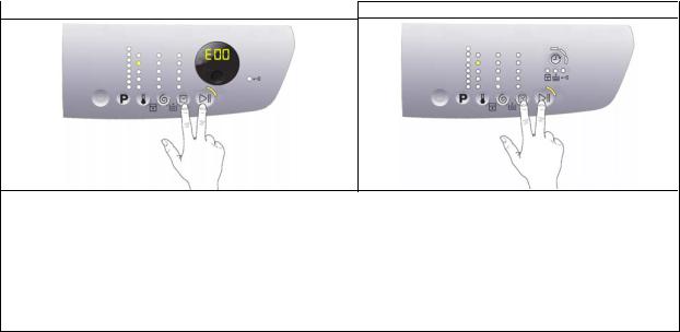
7.2.5Rapid reading of alarms
It is possible to display the last alarm even if the selector is not in the eleventh diagnostics position or the machine is in normal operation (e.g. while a washing programme is in progress):
→Touch the START/PAUSE sensor and the nearest option sensor simultaneously (as if you were entering DIAGNOSTIC mode) and hold for at least 2 seconds: the LCD display shows the last alarm.
→The alarm will continue to be displayed until a sensor is touched.
→The alarm reading system is as described in para. 7.2.
→While the alarm is being displayed, the appliance continues to perform the cycle or, if in the programme selection phase, it stores the previously selected options.
7.2.6Deleting the last alarm
It is good practice to cancel the alarms stored:
after reading the alarm codes, to check whether the alarm re-occurs during the diagnostic cycle
after repairing the appliance, to check whether it re-occurs during testing
P3.0 |
P6 |
S1 |
S1 |
|
Enter the diagnostic mode (para. 6.1).
Using sensor S1, select the position in which the LED lights up to display the alarms.
Simultaneously press the START/PAUSE sensor and the nearest option sensor (as shown in the diagram). Keep your finger above the sensors (for approximately 5 seconds) until for styling P3.0 the display shows “E00”, while for styling P6 the START/PAUSE LED stops flashing.
N.B. With this operation all the alarms stored are deleted.
Technical Support - MDM |
30/104 |
599 77 39-16 Rev. 00 |
Downloaded from www.Manualslib.com manuals search engine
 Loading...