


Troubleshooting Guide
|
1 |
6 |
2 |
2 |
5 |
1 |
|
|
|
3 |
4 |
MY09 PEC |
MY09 Inverter |
MY09 Motor Generator |
|
||
|
|
|
|
|
with Connectors |
Eaton Hybrid Drive Systems MY09
TRTS2000 EN-US
October 2015
MY09 PEC Models
EH-8E406A-U/P
EH-8E406A-UP
EH-8E406A-UPG
EH-8E406A-CD
EH-8E406A-CDG
EH-8E406A-CDR
EH-8E406A-T
EH-6E706B-CD
EH-6E706B-P
EH-6E706B-UPG

TRTS2000 |
Table of Contents | |
General Information
Warnings & Cautions . . . . . . . . . . . . . . . . . . . . . . . . . . 1 Warnings and Cautions . . . . . . . . . . . . . . . . . . . . . 1 High-Voltage Warnings & Cautions . . . . . . . . . . . . 2
Insulated Rubber Glove Test and High-Voltage Work Area . . . . . . . . . . . . . . . . . . . . . . . . . . . . . . . . . . . . . . . 3
Insulated Rubber Glove Test. . . . . . . . . . . . . . . . . . 3 High-Voltage Work Area Requirements . . . . . . . . . 3
High-Voltage Service Shutdown and Power-Up Procedure. . . . . . . . . . . . . . . . . . . . . . . . . . . . . . . . . . . 4
High-Voltage Service Shutdown Procedure . . . . . . 5 High-Voltage Service Power-Up Procedure . . . . . . 5 Diagnostic Tools and Service Publications. . . . . . . . . . 6 Eaton Tools. . . . . . . . . . . . . . . . . . . . . . . . . . . . . . . 6 SPX/OTC Tools . . . . . . . . . . . . . . . . . . . . . . . . . . . . 6 Service Publications . . . . . . . . . . . . . . . . . . . . . . . . 7 Hybrid Diagnostic Procedure . . . . . . . . . . . . . . . . . . . . 8 Hybrid Component and Connector Locations. . . . . . . . 9 Transmission Wiring Connections . . . . . . . . . . . . . 9 Component Wiring Connections. . . . . . . . . . . . . . 11 Fault Code Retrieval and Clearing. . . . . . . . . . . . . . . . 13 View Active and Inactive Faults. . . . . . . . . . . . . . . 13 Clear Inactive Faults . . . . . . . . . . . . . . . . . . . . . . . 13 Fault Code Isolation Procedure Index. . . . . . . . . . . . . 14 Symptom-Driven Diagnostics Index. . . . . . . . . . . . . . 17 Product Diagnostic Mode (PDM) . . . . . . . . . . . . . . . . 18
PDM will only work with the following Inactive codes . . . . . . . . . . . . . . . . . . . . . . . . . . . . . . . . . . 18
Hybrid Light and Gear Display Descriptions . . . . . . . . 19 Red “Service” Light . . . . . . . . . . . . . . . . . . . . . . . 19 Amber “Check Hybrid” Light . . . . . . . . . . . . . . . . 19 Red “Stop Hybrid” Light . . . . . . . . . . . . . . . . . . . . 19 Blinking Amber “Check Hybrid” Light. . . . . . . . . . 19 “ST” in Gear Display . . . . . . . . . . . . . . . . . . . . . . . 19 “PD” in Gear Display . . . . . . . . . . . . . . . . . . . . . . 19 “CA” in Gear Display. . . . . . . . . . . . . . . . . . . . . . . 20 “OS” in Gear Display . . . . . . . . . . . . . . . . . . . . . . 20 “F” in Gear Display . . . . . . . . . . . . . . . . . . . . . . . . 20 Dash “-” in Gear Display. . . . . . . . . . . . . . . . . . . . 20 Stars “**” in Gear Display . . . . . . . . . . . . . . . . . . 20 Two Dashes “- -” in Gear Display . . . . . . . . . . . . . 20 Blank Gear Display . . . . . . . . . . . . . . . . . . . . . . . . 20
Pretest Procedure
Power-Up Sequence Test . . . . . . . . . . . . . . . . . . . . . . 21
Electrical Pretest . . . . . . . . . . . . . . . . . . . . . . . . . . . . 24
Hybrid Electrical Pretest . . . . . . . . . . . . . . . . . . . . . . . 28
Fault Isolation Procedure
Fault Code 1 - Motor/Generator Current Sensor. . . . . 33 Fault Code 2 - Motor/Generator Temperature Sensor. 38 Fault Code 3 - Motor/Generator Temperature. . . . . . . 42 Fault Code 4 - Motor/Generator Rotation Speed
Sensor . . . . . . . . . . . . . . . . . . . . . . . . . . . . . . . . . . . . 48 Fault Code 5 - Motor/Generator AC Cable. . . . . . . . . . 54 Fault Code 6 - No HCM Operation . . . . . . . . . . . . . . . 60 Fault Code 7 - Improper HCM Configuration . . . . . . . 63 Fault Code 8 - Loss of Switched Ignition Power
Fault (HCM) . . . . . . . . . . . . . . . . . . . . . . . . . . . . . . . . 66 Fault Code 9 - Weak Battery Voltage . . . . . . . . . . . . . 70 Fault Code 10 - Low Battery Voltage (HCM). . . . . . . . 73 Fault Code 11 - No TECU Operation . . . . . . . . . . . . . . 76 Fault Code 12 - Improper ECU Configuration (TECU). 79 Fault Code 14 - Invalid Shifter Range . . . . . . . . . . . . . 82 Fault Code 16 - High Integrity Link (HIL) . . . . . . . . . . 87 Fault Code 17 - Start Enable Relay . . . . . . . . . . . . . . . 93 Fault Code 18 - ECA Communication Fault . . . . . . . . . 98 Fault Code 19 - CAN ECA Message Fault (HCM). . . . 101 Fault Code 22 - J1939 ABS Message Fault (HCM) . . 107 Fault Code 24 - J1939 HCM Message Fault (TECU) . 110 Fault Code 26 - Clutch Slip Fault . . . . . . . . . . . . . . . 114 Fault Code 27 - Clutch Disengagement Fault . . . . . . 117 Fault Code 32 - Loss of Switched Ignition
Power Fault (TECU) . . . . . . . . . . . . . . . . . . . . . . . . . 121 Fault Code 33 - Low Battery Voltage Fault (TECU) . . 124 Fault Code 34 - Weak Battery Voltage Fault (TECU) . 127 Fault Code 35 - J1939 Communication Link Fault (TECU) . . . . . . . . . . . . . . . . . . . . . . . . . . . . . . . . . . . 130 Fault Code 36 - J1939 Engine Message Faults . . . . . 135 Fault Code 37 - Power Supply Fault (TECU) . . . . . . . 138 Fault Code 38 - Battery Fan Relay Fault . . . . . . . . . . 142 Fault Code 39 - Heat Exchanger Relay Fault . . . . . . . 148 Fault Code 40 - Cooling Pump Relay Fault . . . . . . . . 153 Fault Code 48 - J1939 Transmission Message
Fault (HCM) . . . . . . . . . . . . . . . . . . . . . . . . . . . . . . . 159 Fault Code 49 - J1939 Engine Message Fault (HCM) 162 Fault Code 50 - J1939 Body Controller Message
Fault (HCM) . . . . . . . . . . . . . . . . . . . . . . . . . . . . . . . 165 Fault Code 51 - Rail Position Sensor Fault . . . . . . . . 168
2015.10.20 |
© 2013 Eaton. All rights reserved |
i

| Table of Contents |
TRTS2000 |
Fault Code 52 - Gear Position Sensor Fault . . . . . . . 173 Fault Code 53 - DC/DC Converter Fault . . . . . . . . . . 178 Fault Code 54 - DC/DC Converter Output Voltage
Fault. . . . . . . . . . . . . . . . . . . . . . . . . . . . . . . . . . . . . 181 Fault Code 56 - Input Shaft Speed Sensor Fault. . . . 186 Fault Code 58 - Output Shaft Speed Sensor Fault . . 190 Fault Code 59 - J1939 Communication Link Fault
(HCM) . . . . . . . . . . . . . . . . . . . . . . . . . . . . . . . . . . . 194 Fault Code 60 - CAN Communication Link Fault . . . 199 Fault Code 61: Rail Motor Circuit Fault . . . . . . . . . . 203 Fault Code 63: Gear Motor Circuit Fault . . . . . . . . . . 215 Fault Code 64 - ECA Fault . . . . . . . . . . . . . . . . . . . . 227 Fault Code 65 - ECA Speed Sensor Fault . . . . . . . . . 231 Fault Code 66 - ECA Battery Voltage Fault . . . . . . . . 235 Fault Code 67 - ECA Ignition Voltage Fault. . . . . . . . 238 Fault Code 68 - Grade Sensor Fault . . . . . . . . . . . . . 243 Fault Code 70 - Engine Failed to Respond Fault
(HCM) . . . . . . . . . . . . . . . . . . . . . . . . . . . . . . . . . . . 247 Fault Code 71 - Failed to Disengage a Gear . . . . . . . 250 Fault Code 72 - Failed to Select Rail Fault . . . . . . . . 254 Fault Code 73 - Failed to Engage a Gear Fault . . . . . 258 Fault Code 74 - Engine Failed to Respond Fault
(TECU) . . . . . . . . . . . . . . . . . . . . . . . . . . . . . . . . . . . 262 Fault Code 75 - Power Down in Gear . . . . . . . . . . . . 265 Fault Code 76 - High Voltage Battery 1 Potential Voltage. . . . . . . . . . . . . . . . . . . . . . . . . . . . . . . . . . . 268 Fault Code 78 - High Voltage Battery 1 Current Fault 271 Fault Code 82 - High Voltage Battery 1 Temperature Fault. . . . . . . . . . . . . . . . . . . . . . . . . . . . . . . . . . . . . 274 Fault Code 83 - Invalid Shift Range . . . . . . . . . . . . . 279 Fault Code 84 - Shift Control Device Not Configured Fault. . . . . . . . . . . . . . . . . . . . . . . . . . . . . . . . . . . . . 284 Fault Code 85 - Shift Control Device Incompatible
Fault. . . . . . . . . . . . . . . . . . . . . . . . . . . . . . . . . . . . . 290 Fault Code 88 - Inverter CAN Message Fault (HCM) 294 Fault Code 89 - Battery Control Unit CAN Message
Fault (HCM) . . . . . . . . . . . . . . . . . . . . . . . . . . . . . . . 300 Fault Code 94 - Transfer Case Message Fault . . . . . 308 Fault Code 95 - 12-Volt Cranking Relay Fault. . . . . . 311 Fault Code 97 - PTO Engagement Fault . . . . . . . . . . 316 Fault Code 101 - High Voltage Battery Fault. . . . . . . 322 Fault Code 103 - Battery Control Unit (BCU)
Communication Fault. . . . . . . . . . . . . . . . . . . . . . . . 325 Fault Code 105 - Battery Control Unit Fault . . . . . . . 329 Fault Code 107 - High Voltage Battery Leak
Detection Fault. . . . . . . . . . . . . . . . . . . . . . . . . . . . . 332 Fault Code 108 - Battery Control Unit Power
Supply Fault. . . . . . . . . . . . . . . . . . . . . . . . . . . . . . . 342
Fault Code 110 - Inverter Fault. . . . . . . . . . . . . . . . . 346 Fault Code 111 - Inverter CAN Message Fault
(HCM) . . . . . . . . . . . . . . . . . . . . . . . . . . . . . . . . . . . 349 Fault Code 112 - Inverter Voltage Fault . . . . . . . . . . 355 Fault Code 113 - Inverter Current Fault . . . . . . . . . . 359 Fault Code 114 - Inverter Power Supply Fault . . . . . 364 Fault Code 115 - Inverter Temperature Fault . . . . . . 368 Fault Code 116 - High Voltage Relays Fault . . . . . . . 373 Fault Code 117 - Battery Control Unit Relay Cut
Request Fault. . . . . . . . . . . . . . . . . . . . . . . . . . . . . . 382 Fault Code 118 - Auxiliary High Voltage Relay
Control Circuit Fault . . . . . . . . . . . . . . . . . . . . . . . . . 386 Fault Code 120 - APG Unit 1 - AC Voltage Fault . . . . 395 Fault Code 122 - APG Unit 1 Output . . . . . . . . . . . . 398 Fault Code 123 - APG Unit 1 High Voltage Battery. . 403 Fault Code 125 - APG Unit 1 - Over Temperature . . 406 Fault Code 126 - APG Unit 1 Configuration . . . . . . . 409 Fault Code 127 - APG Unit 1 Ambient Air Over Temperature . . . . . . . . . . . . . . . . . . . . . . . . . . . . . . 412 Fault Code 128 - APG Unit 1 CAN Fault . . . . . . . . . . 415 Fault Code 165 - APG Unit 1 Configuration Error. . . 419
Symptom Isolation Procedure
Front Box Test . . . . . . . . . . . . . . . . . . . . . . . . . . . . . 423
Engine Crank Test . . . . . . . . . . . . . . . . . . . . . . . . . . 428
Hybrid Performance Test . . . . . . . . . . . . . . . . . . . . . 432
ServiceRanger Test . . . . . . . . . . . . . . . . . . . . . . . . . 436
Gear Engagement Test. . . . . . . . . . . . . . . . . . . . . . . 441
ePTO Test . . . . . . . . . . . . . . . . . . . . . . . . . . . . . . . . 445
ii
© 2013 Eaton. All rights reserved |
2015.10.20 |

TRTS2000 |
Table of Contents | |
Appendix
Wiring Diagrams . . . . . . . . . . . . . . . . . . . . . . . . . . . 453
Hybrid Transmission ECU System Harness . . . . 453
Wiring Diagram with Push Button Shift
Controller . . . . . . . . . . . . . . . . . . . . . . . . . . . . . . 454
Connector Pin Description . . . . . . . . . . . . . . . . . . . . 456
Hybrid and Transmission Connector Pins. . . . . . 456
TECU and HCM Connectors . . . . . . . . . . . . . . . . 457
Transmission Controller 38-Way (Vehicle Interface
Connector) . . . . . . . . . . . . . . . . . . . . . . . . . . . . . 458
Hybrid Controller 38-Way (Vehicle Interface
Connector) . . . . . . . . . . . . . . . . . . . . . . . . . . . . . 459
Hybrid Controller 38-Way (Hybrid System Interface
Connector) . . . . . . . . . . . . . . . . . . . . . . . . . . . . . 460
Push Button Shift Control Connector . . . . . . . . . 461
Push Button 30-Way Connector . . . . . . . . . . . . . 461
Inverter Connectors . . . . . . . . . . . . . . . . . . . . . . 462
Power Electronics Carrier (PEC) Connectors . . . 464
PEC High-Voltage (DC) Connector to Inverter . . 465
Electric Clutch Actuator (ECA) Connectors . . . . . 466
Motor/Generator Connectors . . . . . . . . . . . . . . . 467
Typical DC/DC Converter Circuit . . . . . . . . . . . . . 469
2015.10.20 |
© 2013 Eaton. All rights reserved |
iii
Warnings & Cautions | General Information |
TRTS2000 |
Warnings & Cautions
Warnings and Cautions
Throughout this service manual there are paragraphs that are marked with a title of DANGER, WARNING, or CAUTION. These special paragraphs contain specific safety information and must be read, understood, and heeded before continuing the procedure or performing the step(s).
 DANGER
HAZARDOUS VOLTAGE
You will be severely injured or killed if you do not follow the procedure. Components marked with DANGER High Voltage should be avoided. Service must be
performed by qualified personnel only.
!Danger: Danger indicates you will be severely injured or killed if do not follow the indicated procedure.
!Warning: Warning indicates an immediate hazard, which could result in severe personal injury if you do not follow the indicated procedure.
!Caution: Caution indicates vehicle or property damage could occur if you do not follow the indicated procedure.
Note: Note indicates additional detail that will aid in the diagnosis or repair of a component/system.
!Caution: Follow the specified procedures in the indicated order to avoid personal injury:
1.If the high-voltage cones are around the vehicle and the lockout is installed on the PEC, the only person that should be allowed to start the vehicle is the person who signed the lockout tag.
2.Before working on a vehicle or leaving the cab while the engine is running, you should place the Shift Lever in “N” set the parking brake, and block the wheels.
3.For safety reasons, always engage the service brakes prior to selecting gear positions from “N.”
4.Before starting a vehicle always be seated in the driver's seat, select “N” on the shift control, and set the parking brakes.
5.In vehicles with ePTO, the engine and/or Motor/Generator can start in ePTO mode. Never perform any maintenance or work on vehicle, while in this mode.
6.12-volt Battery (+) and (-) must be disconnected prior to any welding on any Hybrid equipped vehicle.
!Caution: Follow the specified procedures in the indicated order to avoid equipment malfunction or damage.
!Caution: Do not release the parking brake or attempt to select a gear until the air pressure is at the correct level.
!Caution: To avoid damage to the transmission during towing place the Shift Lever in “N” and lift the drive wheels off the ground or disconnect the driveline.
1 |
© 2015 Eaton. All rights reserved |
2015.10.20 |
TRTS2000 |
General Information | Warnings & Cautions |
High-Voltage Warnings & Cautions
 DANGER
HAZARDOUS VOLTAGE
You will be severely injured or killed if you do not follow the procedure. Components marked with DANGER High Voltage should be avoided. Service must be
performed by qualified personnel only.
 WARNING
HAZARDOUS VOLTAGE
To reduce risk of possible serious injury (Shock, Burn or Death): Components marked with High Voltage should be avoided. Service must be performed by qualified personnel only.
•Use CO2 or Dry Chemical Fire Extinguishers.
•The high-voltage wiring is covered in orange insulation or convoluted tubing and marked with warning labels at the connectors.
•All Eaton® Hybrid Diesel/Electric vehicles will be marked 'Hybrid' on the outside of the vehicle, along with the shift label on the dash.
•Refer to OEM for specific location of chassis mounted hybrid components.
•Do NOT cut into the orange high-voltage cables.
•Do NOT cut into or open the Power Electric Carrier (PEC).
•Do NOT cut into or open the DC/DC converter.
•Do NOT cut into or open the Inverter.
A buffer zone must be set up and high-voltage insulated rubber gloves (class 0 with leather protectors) are required prior to working on high-voltage. Failure to follow these instructions may result in severe personal injury or death.
The rubber-insulated gloves that must be worn while working on the high-voltage system are class 0 with leather protectors. The rubber gloves should be tested before every use following the rubber insulation gloves testing procedure (see “Insulated Rubber Glove Test” on page 3). Failure to follow these instructions may result in severe personal injury or death.
Before inspecting or working on any high-voltage cables or components the “High-Voltage Service Shutdown Procedure” on page 5 should be followed. Failure to follow these instructions may result in severe personal injury or death.
The Lockout and Tag-out devices should only be removed by the technician that placed the Lockout and Tag-out devices on the vehicle. Failure to follow these instructions may result in severe personal injury or death.
High-voltage rubber insulated gloves (class 0 with leather protectors) must be worn when working on any high-voltage cables. The “High-Voltage Service Shutdown Procedure” on page 5 must be followed prior to removing any high-voltage cables. Failure to follow these instructions may result in severe personal injury or death.
High-voltage cables and wiring are orange and contain a warning label at the connectors. High-voltage components are marked with a label. High-voltage rubber insulated gloves (class 0 with leather protectors) must be used when working on any of these components. Failure to follow these instructions may result in severe personal injury
or death.
2015.10.20 |
© 2015 Eaton. All rights reserved |
2 |

Insulated Rubber Glove Test and High-Voltage Work Area | General Information TRTS2000
Insulated Rubber Glove Test and High-Voltage Work Area
Insulated Rubber Glove Test |
High-Voltage Work Area Requirements |
! Warning: The rubber-insulated gloves that must be worn |
! Warning: A buffer zone must be set up and ASTM Class 0 |
while working on the high-voltage system are class 0 with |
electrical insulating rubber gloves with leather protectors |
leather protectors. The rubber gloves should be tested |
are required prior to working on any high voltage. Failure to |
before EVERY use by following the procedure below. Failure |
follow these instructions may result in severe personal |
to follow these instructions may result in severe personal |
injury or death. |
injury or death. |
The buffer zone is required only when working on the |
|
|
The insulated rubber gloves that must be worn while |
high-voltage DC or AC systems and is called out both in the |
working on the high-voltage system are class 0 rated. |
“High-Voltage Service Shutdown Procedure” on page 5 and |
They must be inspected before each use and must always |
the individual repair procedures: |
be worn in conjunction with the leather outer glove: |
• Position the vehicle in the service bay. |
|
•Roll the glove up from the open end until the lower portion of the glove begins to balloon from the resulting air pressure. If the glove leaks any air it must not be used. Any hole in the insulated rubber glove is a potential entry point for high-voltage.
•The gloves should not be used if they exhibit any signs of wear and tear.
•The leather gloves must always be worn over the rubber insulating gloves in order to protect them.
•Position 4 orange cones around the corners of the vehicle to mark off a 1m (3 ft.) perimeter around the vehicle.
•Do not allow any unauthorized personnel into the buffer zone during repairs involving high voltage. Only personnel trained for service on the high-voltage system are permitted in the buffer zone.
•The rubber insulating gloves must be ASTM Class 0 electrical insulating rubber gloves with leather protectors.
3 |
© 2015 Eaton. All rights reserved |
2015.10.20 |
High-Voltage Service Shutdown and Power-Up Procedure | General Information |
TRTS2000 |
High-Voltage Service Shutdown and Power-Up Procedure
 WARNING
HAZARDOUS VOLTAGE
To reduce risk of possible serious injury (Shock, Burn or Death): Components marked with High Voltage should be avoided. Service must be performed by qualified personnel only.
 DANGER
HAZARDOUS VOLTAGE
You will be severely injured or killed if you do not follow the procedure. Components marked with DANGER High Voltage should be avoided. Service must be
performed by qualified personnel only.
A buffer zone must be set up and ASTM Class 0 electrical insulating rubber gloves with leather protectors are required prior to working on high-voltage. Failure to follow these instructions may result in severe personal injury or death.
The rubber-insulated gloves that must be worn while working on the high-voltage system are class 0 with leather protectors. The rubber gloves should be tested before use following the rubber insulation gloves testing procedure (see “Insulated Rubber Glove Test” on page 3). Failure to follow these instructions may result in severe personal injury or death.
Before inspecting or working on any high-voltage cables or components the “High-Voltage Service Shutdown Procedure” on page 5 should be followed. Failure to follow these instructions may result in severe personal injury or death.
The lockout and Tag-out devices should only be removed by the technician that placed the Lockout Tag-out devices on the vehicle. Failure to follow these instructions may result in severe personal injury or death.
ASTM Class 0 electrical insulating rubber gloves with leather protectors must be worn when working on any highvoltage cables. The “High-Voltage Service Shutdown Procedure” on page 5 must be followed prior to removing any high-voltage cables. Failure to follow these instructions may result in severe personal injury or death.
High-voltage cables and wiring are orange and contain a warning label at the connectors. High-voltage components are marked with a label. ASTM Class 0 electrical insulating rubber gloves with leather protectors must be used when working on any of these components. Failure to follow these instructions may result in severe personal injury or death.
4 |
© 2015 Eaton. All rights reserved |
2015.10.20 |
High-Voltage Service Shutdown and Power-Up Procedure | General Information |
TRTS2000 |
|
|
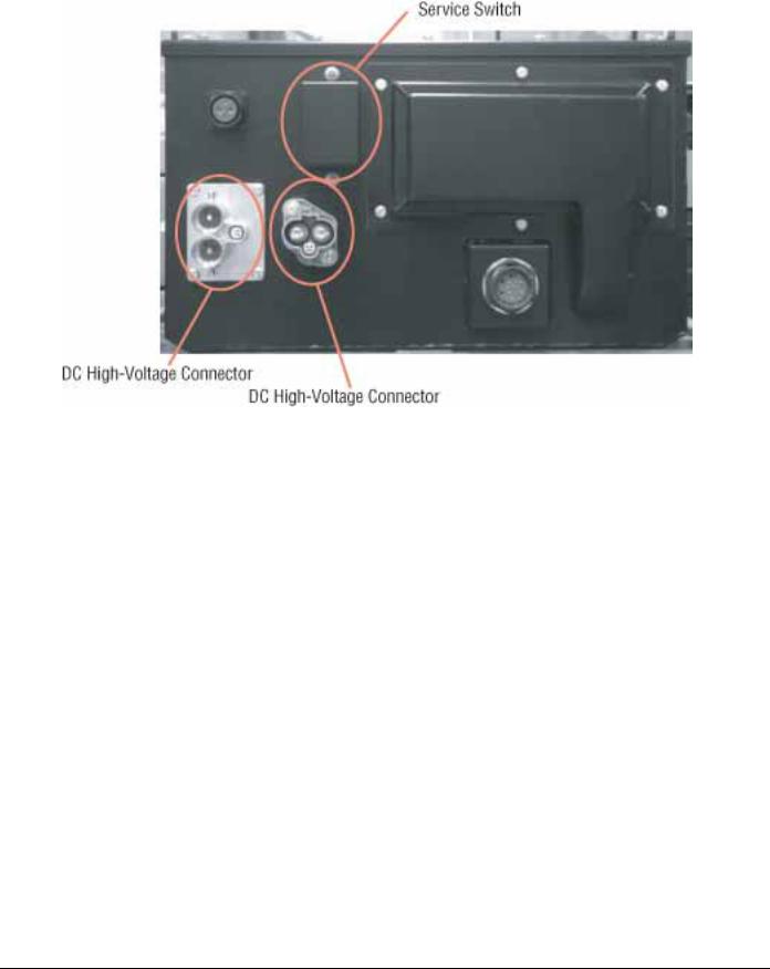
High-Voltage Service Shutdown
Procedure
1.Follow “High-Voltage Work Area” procedure (see “High-Voltage Work Area Requirements” on page 3).
2.Locate the red Power Electric Carrier (PEC) service switch on the front of the PEC and push to the Off position.
3.Remove the service switch cover and install the Lockout Bracket (J48506).
4.Fasten tag to the Lockout Bracket.
5.Ensure the PEC service switch cannot move from the Off position.
6.Allow the system to set for a minimum of 5 minutes to discharge high-voltage.
7.Connect ServiceRanger and view the Data Monitor PID 116 “High-Voltage Battery Potential.” Use SPN 520323 for J1939 connection “Battery Voltage RB” (Relay Box).
8.The voltage should be 30 volts or less. If the voltage is above 30 volts, do not work on the vehicle and contact Eaton® at 1-800-826-HELP (4357).
9.Turn ignition key off and proceed to repair or troubleshooting step.
Note: The voltage drops to 0 when the key is turned off.
High-Voltage Service Power-Up
Procedure
1.Install all high-voltage connectors back into their locked positions.
2.Remove the Lockout Bracket and tag ONLY IF
YOU ARE THE PERSON WHO IS WORKING ON THE VEHICLE.
3.Reinstall the protection bracket over the service switch.
4.Pull the service switch out and let vehicle set for 2 minutes.
5.Start vehicle when appropriate.
5 |
© 2015 Eaton. All rights reserved |
2015.10.20 |
Diagnostic Tools and Service Publications | General Information |
TRTS2000 |
Diagnostic Tools and Service Publications
Eaton Tools
• Visit Roadranger.com
Tool |
Description |
|
|
|
|
ServiceRanger version 3 |
ServiceRanger PC-based Diagnostic Tool |
|
|
ServiceRanger version 4 |
ServiceRanger PC-based Diagnostic Tool |
|
|
SPX/OTC Tools
•Contact SPX / OTC at (800) 328-6657
Tool |
Description |
|
|
J49818 |
Eaton Hybrid Tool Safety Kit - Basic PPE (Items listed below can be ordered separately) |
|
|
J48603 |
ASTM Class 0 electrical insulating rubber gloves with leather protectors (1000 volt) |
|
|
J48605 |
Hybrid Safety Cones (set of 4) |
|
|
J48506 |
Lockout Switch Plate |
|
|
J48906 |
Lockout Tags (per 25) |
|
|
Tool |
Description |
|
|
J49819 |
Eaton Hybrid Tool Safety Kit - Basic Plus PPE (Items listed below can be ordered separately) |
|
|
J48603 |
ASTM Class 0 electrical insulating rubber gloves with leather protectors (1000 volt) |
|
|
J48605 |
Hybrid Safety Cones (set of 4) |
|
|
J48506 |
Lockout Switch Plate |
|
|
J48906 |
Lockout Tags (per 25) |
|
|
J48907 |
Orange Magnetic Sign |
|
|
J48608 |
Hybrid Non-Conductive Safety Pole |
|
|
J48908 |
Glove Bag |
|
|
6 |
© 2015 Eaton. All rights reserved |
2015.10.20 |

Diagnostic Tools and Service Publications | General Information |
TRTS2000 |
|
|
Tool |
Description |
|
|
Misc. Service Tools |
Items listed below are ordered separately |
|
|
J48624 |
Nexiq USB-Link Communication Adapter |
|
|
J43318-A* |
Pin Adapter Kit - Interface Harness Diagnostics |
|
|
J48735* |
Alignment Pins - Hybrid Motor/Gen to Transmission Main Case |
|
|
AMB-45* |
Digital Megohmmeter - High-Voltage Leakage Detection |
|
|
J49111* |
Clutch Alignment Tool |
|
|
J46708* |
Fluke Digital Multimeter |
|
|
J48505 |
Input Shaft Turning Socket |
|
|
J48507 |
Lifting Fixture - Power Electronics Carrier |
|
|
J48502 |
Jack Adapter Plate - Hybrid Drive Unit |
|
|
5019 |
Transmission Jack - Low Lift |
|
|
5078 |
Transmission Jack - High Lift |
|
|
J48577 |
Engine/Transmission Stand Adapter Plate - Hybrid Drive Unit |
|
|
J29109-A |
Engine/Transmission Stand - 6000 lb. Rating |
|
|
Tool |
Description |
|
|
J48893 |
Hybrid PPE/Service Tool Kit (includes J49819 kit and items from Miscellaneous Service Tools |
|
highlighted with *) |
|
|
Service Publications |
|
1. Visit Roadranger.com |
|
|
|
TRSM2000 |
Service Manual (covers external components on transmission and hybrid components) |
|
|
TRSM0110 |
Service Manual (covers internal transmission repairs only) |
|
|
TRTS2000 |
Troubleshooting Guide |
|
|
TRTS2001 |
Troubleshooting Guide for Alternative PEC and Alternative APG |
|
|
TRDR1000 |
Drivers Instructions |
|
|
TRDR1110 |
First Responder Guide |
|
|
CLMT-0365 |
Eaton 365 mm Clutch Installation Procedure |
|
|
7 |
© 2015 Eaton. All rights reserved |
2015.10.20 |

Hybrid Diagnostic Procedure | General Information |
TRTS2000 |
Hybrid Diagnostic Procedure
Note: If ServiceRanger fails to communicate, go to “ServiceRanger Test” (page 178)
Go to “Engine Crank
Test” (page 171)
Go to "ePTO Test” (page 187)
Go to "Gear Engagement Test” if solid “N” is displayed (page 183)
Go to “Front Box Test” if flashing gear number is displayed (page 167)
Go to "Hybrid Performance Test" (page 175)
|
|
|
Key ON |
|
|
|
|
|
|
|
|
|
|
|
|
|
|
|
||
|
|
|
|
|
|
|
|
|
|
|
|
|
|
|
|
|
|
|
|
|
|
|
|
|
|
|
|
|
|
|
|
|
|
||||||||
|
Is Red "Stop Hybrid" or |
|
|
|
|
|
|
|
|
|
|
|
||||||||
|
Amber “Check Hybrid” |
|
|
|
|
Go to “Hybrid Light and |
|
|||||||||||||
|
|
|
lamp blinking? |
|
|
|
Yes |
|
|
Gear Display Descriptions” |
|
|
|
|||||||
|
|
|
|
|
|
|
|
|
|
|
||||||||||
|
|
|
No |
|
|
|
|
|
|
|
|
|
(page 20) |
|
|
|
||||
|
Retrieve Active Faults |
|
|
|
|
|
|
|
|
|
|
|
|
|||||||
|
with ServiceRanger |
|
|
|
|
|
|
|
|
|
|
|
|
|
|
|
||||
|
|
|
|
|
|
|
|
|
|
|
|
|
|
|
|
|
|
|
|
|
|
|
|
|
|
|
|
|
|
|
|
|
|
|
|
|
|
|
|
|
|
|
|
|
Active Codes? |
|
Yes |
|
Go to "Fault Code Isolation Procedure |
|||||||||||||
|
|
|
|
|
|
|
|
|
Index" (page 17) |
|||||||||||
|
|
|
|
|
|
|
|
|
|
|
|
|
|
|
||||||
|
|
|
|
|
|
|
|
|
|
|
|
|
|
|
|
|
|
|
|
|
|
|
|
No |
|
|
|
|
|
|
|
|
|
|
|
|
|
|
|
||
|
Does Gear Display |
|
|
|
No |
|
|
|
Go to “Hybrid Light and |
|
|
|||||||||
|
|
|
Show an "N”? |
|
|
|
|
|
Gear Display Descriptions” |
|
|
|||||||||
|
|
|
|
|
|
|
|
|
|
|
|
|
|
|
(page 20) |
|
|
|||
|
|
|
Yes |
|
|
|
|
|
||||||||||||
|
|
|
|
|
|
|
|
|
|
|
|
|
|
|
|
|
|
|||
|
|
|
|
|
|
|
|
|
|
|
|
|
|
|
|
|
|
|
|
|
No |
Does Engine Crank? |
|
|
|
|
|
|
|
|
|
|
|
|
|
|
|
||||
|
|
|
|
|
|
|
|
|
|
|
|
|
|
|
|
|
|
|
|
|
|
|
|
Yes |
|
|
|
|
|
|
|
|
|
|
|
|
|
|
|
||
|
|
|
|
|
|
|
|
|
|
|
|
|
|
|
|
|
|
|
||
No |
|
If equipped, does |
|
|
|
|
|
|
|
|
|
|
|
|
|
|
|
|||
|
|
vehicle operate |
|
|
|
|
|
|
|
|
|
|
|
|
|
|
|
|||
|
normal in ePTO mode? |
|
|
|
|
|
|
|
|
|
|
|
||||||||
|
|
|
|
|
|
|
|
|
|
|
|
|
|
|
|
|
|
|
|
|
|
|
|
Yes |
|
|
|
|
|
|
|
|
|
|
|
|
|
|
|
||
|
|
|
|
|
|
|
|
|
|
|
|
|
|
|||||||
|
If a mode other than neutral is selected does |
|
|
|
|
|
||||||||||||||
No |
|
|
transmission engage a gear? |
|
|
|
|
|||||||||||||
|
NOTE: Service Brake must be applied |
|
|
|
|
|
||||||||||||||
|
|
|
|
|
|
|||||||||||||||
|
|
|
prior to selecting a gear. |
|
|
|
|
|||||||||||||
|
|
|
Yes |
|
|
|
|
|
|
|
|
|
|
|
|
|
|
|
||
|
|
|
|
|
|
|
|
|
|
|
|
|
||||||||
|
|
|
Will vehicle move |
|
|
|
No |
|
|
Go to “Gear Engagement |
|
|
|
|
||||||
|
|
|
from a stop? |
|
|
|
|
|
|
|
Test” (page 183) |
|
|
|
|
|||||
|
|
|
|
|
|
|
|
|
|
|
|
|
||||||||
|
|
|
|
|
|
|
|
|
|
|
|
|
|
|
|
|
|
|
||
|
|
|
Yes |
|
|
|
|
|
|
|
|
|
|
|
|
|
|
|
||
|
|
|
|
|
|
|
|
|
|
|
|
|
|
|
|
|
|
|||
|
|
|
|
|
|
|
|
|
|
|
|
|
|
|
|
|||||
No |
Is vehicle acceleration |
|
|
|
|
|
|
|
|
|
|
|
|
|||||||
performance acceptable? |
|
|
|
|
|
|
|
|
|
|
|
|
||||||||
|
|
|
|
|
|
|
Inactive Faults = Go |
|
||||||||||||
|
|
|
|
|
|
|
|
|
|
|
|
|
|
|
|
|||||
|
|
|
|
|
|
|
|
|
|
|
|
|
|
|
to “Product |
|
||||
|
|
|
Yes |
|
|
|
|
|
|
|
||||||||||
|
|
|
|
|
|
|
|
|
|
|
|
Diagnostic Mode (PDM)” |
|
|||||||
|
|
|
|
|
|
|
|
|
|
|
|
|
|
|
|
|||||
|
|
|
Clear faults and |
|
|
|
|
|
|
|
|
|
(page 19) |
|
||||||
|
|
|
|
|
|
|
|
|
|
|
|
|
|
|
|
|
|
|||
|
|
|
operate vehicle |
|
|
|
|
|
|
|
|
|
Active Faults = Go to |
|
||||||
|
based on customers |
|
|
|
|
|
|
|
|
|
“Fault Code Isolation |
|
||||||||
|
|
|
|
|
|
|
|
|
|
|
||||||||||
|
|
|
concern |
|
|
|
|
|
|
|
|
|
Procedure Index” |
|
||||||
|
|
|
|
|
|
|
|
|
|
|
|
|
|
|
(page 17) |
|
||||
|
|
|
|
|
|
|
|
|
|
|
|
|
||||||||
|
|
|
|
|
|
|
|
|
|
|
|
|
|
|
No Fault = Test |
|
||||
|
|
|
|
|
|
|
|
|
|
|
|
|
|
|
Complete |
|
||||
|
|
|
|
|
|
|
|
|
|
|
|
|
|
|
|
|
|
|
|
|
8 |
© 2015 Eaton. All rights reserved |
2015.10.20 |

Hybrid Component and Connector Locations | General Information |
TRTS2000 |
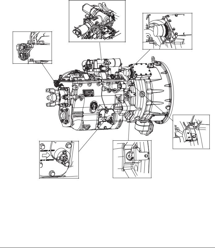
Hybrid Component and Connector Locations
Transmission Wiring Connections
Electronic Clutch Actuator
Top: 3-Way Connector
Bottom: 8-Way Connector
Transmission Electronic Control Unit (TECU) |
Left: 38-Way Vehicle Connector
Right: 38-Way System Connector
Rail Position Sensor |
Output Shaft Speed Sensor |
Hybrid Control Module (HCM)
Left: 38-Way System Connector
Right: 38-Way Vehicle Connector
9 |
© 2015 Eaton. All rights reserved |
2015.10.20 |
TRTS2000 |
General Information | Hybrid Component and Connector Locations |
|
|
XY Shifter
High-Voltage 3-Way AC Connector
Transmission Diagnostic Port |
Input Shaft Speed Sensor |
Motor/Generator |
Resolver Connector |
Motor/Generator |
Temperature Connector |
2015.10.20 |
© 2015 Eaton. All rights reserved |
10 |
Hybrid Component and Connector Locations | General Information |
TRTS2000 |
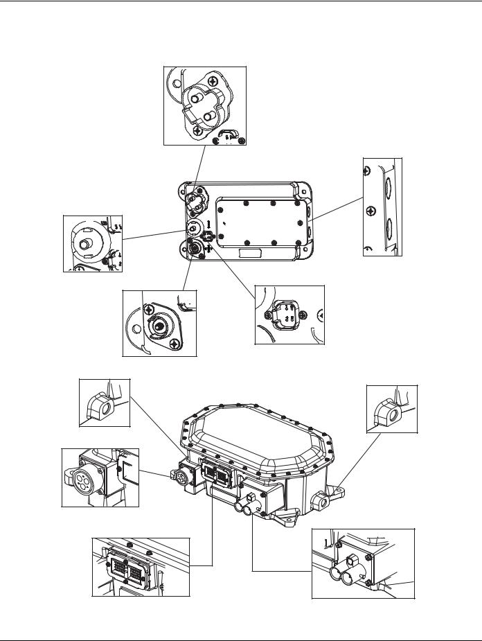
Component Wiring Connections
High Voltage DC Connector
Top: DC(-)
Bottom: (DC(+)
(-) (+) |
12V DC(-)
 DC/DC Converter
Coolant Ports
12V DC(+) |
OEM Connection |
|
Coolant Port Outlet |
Inverter
HIgh Voltage 3-Way AC Connector
Low Voltage 40-Way Connector |
Coolant Port Inlet |
High-Voltage DC Connector to PEC
11 |
© 2015 Eaton. All rights reserved |
2015.10.20 |
TRTS2000 |
General Information | Hybrid Component and Connector Locations |
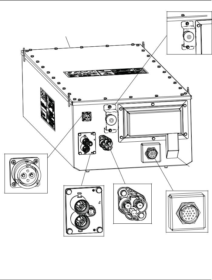
Power Electronics Carrier (PEC)
Air Exhaust (not shown)
Red Service Switch with Cover
Air Intake
DC Connector to
APG (Optional)
DC Connector to
DC/DC Converter
19-Pin Low-Voltage Connector
DC Connector to Inverter
2015.10.20 |
© 2015 Eaton. All rights reserved |
12 |

Fault Code Retrieval and Clearing | General Information |
TRTS2000 |
Fault Code Retrieval and Clearing
All Eaton® Hybrid systems require the use of ServiceRanger for all diagnostics. To view fault codes or clear them, follow the procedures below.
View Active and Inactive Faults
1.Connect ServiceRanger to the 9-Way Diagnostic Connector.
2.Go to the Tools menu and select the “Communication” tab.
3.Select the appropriate communication device for J1587 and J1939.
4.Select “Connect” on the main page.
5.Select the “View Fault Codes” tab.
Note: Initial use requires all steps; however, subsequent uses require only steps 4 and 5.
Clear Inactive Faults
1.Connect ServiceRanger to the 9-Way Diagnostic Connector.
2.Go to the Tools menu and select the “Communication” tab.
3.Select the appropriate communication device for J1587 and J1939.
4.Select “Connect” on the main page.
5.Select the “View Fault Codes” tab.
6.Select the “Clear Faults” button.
Note: Initial use requires all steps, however subsequent uses require only steps 4 and 5.
13 |
© 2015 Eaton. All rights reserved |
2015.10.20 |

Fault Code Isolation Procedure Index | General Information TRTS2000
Fault Code Isolation Procedure Index
Fault Code |
SPN |
FMI |
Description |
Page Number |
|
|
|
|
|
1 |
520225 |
0, 6, 15 |
Motor/Generator Current Sensor |
page 33 |
|
|
|
|
|
2 |
520226 |
3 |
Motor/Generator Temperature Sensor |
page 38 |
|
|
|
|
|
3 |
520227 |
0 |
Motor/Generator Temperature |
page 42 |
|
|
|
|
|
4 |
520228 |
0, 2, 21–27 |
Motor/Generator Rotation Speed Sensor |
page 48 |
|
|
|
|
|
5 |
520229 |
21–29 |
Motor/Generator AC Cable |
page 54 |
|
|
|
|
|
6 |
629 |
13 |
No ECU Operation (HCM) |
page 60 |
|
|
|
|
|
7 |
629 |
13 |
Improper ECU Configuration (HCM) |
page 63 |
|
|
|
|
|
8 |
158 |
4 |
Loss of Switched Ignition Power Fault (HCM) |
page 66 |
|
|
|
|
|
9 |
168 |
14 |
Weak Battery Voltage (HCM) |
page 70 |
|
|
|
|
|
10 |
168 |
4 |
Low Battery Voltage (HCM) |
page 73 |
|
|
|
|
|
11 |
629 |
12 |
No ECU Operation (TECU) |
page 76 |
|
|
|
|
|
12 |
629 |
13 |
Improper ECU Configuration (TECU) |
page 79 |
|
|
|
|
|
14 |
751 |
2, 3, 4 |
Invalid Shifter Range |
page 82 |
|
|
|
|
|
16 |
625 |
2 |
High Integrity Link (HIL) |
page 87 |
|
|
|
|
|
17 |
626 |
3, 4 |
Start Enable Relay |
page 93 |
|
|
|
|
|
18 |
520200 |
2, 9 |
ECA Communication |
page 98 |
|
|
|
|
|
19 |
520273 |
2, 9 |
CAN ECA Message |
page 101 |
|
|
|
|
|
22 |
563 |
2, 9, 14 |
J1939 ABS Message (HCM) |
page 107 |
|
|
|
|
|
24 |
525 |
9 |
J1939 HCM Message (TECU) |
page 110 |
|
|
|
|
|
26 |
522 |
10 |
Clutch Slip |
page 114 |
|
|
|
|
|
27 |
788 |
7, 14 |
Clutch Disengagement |
page 117 |
|
|
|
|
|
32 |
43 |
2 |
Loss of Switched Ignition Power (TECU) |
page 121 |
|
|
|
|
|
33 |
168 |
4 |
Low Battery Voltage (TECU) |
page 124 |
|
|
|
|
|
34 |
168 |
14 |
Weak Battery Voltage (TECU) |
page 127 |
|
|
|
|
|
35 |
639 |
2 |
J1939 Communication Link |
page 130 |
|
|
|
|
|
36 |
639 |
14 |
J1939 Engine Message (TECU) |
page 135 |
|
|
|
|
|
37 |
610 |
5 |
Power Supply (TECU) |
page 138 |
|
|
|
|
|
38 |
520243 |
3, 4, 5, 14 |
Battery Fan Relay |
page 142 |
|
|
|
|
|
39 |
520247 |
3, 4, 5 |
Heat Exchanger Relay |
page 148 |
|
|
|
|
|
40 |
520248 |
3, 4, 5, 14 |
Cooling Pump Relay |
page 153 |
|
|
|
|
|
48 |
523 |
2, 9 |
J1939 Transmission Message (HCM) |
page 159 |
|
|
|
|
|
49 |
190 |
2, 9 |
J1939 Engine Message (HCM) |
page 162 |
|
|
|
|
|
50 |
701 |
2, 9 |
J1939 Body Controller Message (HCM) |
page 165 |
|
|
|
|
|
51 |
60 |
2, 3, 4, 10 |
Rail Position Sensor |
page 168 |
|
|
|
|
|
52 |
59 |
2, 3, 4 |
Gear Position Sensor |
page 173 |
|
|
|
|
|
53 |
520244 |
12, 14 |
DC/DC Converter |
page 178 |
|
|
|
|
|
54 |
520245 |
2, 4 |
DC/DC Converter Output Voltage |
page 181 |
|
|
|
|
|
14 |
© 2015 Eaton. All rights reserved |
2015.10.20 |

Fault Code Isolation Procedure Index | General Information |
TRTS2000 |
|||||
|
|
|
|
|
|
|
|
|
|
|
|
|
|
|
Fault Code |
SPN |
FMI |
Description |
Page Number |
|
|
|
|
|
|
|
|
|
56 |
161 |
2, 3, 4, 5, |
Input Shaft Speed Sensor |
page 186 |
|
|
|
|
10 |
|
|
|
|
|
|
|
|
|
|
|
58 |
191 |
2, 3, 4, 5 |
Output Shaft Speed Sensor |
page 190 |
|
|
|
|
|
|
|
|
|
59 |
639 |
2, 9 |
J1939 Communication Link (HCM) |
page 194 |
|
|
|
|
|
|
|
|
|
60 |
625 |
2, 9 |
CAN Communication Link (HCM) |
page 199 |
|
|
|
|
|
|
|
|
|
61 |
772 |
5, 6 |
Rail Select Motor |
page 203 |
|
|
|
|
|
|
|
|
|
63 |
773 |
5, 6 |
Gear Select Motor |
page 215 |
|
|
|
|
|
|
|
|
|
64 |
788, 520198, |
0, 12, 13, |
ECA |
page 227 |
|
|
|
520199, 524035 |
21–28 |
|
|
|
|
|
|
|
|
|
|
|
65 |
520203 |
2, 5 |
ECA Speed Sensor |
page 231 |
|
|
|
|
|
|
|
|
|
66 |
520271 |
3, 4, 14 |
ECA Battery Voltage |
page 235 |
|
|
|
|
|
|
|
|
|
67 |
520274 |
3, 4, 5 |
ECA Ignition Voltage |
page 238 |
|
|
|
|
|
|
|
|
|
68 |
520231 |
12, 13, 14 |
Grade Sensor |
page 243 |
|
|
|
|
|
|
|
|
|
70 |
188, 518, 539, 544 |
0, 1, 2, 7 |
Engine Failed to Respond (HCM) |
page 247 |
|
|
|
|
|
|
|
|
|
71 |
520275 |
7 |
Failed to Disengage Gear |
page 250 |
|
|
|
|
|
|
|
|
|
72 |
520277 |
7 |
Failed to Select Rail |
page 254 |
|
|
|
|
|
|
|
|
|
73 |
520278 |
7 |
Failed to Engage Gear |
page 258 |
|
|
|
|
|
|
|
|
|
74 |
93, 190 |
7 |
Engine Failed to Respond (TECU) |
page 262 |
|
|
|
|
|
|
|
|
|
75* |
520276 |
14 |
Power Down In Gear |
page 265 |
|
|
|
|
|
|
|
|
|
76 |
520250 |
3, 4, 16, 18 |
High-Voltage Battery 1 Potential Voltage |
page 268 |
|
|
|
|
|
|
|
|
|
78 |
520232 |
6 |
High-Voltage Battery 1 Current |
page 271 |
|
|
|
|
|
|
|
|
|
82 |
520233 |
0, 16 |
High-Voltage Battery 1 Temperature |
page 274 |
|
|
|
|
|
|
|
|
|
83 |
751 |
12, 13 |
Invalid Shifter Range |
page 279 |
|
|
|
|
|
|
|
|
|
84 |
751 |
13 |
Shift Control Device Not Configured |
page 284 |
|
|
|
|
|
|
|
|
|
85 |
639 |
12 |
Shift Control Device Incompatible |
page 290 |
|
|
|
|
|
|
|
|
|
88 |
520223 |
2, 9 |
Inverter CAN Message (HCM) |
page 294 |
|
|
|
|
|
|
|
|
|
89 |
520234 |
2, 9 |
PEC CAN Message (HCM) |
page 300 |
|
|
|
|
|
|
|
|
|
94 |
520237 |
9 |
Transfer Case Message |
page 308 |
|
|
|
|
|
|
|
|
|
95 |
520249 |
3, 4 |
12-volt Cranking Relay |
page 311 |
|
|
|
|
|
|
|
|
|
97 |
3460 |
3, 4, 5, 7, |
PTO Engagement |
page 316 |
|
|
|
|
14 |
|
|
|
|
|
|
|
|
|
|
|
101 |
520238 |
0, 22–31 |
High-Voltage Battery |
page 322 |
|
|
|
|
|
|
|
|
|
103 |
520265 |
22–26 |
Battery Control Unit Communication |
page 325 |
|
|
|
|
|
|
|
|
|
105 |
520240 |
22–30 |
Battery Control Unit |
page 329 |
|
|
|
|
|
|
|
|
|
107 |
520242 |
1 |
High-Voltage Battery Leak Detection |
page 332 |
|
|
|
|
|
|
|
|
|
108 |
520268 |
3, 4 |
Battery Control Unit Power Supply |
page 342 |
|
|
|
|
|
|
|
|
|
110 |
520220 |
21–29 |
Inverter |
page 346 |
|
|
|
|
|
|
|
|
|
111 |
520260 |
12–28 |
Inverter Communication |
page 349 |
|
|
|
|
|
|
|
|
|
112 |
520221 |
3, 4 |
Inverter Voltage |
page 355 |
|
|
|
|
|
|
|
|
15 |
© 2015 Eaton. All rights reserved |
2015.10.20 |
TRTS2000 |
|
|
General Information | Fault Code Isolation Procedure Index |
|||
|
|
|
|
|
|
|
|
|
|
|
|
|
|
|
Fault Code |
SPN |
FMI |
Description |
Page Number |
|
|
|
|
|
|
|
|
|
113 |
520222 |
6, 14 |
Inverter Current |
page 359 |
|
|
|
|
|
|
|
|
|
114 |
520261 |
3, 4 |
Inverter Power Supply |
page 364 |
|
|
|
|
|
|
|
|
|
115 |
520223 |
0 |
Inverter Temperature |
page 368 |
|
|
|
|
|
|
|
|
|
116 |
521210, 521211, |
3, 4, 5 |
High-Voltage Relays |
page 373 |
|
|
|
521212 |
|
|
|
|
|
|
|
|
|
|
|
|
116 |
520224 |
10, 14, 20 |
High-Voltage Relays |
page 373 |
|
|
|
|
|
|
|
|
|
117 |
520251 |
3, 14, 29 |
PEC Relay Cut Request |
page 382 |
|
|
|
|
|
|
|
|
|
118 |
520252 |
3, 4, 5 |
Auxiliary High-Voltage Relay Control Circuit |
page 386 |
|
|
|
|
|
|
|
|
|
120 |
520275 |
3, 4 |
APG Unit 1 - AC Voltage |
page 395 |
|
|
|
|
|
|
|
|
|
122 |
520277 |
6, 14, 15 |
APG Unit 1 - Output |
page 398 |
|
|
|
|
|
|
|
|
|
123 |
520278 |
3, 4 |
APG Unit 1 - High Voltage Battery |
page 403 |
|
|
|
|
|
|
|
|
|
125 |
520280 |
0 |
APG Unit 1 - Over Temperature |
page 406 |
|
|
|
|
|
|
|
|
|
126 |
520281 |
25, 26, 27 |
APG Unit - Configuration |
page 409 |
|
|
|
|
|
|
|
|
|
127 |
520282 |
0 |
APG Unit 1 - Ambient Air Over Temperature |
page 412 |
|
|
|
|
|
|
|
|
|
128 |
520283 |
9 |
APG Unit 1 - CAN |
page 415 |
|
|
|
|
|
|
|
|
|
165 |
520320 |
2 |
APG Unit 1 -Configuration Error |
page 419 |
|
|
|
|
|
|
|
|
2015.10.20 |
© 2015 Eaton. All rights reserved |
16 |

Symptom-Driven Diagnostics Index | General Information TRTS2000
Symptom-Driven Diagnostics Index
Symptom |
Isolation Procedure |
Page Number |
|
|
|
Power-up no crank and gear display shows a dash “-” |
Front Box Test |
page 423 |
|
|
|
Power-up no crank and gear display shows a “N” |
Engine Crank Test |
page 428 |
|
|
|
Power-up no crank and gear display shows double |
Power Up Sequence Test |
page 21 |
dash “--”, double stars “**” or blank |
|
|
|
|
|
Power-up vehicle cranks and gear display shows “--”, |
Refer to OEM for gear display issue |
N/A |
“**” or blank |
|
|
|
|
|
Vehicle acceleration performance is not acceptable |
Hybrid Performance Test |
page 432 |
|
|
|
Transmission will not engage a gear from neutral and |
Gear Engagement Test |
page 441 |
warning tone sounds (solid N in gear display) |
|
|
|
|
|
Transmission will not move from a stop (solid gear |
Gear Engagement Test |
page 441 |
number in gear display) |
|
|
|
|
|
Transmission will not engage a gear from neutral |
Front Box Test |
page 423 |
(flashing gear number in gear display). |
|
|
|
|
|
Red Service light on the Push Button Shift Control is |
Fault Code Retrieval and Clearing |
page 13 |
on/blinking |
|
|
|
|
|
Amber “Check Hybrid” light on the dash is on |
Fault Code Retrieval and Clearing |
page 13 |
|
|
|
Red “Stop Hybrid” light on the dash is on |
Fault Code Retrieval and Clearing |
page 13 |
|
|
|
ePTO mode does not operate as expected |
ePTO Test |
page 445 |
|
|
|
17 |
© 2015 Eaton. All rights reserved |
2015.10.20 |

Product Diagnostic Mode (PDM) | General Information |
TRTS2000 |
Product Diagnostic Mode (PDM)
Product Diagnostic Mode (PDM) is used to help diagnose Inactive codes that may have been set during normal driving. This diagnostic mode increases the sensitivity of the fault sensing capabilities.
This procedure tests loose, degraded and intermittent connections. See “Fault Code Isolation Procedure Index” on page 14. Use the Index as a guide to the wiring and connectors that are associated with the Inactive fault codes. Flex the wiring harness and connectors and attempt to recreate the fault after activating PDM.
PDM is only to be used by a trained service technician in an authorized dealer.
To enter PDM mode:
Note: The vehicle will not start in Product Diagnostic Mode (PDM). Turn vehicle key “OFF” and allow the system to power down to exit PDM.
1.Vehicle must be stationary, engine must not be running, vehicle parking brake must be set.
2.Connect ServiceRanger to the 9-Way Diagnostic Connector.
3.Select the “View Fault Codes” screen.
4.Perform two key clicks of the ignition switch starting with the key on, and ending with the key on.
Note: An "88" may show up in the dash at key on, which is a normal power-up test of the display.
5.The gear display will flash a solid “PD” (Product Diagnostic Mode) and the mode will be activated.
6.Flex the wiring harness and connectors and attempt to recreate the fault.
7.If a fault becomes Active during PDM, ServiceRanger will display the fault with a status of Active.
8.If a fault is detected, exit PDM mode and perform the corresponding fault code troubleshooting procedure. See “Fault Code Isolation Procedure Index” on page 14.
Note: Active codes set during PDM mode will not be stored as Inactive.
9.To exit PDM mode, power the system down by turning the key off.
PDM will only work with the following Inactive codes
9, 10, 14, 16, 17, 18, 19, 22, 24, 32, 33, 34, 35, 36, 38, 39, 40, 48, 49, 50, 51, 52, 56, 58, 59, 60, 61, 63, 76, 87, 88, 89, 95, 118
18 |
© 2015 Eaton. All rights reserved |
2015.10.20 |

Hybrid Light and Gear Display Descriptions | General Information |
TRTS2000 |
Hybrid Light and Gear Display Descriptions
All Eaton® hybrid systems use a combination of 3 lights to indicate failures of different operating systems and the ability of the vehicle to drive. These lights include the red “Service” light, amber “Check Hybrid” light, and the red “Stop Hybrid” light.
Red “Service” Light
•Light is located on the Push Button Shift Control and reads “Service”.
•Light is turned on and off by the Transmission Electronic Control Unit (TECU) for automated transmissions faults over the High Integrity Link (HIL).
•Light also comes on momentarily at key on as part of the TECU self-test.
Amber “Check Hybrid” Light
•Light is located near the middle of the dash. It is amber and reads “Check Hybrid.”
•Light is turned on and off indirectly by the Hybrid Control Module (HCM) and directly by the Body Controller over J1939.
•Light is turned on when a hybrid system fault is Active.
•When the amber light is on, the vehicle can still be driven; however, the vehicle may operate without hybrid electric assist.
Red “Stop Hybrid” Light
•Light is located near the middle of the dash. The light is red and reads “Stop Hybrid”.
•Light is turned on and off indirectly by the HCM and directly by the Body Controller over J1939.
•Light is turned on when a hybrid system fault is Active.
•When the light is on, vehicle should not be driven. Transport the vehicle to the OEM truck dealership.
Blinking Amber “Check Hybrid” Light
The majority of vehicles have a red Stop Switch on the front of the Power Electric Carrier (PEC). If this switch is pushed in, the amber “Check Hybrid” light will blink.
•To reset, pull switch out and turn key off for 2 minutes. Continue to the diagnostic test for the fault that is currently Active.
•If the light remains on, go to “Hybrid Diagnostic Procedure” on page 8 and start with step 3 “Retrieve Active Faults with ServiceRanger.”
•There should be an Active Fault Code 76 FMI 4, or Fault Code 116, FMI 10.
“ST” in Gear Display
“ST” in the gear display indicates a driver triggered Snapshot was recorded. Snapshot is a diagnostic tool used to capture specific data from the HCM at the time of a fault. Snapshot is only available on models with an Eaton Push Button Shift Control. It is triggered through two different means:
•Fault code triggered - Specific faults will trigger the HCM to capture a Snapshot file for later retrieval. This method will not display an “ST” in the gear display.
•Driver triggered - If the driver chooses to capture a Snapshot of an event he/she needs to decide if he/she wants TECU or HCM data. To capture a TECU Snapshot select, “Low” and the up button twice. To capture a HCM Snapshot select, “Drive” or “Low” and the up button and down button in the following order: up, down, up, down.
“PD” in Gear Display
A “PD” in the gear display indicates the TECU and HCM are in a special diagnostic mode called Product Diagnostic Mode (PDM). For more details on the mode and its operation, See “Product Diagnostic Mode (PDM)” on
page 18.
19 |
© 2015 Eaton. All rights reserved |
2015.10.20 |

TRTS2000 |
General Information | Hybrid Light and Gear Display Descriptions |
“CA” in Gear Display
“CA” in gear display indicates HCM is detecting a clutch abuse situation.
•If the HCM detects a clutch abuse situation it will first tone the Push Button Shift Control and flash a “CA” in the gear display.
•If the clutch abuse situation continues, the hybrid system will allow only an electric launch in addition to continuing the tone and the “CA.”
•If the clutch abuse continues while driving, the hybrid system will open the clutch when vehicle speed is below 5mph and allow the clutch to cool.
“OS” in Gear Display
“OS” in the gear display indicates the HCM is detecting a motor overspeed situation. The vehicle will upshift in Drive and Low automatically; however, if the vehicle is in manual mode, close to motor overspeed and the driver fails to upshift, the vehicle will:
•Display an “OS” indicating the driver needs to press the service brake pedal to slow the vehicle; or,
•The HCM will either upshift the vehicle or reduce torque to prevent the motor from going overspeed.
“F” in Gear Display
“F” in the gear display indicates the TECU has detected an Active fault. This fault can be accessed with ServiceRanger. See “Fault Code Isolation Procedure Index” on page 14.
Dash “-” in Gear Display
A “-” in the gear display indicates the transmission is stuck in gear. See “Symptom-Driven Diagnostics Index” on page 17.
Stars “**” in Gear Display
Two stars “**” in the gear display indicates the gear display
has power, but no communication on the data link. See “Symptom-Driven Diagnostics Index” on page 17.
Two Dashes “- -” in Gear Display
Two dashes “- -” in the gear display indicates the gear display has power, and there is no communication present on the data link, or the TECU isn’t communicating with the display. See “Symptom-Driven Diagnostics Index” on page 17.
Blank Gear Display
A blank gear display indicates the display has lost power, or the TECU isn’t communicating with the gear display. See “Symptom-Driven Diagnostics Index” on page 17.
2015.10.20 |
© 2015 Eaton. All rights reserved |
20 |

TRTS2000 |
Electrical Pretest Procedures | Power-Up Sequence Test |
Power-Up Sequence Test
Overview
This test must be performed only when experiencing a “vehicle won’t crank” with a double dash “- -”, double star “**”, or blank gear display. The Electrical Pretest must be performed prior to this procedure.
Detection
The power-up self-check is performed automatically at each key on. Turn key on and watch the “Service” light. If power up stops with the “Service” light constantly on, or it never comes on, self-check has failed.
Fallback
There is no fallback for this test and the vehicle will not crank if the Transmission Electronic Control Unit (TECU) or power supply harness has failed.
Possible Causes
This may be caused by any of the following:
•TECU power supply
•TECU
Additional Tools
•Basic hand tools
•Battery load tester
•Eaton® Test Adapter Kit J43318
•Digital volt/ohm meter J46708
2015.10.20 |
© 2015 Eaton. All rights reserved |
21 |

TRTS2000 |
Electrical Pretest Procedures | Power-Up Sequence Test |
Component Identification
See “Wiring Diagrams” on page 453.
2015.10.20 |
© 2015 Eaton. All rights reserved |
22 |

Power-Up Sequence Test | Electrical Pretest Procedures |
TRTS2000 |
Power-Up Sequence Test
A Purpose: Perform Electrical Pretest
1.Perform the “Electrical Pretest” on page 24.
2.Is problem still present after the Electrical Pretest?
•Yes, replace the Transmission Electronic Control Unit (TECU). Return to the “Hybrid Diagnostic Procedure” on page 8.
•No, test is complete. Return to the “Hybrid Diagnostic Procedure” on page 8.
23 |
© 2015 Eaton. All rights reserved |
2015.10.20 |

TRTS2000 |
Electrical Pretest Procedures | Electrical Pretest |
Electrical Pretest
Overview
This test must be performed prior to diagnosing certain specific hybrid faults. This test verifies the quality of the standard battery system and the main power and ground supplies to the Hybrid Control Module (HCM), Transmission Electronic Control Unit (TECU), and Electronic Clutch Actuator (ECA).
Note: This test is called out in the procedures when it is required.
Detection
The power-up self-check is performed automatically each time the key is turned on. Turn the key on and watch the “Service” light. If power-up stops with the “Service” light constantly on, or it never comes on, self-check has failed.
Fallback
A weak power supply can cause many issues such as shift performance, power-up or failure to crank.
Possible Causes
Low-voltage can be caused by the following:
•Low batteries
•Charging system
•Power harness connections or fuses to TECU, HCM or ECA
Additional Tools
•Basic hand tools
•Battery load tester
•Eaton® Test Adapter kit J43318
•Digital volt/ohm meter J46708
•ServiceRanger
2015.10.20 |
© 2015 Eaton. All rights reserved |
24 |
Electrical Pretest | Electrical Pretest Procedures TRTS2000
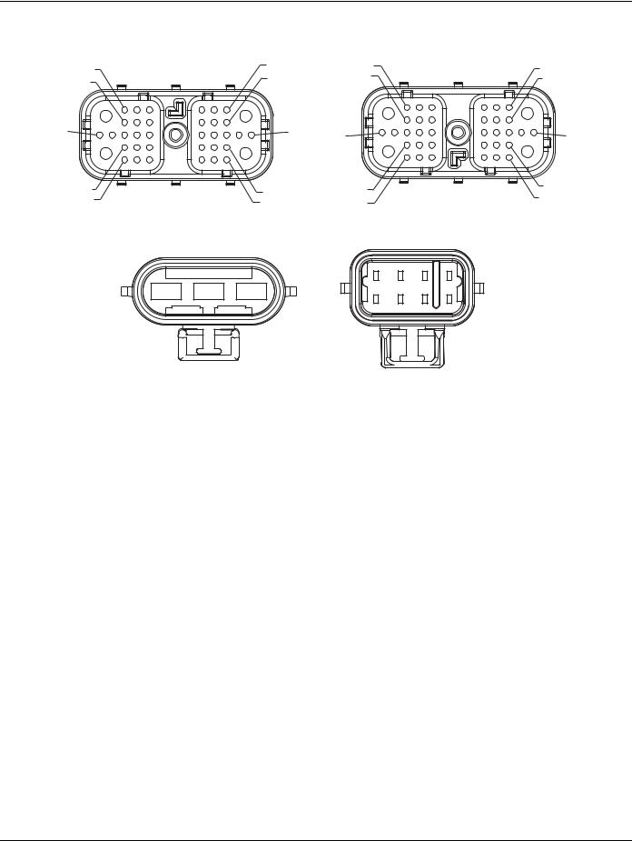
Component Identification
|
Front View |
|
|
|
|
Front View |
|
(TECU - Vehicle Interface Connector) |
1 |
|
29 |
(HCM - Vehicle Interface Connector) |
34 |
||
6 |
|
|
|||||
|
7 |
|
|
|
|||
12 |
|
|
23 |
|
|
28 |
|
|
|
|
|
|
|
||
36 |
35 |
|
|
|
37 |
38 |
|
22 |
|
|
13 |
13 |
|
|
22 |
|
|
|
|
|
|||
38 |
37 |
|
|
|
35 |
36 |
|
28 |
|
23 |
|
7 |
|
|
12 |
|
|
|
|
6 |
|||
34 |
|
29 |
|
1 |
|
|
|
|
|
|
|
|
|||
ECA -Pack 8-Way Connector
ECA - 3-Way Connector
C |
B |
A |
A |
B |
C |
D |
|
|
|
|
|||
|
|
|
H |
G |
F |
E |
NOTE: Refer to the Eaton Hybrid Component and Connector Location page for connector locations
TECU |
|
|
|
|
|
|
|
|
|
|
|
|
|
|
|
|
|
|
|
|
|
|
|
|
|
|
|
|
|
|
|
|
|
|
|
|
|
|
|
|
|
|
|
|
|
|
|
|
|
|
|
|
|
|
|
|
|
|
|
|
|
|
|
|
|
|
|
|
|
|
|
|
|
|
|
|
|
|
|
|
|
|
|
|
|
|
|
|
|
|
|
|
|
|
|
|
|
Battery |
|
|
|
|
|
|
|
|
|
|
|
|
|
|
|
|
|
|
|
|
|
|
|
|
|
|
|
|
|
|
|
|
|
TECU Power |
38 |
|
|
|
|
|
|
|
|
|
|
|
|
|
|
|
|
|
|
|
|
|
|
|
|
|
|
|
|
|
|
Neg (-) |
|
|
|
|
|
|
|
|
|
|
|
|
|
|
|
|
|
|
|
|
|
|
|
|
|
|
|
|
|
|
|||
TECU Ground |
36 |
|
|
|
|
|
|
|
|
|
|
|
|
|
|
|
|
|
|
|
|
|
|
|
|
|
|
|
|
|
|
|
|
|
|
|
|
|
|
|
|
|
|
|
|
|
|
|
|
|
|
|
|
|
|
|
|
|
|
|
|
|
|
|
|
TECU Ignition |
35 |
|
|
|
|
|
|
|
|
|
|
|
|
|
|
|
|
|
|
|
|
|
|
|
|
|
|
|
|
|
|
Plus (+) |
|
|
|
|
|
|
|
|
|
|
|
|
|
|
|
|
|
|
|
|
|
|
|
|
|
|
|
|
|
|
|||
|
|
|
|
|
|
|
|
|
|
|
|
|
|
|
|
|
|
|
|
|
|
|
|
|
|
|
|
|
|
|
|
|
|
|
|
|
|
|
|
|
|
|
|
|
|
|
|
|
|
|
|
|
|
|
|
|
|
|
|
|
|
|
|
|
|
|
|
|
|
|
|
|
|
|
|
|
|
|
|
|
Ignition Relay |
|
|
|
|
|
|
|
|
|
|
|
||||||
|
|
|
|
|
|
|
|
|
|
|
||||||||||||||||||||||
|
|
|
|
|
|
|
|
|
|
|
|
|
|
|
|
|
|
|
|
|
|
|
|
|
|
|
|
|
|
|
|
|
HCM |
|
|
|
|
87 |
|
|
|
|
|
|
|
|
|
|
|
|
|
|
|
|
|
|
|||||||||
|
|
|
|
|
|
|
|
|
|
|
|
|
|
|
|
|
|
|
|
|
|
|
|
|
|
|
|
|
|
|
|
|
HCM Ignition (Vehicle) |
|
|
|
|
|
|
|
|
|
|
|
|
|
|
|
|
|
|
|
|
|
|
|
|
|
|
|
|
|
ECA |
||
|
|
|
|
|
|
|
|
|
|
|
|
|
|
|
|
|
|
|
|
|
|
|
|
|
|
|
|
|
||||
|
|
|
|
|
|
|
|
|
|
|
|
|
|
|
|
|
|
|
|
|
|
|
|
|
|
|
|
|
|
|
||
35 |
|
|
|
|
|
|
|
|
|
|
|
|
|
|
|
|
|
|
|
|
|
|
|
|
ECA Power |
|||||||
|
|
|
|
|
|
|
|
|
|
|
|
|
|
|
|
|
|
|
|
|
|
|
|
|||||||||
HCM Ground (Vehicle) |
|
|
|
|
|
|
|
|
|
|
|
|
|
|
|
|
|
|
|
|
|
|
|
C |
|
|||||||
36 |
|
|
|
|
|
|
|
|
|
|
|
|
|
|
|
|
|
|
|
|
|
|
B |
|
ECA Ground |
|||||||
HCM Power (Vehicle) |
38 |
|
|
|
|
|
|
|
|
|
|
|
|
|
|
|
|
|
|
|
|
|
|
|
|
|
|
|
|
|
|
|
|
|
|
|
|
|
|
|
|
|
|
|
|
|
|
|
|
|
|
|
|
|
|
|
|
|
|
|
|
|
|||
Clutch Ignition (System) |
|
|
|
|
|
|
|
|
|
|
|
|
|
|
|
|
|
|
|
|
|
|
|
|
|
|
|
|
|
|
|
|
13 |
|
|
|
|
|
|
|
|
|
|
|
|
|
|
|
|
|
|
|
|
|
|
H |
|
|
|
|
|
|
|
||
|
|
|
|
|
|
|
|
|
|
|
|
|
|
|
|
|
|
|
|
|
|
|
|
|
|
|
|
|
||||
|
|
|
|
|
|
|
|
|
|
|
|
|
|
|
|
|
|
|
|
|
|
|
|
|
|
|
|
|
|
|
|
|
|
|
|
|
|
|
|
|
|
|
|
|
|
|
|
|
|
|
|
|
|
|
|
|
|
|
|
|
|
|
|
|
|
|
|
|
|
|
|
|
|
|
|
|
|
|
|
|
|
|
|
|
|
|
|
|
|
|
|
|
|
|
|
|
|
|
25 |
© 2015 Eaton. All rights reserved |
2015.10.20 |
 Loading...