


FS-6106A

Service Manual
Fuller Mid Range Transmissions
TRSM0170
October 2007

For parts or service call us
Pro Gear & Transmission, Inc.
1 (877) 776-4600
(407) 872-1901
parts@eprogear.com
906 W. Gore St.
Orlando, FL 32805

TABLE
OF
CONTENTS
FOREWORD. . . . . . . . . . . . . . . . . . . . . . . . . . . . . . . . . . . . . . . . . . . . . . . . . . . . . . . . . . . . . . . . . . . 2
MODEL
DESIGNATIONS AND SPECIFICATIONS . . . . . . . . . . . . . . . . . . . . . . . . . . . . . . . . . . . . 3
LUBRICATION . . . . . . . . . . . . . . . . . . . . . . . . . . . . . . . . . . . . . . . . . . . . . . . . . . . . . . . . . . . . . . . . . 4
OPERATION . . . . . . . . . . . . . . . . . . . . . . . . . . . . . . . . . . . . . . . . . . . . . . . . . . . . . . . . . . . . . . . . . . . 6
POWER FLOW. . . . . . . . . . . . . . . . . . . . . . . . . . . . . . . . . . . . . . . . . . . • . . . . . . . . . . . . . . . . . . . . . 7
TORQUE RECOMMENDATIONS . . . . . . . . . . . . . . . . . . . . . . . . . . . . . . . . . . . . . . . . . . . . . . . . . . 8
TOOL REFERENCE.. . . . . . . . . . . . . . . . . . . . . . . . . . . . . . . . . . . . . . . . . . . . . . . . . . . . . . . . . . . . 10
PREVENTIVE
MAINTENANCE....................................................
11
PRECAUTIONS
DISASSEMBLY.
. . . . . . . . . . . . . . . . . . . . . . . . . . . . . . . . . . . . . . . . . . . . . . . . . . . . . . . . . . . . 13
INSPECTION . . . . . . . . . . . . . . . . . . . . . . . . . . . . . . . . . . . . . . . . . . . . . . . . . . . . . . . . . . . . . . 13
REASSEMBLY . . . . . . . . . . . . . . . . . . . . . . . . . . . . . . . . . . . . . . . . . . . . . . . . . . . . . . . . . . . . . 15
DISASSEMBLY AND REASSEMBLY-SHIFTING CONTROLS
GEARSHIFT LEVER HOUSING
ASSEMBLY...
. . . . . . . . . . . . . . . . . . . . . . . . . . . . . . . . . .
16
SHIFT BAR HOUSING ASSEMBLY. . . . . . . . . . . . . . . . . . . . . . . . . . . . . . . . . . . . . . . . . . . . 19
REMOVAL-REAR
YOKE AND CLUTCH HOUSING . . . . . . . . . . . . . . . . . . . . . . . . . . . . . . . . . .
26
DISASSEMBLY-TRANSMISSION.................................................
28
REASSEMBLY-TRANSMISSION
..................................................
39
INSTALLATION-REAR YOKE AND CLUTCH HOUSING
..............................
54
INSTALLATION-SHIFTING CONTROLS
SHIFT BAR HOUSING
ASSEMBLY............................................
55
GEARSHIFT LEVER HOUSING ASSEMBLY
.....................................
56
OPTIONS . . . . . . . . . . . . . . . . . . . . . . . . . . . . . . . . . . . . . . . . . . . . . . . . . . . . . . . . . . . . . . . . . . . . .
57
1
FOREWORD
This manual is designed
to
provide detailed informa-
tion necessary
to
service and repair the Fuller®
Transmission listed on the cover.
As
outlined in the Table
of
Contents, the manual is
divided into 3 main sections:
a.
Technical information and reference
b.
Removal, disassembly, reassembly and
installation
c.
Options
The format
of
the manual is designed
to
be
followed in
its
entirety
if
complete disassembly and
reassembly
of
the transmission is necessary. But
if
only one component
of
the transmission needs to be
repaired, refer to the
Table
of
Contents
for
the page
numbers showing that component. For
example,
if
you need
to
work
on the
Shift
Bar Housing, you
will
find
instructions
for
removal, disassembly and reas-
sembly
on page
19.
Instructions
for
installation are
on page
55.
Service Manuals, Illustrated Parts Lists,
Drivers
Instructions, and other
forms
of product
service information
for
these and other Fuller Trans-
missions are
available upon request. A Technical
Literature Order Form may be found in the back
of
this manual*.
You
may also obtain Service Bulletins,
detailing
information on product improvements,
re-
pair procedures and other service-related subjects by
writing
to
the following address:
EATON
CORPORATION
TRANSMISSION DIVISION
Technical Service
Department
P.O.
Box
4013
Kalamazoo, Michigan 49003
(616)
342-3344
Every
effort
has
been
made
to
ensure
the
accuracy
of
all
information
in
this
brochure.
However,
Eaton
Transmission
Division
makes
no
expressed
or
implied
warranty
or
representation
based
on
the
enclosed
information.
Any
errors
or
omissions
may
be
reported
to
Training
and
Publications,
Eaton
Transmission
Division,
P.O.
Box
4013,
Kalamazoo,
Ml
49003.
2
MODEL
DESIGNATIONS
AND
SPECIFICATIONS
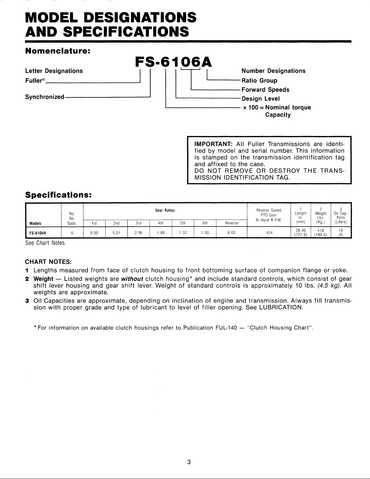
Nomenclature:
FS-6106A
~:~::~D-es_i_g_n_a_ti_o_n_s
_______
_.I
I 1
·1
-
_·_1
____
~~:
0
b;r:::ignations
_ -
Forward
Speeds
Synchronized----------~
'----------Design
Level
Specifications:
No.
No.
Models
Spds.
1st
2nd
3rd
FS-6106A
6
9.00
5.01
2.96
See
Chart
Notes.
CHART NOTES:
..____
_________
x
100
=Nominal torque
Gear
Ratios
4th
5th
1.89
1.32
Capacity
IMPORTANT: All Fuller Transmissions are identi-
fied by
model and serial number. This information
is stamped on the transmission
identification
tag
and affixed
to
the case.
DO
NOT
REMOVE
OR
DESTROY THE TRANS-
MISSION IDENTIFICATION
TAG.
Relative
Speed
1
2 3
PTO
Gear
Length
Weight
Oil
Cap.
To
Input
A.PM.
In.
Lbs.
Pints
6th
Reverse
(mm)
(Kg.)
(Liters)
1.00
8.00
.454
28.46
418
19
(722.9)
(189.6)
(9)
1 Lengths measured
from
face
of
clutch
housing
to
front
bottoming
surface
of
companion flange
or
yoke.
2
Weight
- Listed
weights
are without
clutch
housing*
and include standard controls,
which
consist
of
gear
shift
lever housing and gear
shift
lever. Weight
of
standard
controls
is approximately 10 lbs. (4.5
kg)_
All
weights are approximate.
3
Oil Capacities are approximate, depending on inclination
of
engine and transmission. Always
fill
transmis-
sion
with
proper grade and type
of
lubricant
to
level
of
filler
opening. See LUBRICATION.
*For
information
on available
clutch
housings refer
to
Publication FUL-140 -
"Clutch
Housing
Chart".
3
LUBRICATION
Proper Lubrication ...
the
Key
to long
transmission life
Proper lubrication procedures are the key
to
a good
all-around maintenance program. If the oil is not doing
its
job,
or
if
the
oil
level
is
ignored, all the main-
tenance procedures in the
world are not going
to
keep
the transmission running
or
assure long transmission
life.
Fuller®
Transmissions are designed so that the in-
ternal parts operate in a bath
of
oil circulated by the
motion
of
gears and shafts. Grey iron parts have built-
in channels where needed, to help lubricate bearings
and shafts.
Thus,
all parts will be amply lubricated
if
these pro-
cedures are
closely followed:
1.
Maintain oil level. Inspect regularly.
2.
Change oil regularly.
3.
Use
the correct grade and type
of
oil.
4.
Buy from a reputable dealer.
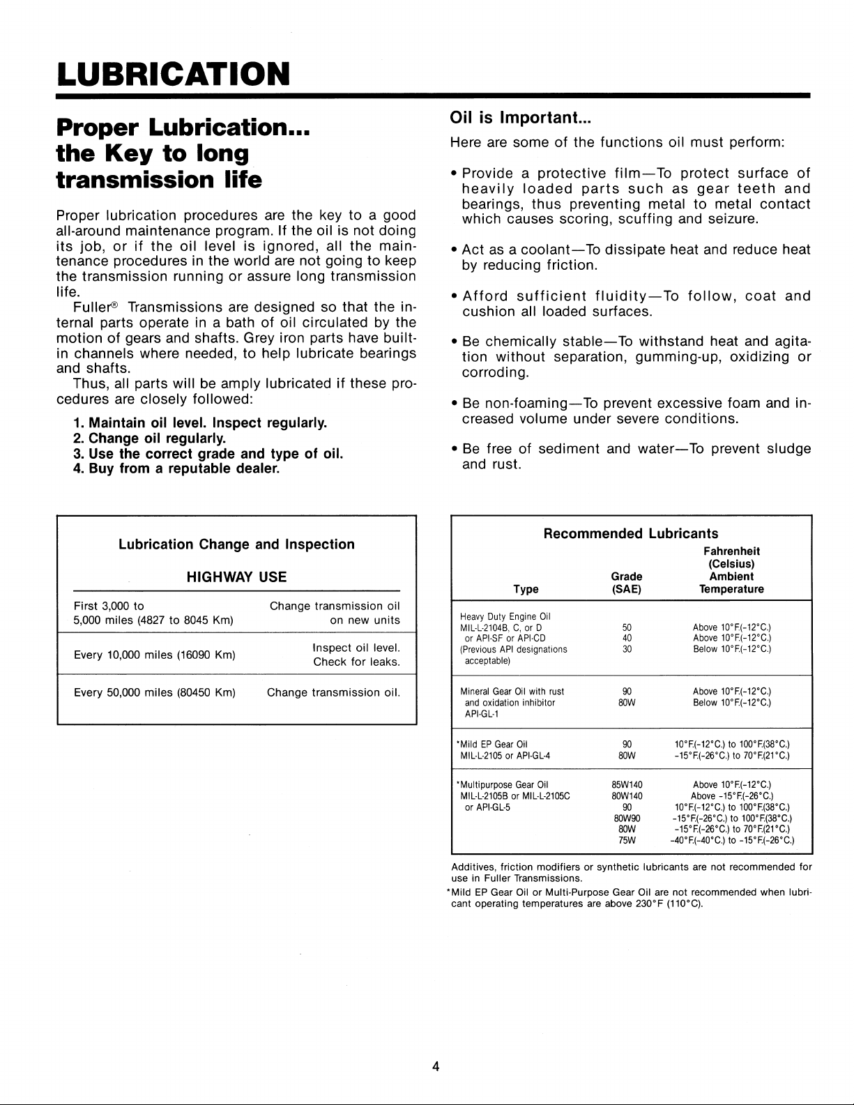
Lubrication Change and Inspection
HIGHWAY
USE
First
3,000
to
Change transmission oil
5,000
miles
(4827
to
8045
Km)
on new units
Every
10,000
miles
(16090
Km)
Inspect oil level.
Check for leaks.
Every
50,000
miles
(80450
Km)
Change transmission oil.
4
Oil
is
Important.
..
Here are some
of
the functions oil must perform:
• Provide a
protective
film-
To
protect
surface
of
heavily
loaded
parts
such
as
gear
teeth
and
bearings,
thus
preventing metal
to
metal
contact
which causes scoring,
scuffing
and seizure.
•Act
as a
coolant-
To
dissipate heat and reduce heat
by reducing friction.
•Afford
sufficient
fluidity-
To
follow,
coat
and
cushion
all loaded surfaces.
•
Be
chemically
stable-
To
withstand heat and agita-
tion
without
separation, gumming-up, oxidizing
or
corroding.
•
Be
non-foaming-
To
prevent excessive foam and in-
creased
volume under severe conditions.
•
Be
free of sediment and
water-
To
prevent sludge
and rust.
Recommended Lubricants
Fahrenheit
(Celsius)
Grade Ambient
Type
(SAE)
Temperature
Heavy
Duty
Engine
Oil
MIL·L·2104B,
C,
or
D
50
Above
10'F.(-12'C.)
or
APl-SF
or
APl-CD
40
Above
10'F.(-12'C.)
(Previous
API
designations
30
Below
10'F.(-12'C.)
acceptable)
Mineral
Gear
Oil
with
rust
90
Above
10'F.(-12'C.)
and
oxidation
inhibitor
BOW
Below
10'F.(-12'C.)
APl-GL-1
'Mild
EP
Gear
Oil
90
10'F.(-12'C.)
to
100'F.(38'C.)
MIL-L-2105
or
APl·GL-4
BOW
-15'F.(-26'C.)
to
70'F.(21'C.)
'Multipurpose
Gear
Oil
85W140
Above
10'
F.(-12'C.)
MIL-L-2105B
or
MIL-L-2105C
80W140
Above
-15'F.(-26'C.)
or
APl-GL-5
90
10'F.(-12'C.)
to
100'F.(38'C.)
80W90
-15'F.(-26'C.)
to
100'
F.(38'C.)
sow
-15'F.(-26'C.)
to
70'F.(21'C.)
75W
-40'F.(-40'C.)
to
-15'F.(-26'C.)
Additives, friction modifiers
or
synthetic lubricants are not recommended
for
use in Fuller Transmissions.
'Mild
EP
Gear Oil
or
Multi-Purpose Gear Oil are not recommended when lubri-
cant operating temperatures are above
230'
F (110'C).

LUBRICATION
Proper
Oil
Level
Make sure oil is level with
filler
opening. Because you can reach oil with your finger does not mean oil is at proper
level. One inch
of
oil level
is
about one gallon
of
oil. The FS-6106 is equipped with a
dip
stick
which may also be
used to check
oil level.
Draining
Oil
Drain transmission while oil is warm.
To
drain oil remove the drain plug at
bottom
of
case. Clean the drain plug
before re-installing.
Refilling
Clean case around filler plug and remove plug from side
of
case. Fill transmission to the level
of
the
filler
opening.
The exact amount
of
oil will depend on the transmission inclination and model. In every instance,
fill
to the
level
of
the
filler
opening.
Do
not over
fill-this
will cause oil to
be
forced out
of
the case through front bearing cover.
When adding
oil, types and brands
of
oil should not
be
intermixed because of possible incompatibility.
Operating
Temperatures
The transmission should not be operated
consistently
at temperatures above 250°F (120°C). However,
intermittent
operating temperatures to 300°F (149°C) will not harm the transmission. Operating temperatures above 250°F in-
crease the lubricant's rate
of
oxidation and shorten
its
effective life. When the transmission is operated intermit-
tently above 250°, heavy
duty
engine oil provides the best oxidation resistance. When the average operating
temperature is above
250°F, the transmission may require more frequent oil changes
or
external cooling.
The following
conditions
in any combination can cause operating temperatures
of
over 250°F:
(1)
operating con-
sistently at
slow
speeds,
(2)
high ambient temperatures,
(3)
restricted air
flow
around transmission,
(4)
exhaust
system too
close to transmission,
(5)
high horsepower, overdrive operation.
5

OPERATION
Gear
Shift
Lever
Pattern
and
Shifting
Instructions
Follow the simple 6-speed
shift
pattern
...
,..
"II
,.
1
.....
.Ill
..
,..
"
,..
.,
,..
R 2
..
...
....
.Ill
..
General
Information
FS-6106A transmissions have six forward speeds and
one reverse, and
are
shifted
as
you would shift any
synchronized
manual transmission, following the sim-
ple 6-speed shift pattern.
Driving
Tips
• Always use the
clutch
when making
upshifts
or
downshifts. Premature synchronizer
failure can
re-
sult from not using the clutch.
• Always select
a starting gear that will provide suffi-
cient reduction for the
load and terrain.
• Never downshift at
too
high
of
a road speed.
• Never slam or jerk the
shift
lever to complete gear
engagement.
• Never coast with the transmission in neutral and
the
clutch dis-engaged.
6
3
4
..,
"'II
5
....
.....
.Ill
"
N
-
.,
,..
"'II
6
..ii
....
.Ill
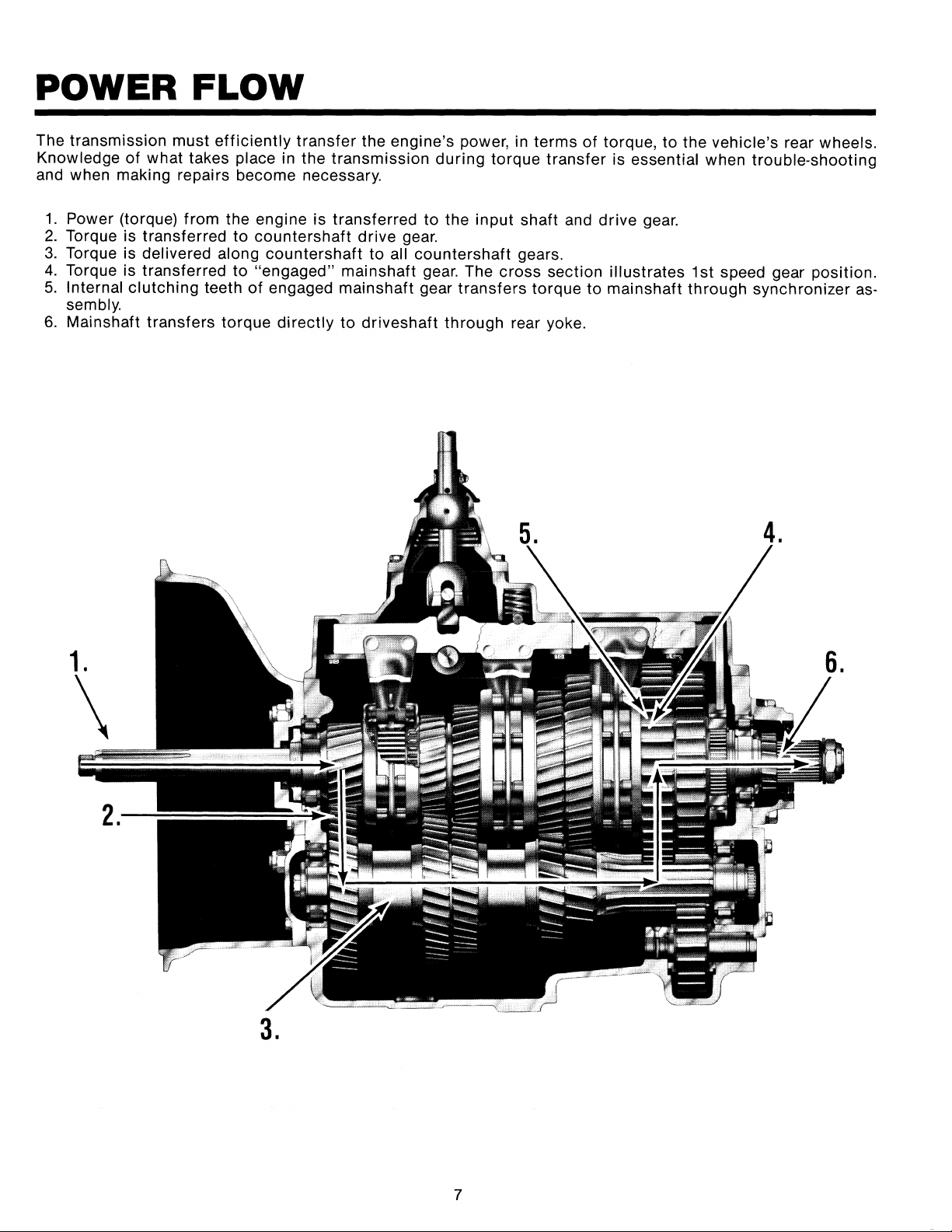
POWER
FLOW
The transmission must
efficiently
transfer
the engine's power, in terms
of
torque, to the vehicle's rear wheels.
Knowledge
of
what takes place in the transmission
during
torque
transfer
is essential when trouble-shooting
and when making repairs become necessary.
1.
Power (torque) from the engine is transferred to the
input
shaft and drive gear.
2.
Torque is transferred
to
countershaft drive gear.
3.
Torque is delivered along countershaft to all countershaft gears.
4.
Torque is transferred
to
"engaged" mainshaft gear. The cross section illustrates 1st speed gear position.
5.
Internal
clutching
teeth
of
engaged mainshaft gear
transfers
torque
to
mainshaft through synchronizer
as-
sembly.
6.
Mainshaft transfers torque
directly
to
driveshaft through rear yoke.
1.
\
3.
7
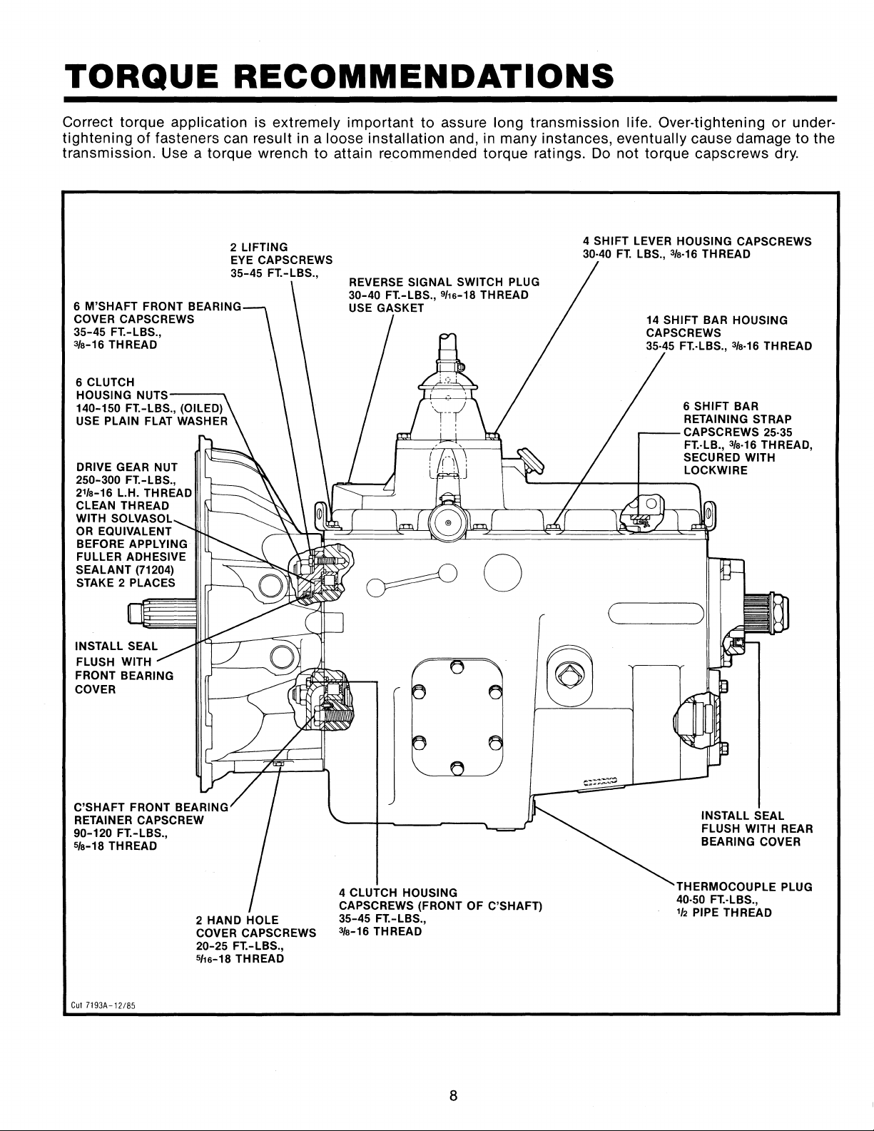
TORQUE
RECOMMENDATIONS
Correct torque application is extremely
important
to
assure long transmission life. Over-tightening
or
under-
tightening
of
fasteners can result in a loose installation and, in many instances, eventually cause damage
to
the
transmission.
Use a torque wrench
to
attain recommended torque ratings. Do
not
torque capscrews dry.
2 LIFTING
EYE
CAPSCREWS
35-45
FT.-LBS.,
6
M'SHAFT FRONT BEARING
COVER CAPSCREWS
35-45
FT.-LBS.,
3/s-16 THREAD
6
CLUTCH
HOUSING
NUTS--~
140-150
FT.-LBS., (OILED)
USE PLAIN
FLAT WASHER
DRIVE GEAR NUT
250-300
FT.-LBS.,
21/s-16 L.H. THREAD
CLEAN THREAD
WITH SOLVASOL
OR
EQUIVALENT
BEFORE APPLYING
FULLER ADHESIVE
SEALANT
(71204)
STAKE 2 PLACES
INSTALL SEAL
FLUSH WITH
FRONT BEARING
COVER
C'SHAFT FRONT BEARING
RETAINER
CAPSCREW
90-120
FT.-LBS.,
5/a-18 THREAD
Cut
7193A-12185
2 HAND HOLE
COVER CAPSCREWS
20-25
FT.-LBS.,
S/1s-18 THREAD
REVERSE SIGNAL SWITCH PLUG
30-40
FT.-LBS., 9f1s-18 THREAD
USE GASKET
4 CLUTCH HOUSING
CAPSCREWS
(FRONT OF C'SHAFT)
35-45
FT.-LBS.,
3/s-16 THREAD
8
4 SHIFT LEVER HOUSING CAPSCREWS
30·40
FT.
LBS.,
3/s-16
THREAD
14 SHIFT BAR HOUSING
CAPSCREWS
35.45 FT.·LBS.,
3/s-16
THREAD
6
SHIFT BAR
RETAINING STRAP
.----CAPSCREWS
25-35
FT.·LB.,
3/s-16
THREAD,
SECURED WITH
LOCKWIRE
INSTALL SEAL
FLUSH WITH
REAR
BEARING COVER
THERMOCOUPLE PLUG
40-50 FT.·LBS.,
1h
PIPE THREAD
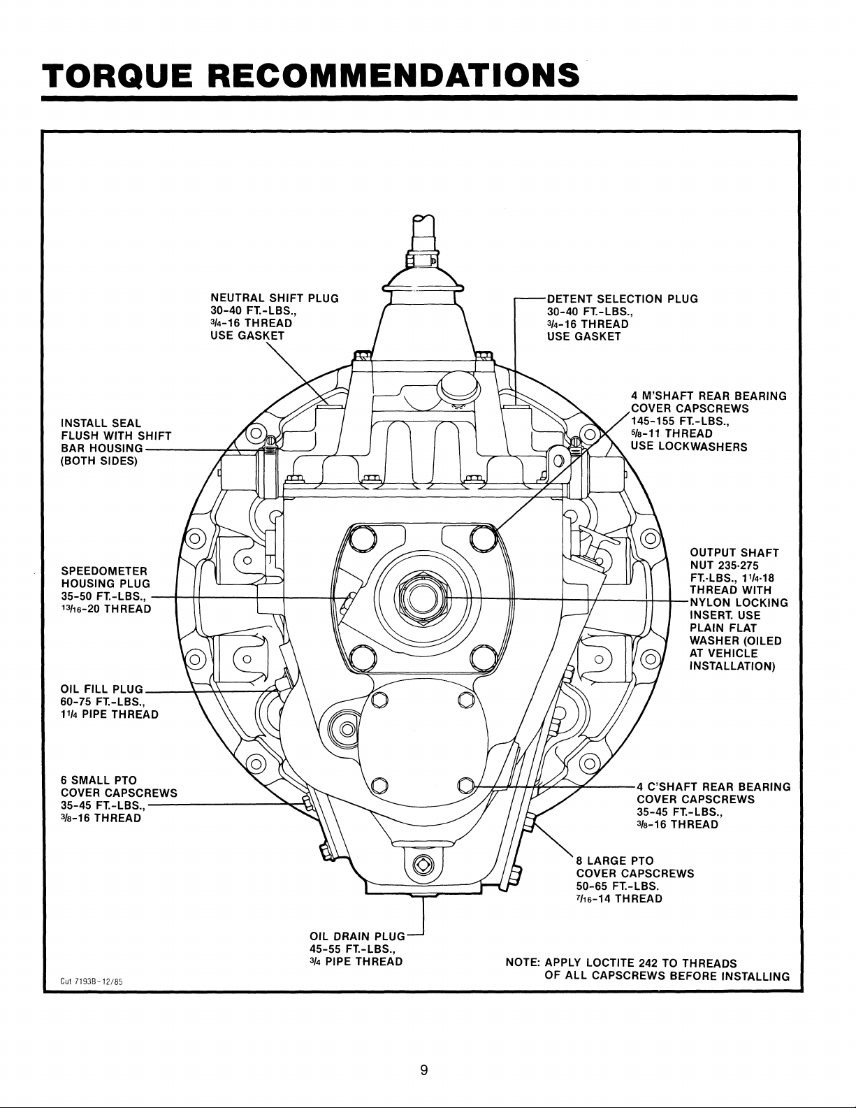
TORQUE
RECOMMENDATIONS
INSTALL SEAL
FLUSH WITH SHIFT
NEUTRAL SHIFT PLUG
30-40
FT.-LBS.,
3/4-16 THREAD
USE GASKET
BAR HOUSING
-----;.~=ll~f--:::~_.,.J~_)
(BOTH SIDES)
SPEEDOMETER
HOUSING PLUG
35-50
FT.-LBS.,
--+---H----1--+---.11--~
13/15-20
THREAD
OIL FILL PLUG
__
__:~..:..+--......4~
60-75
FT.-LBS.,
11/4
PIPE
THREAD
6
SMALL
PTO
COVER CAPSCREWS
35-45
FT.-LBS.,
---------::lo.,,o-4:'>.\
3/a-16 THREAD
Cut
71938-12/85
OIL DRAIN PLUG
45-55
FT.-LBS.,
3/4
PIPE THREAD
9
DETENT SELECTION PLUG
30-40
FT.-LBS.,
3/4-16 THREAD
USE GASKET
4
M'SHAFT
REAR BEARING
COVER CAPSCREWS
145-155
FT.-LBS.,
s/a-11 THREAD
USE LOCKWASHERS
OUTPUT SHAFT
NUT
235-275
FT.·LBS.,
11/4·18
THREAD WITH
lltt---tt-t----ttt----+--t-+-----4-l-.l--NvLoN
LOCKING
INSERT. USE
PLAIN
FLAT
WASHER (OILED
AT
VEHICLE
INSTALLATION)
-~-+--:1'-1--+-,~"""--""~--4
C'SHAFT
REAR BEARING
COVER CAPSCREWS
35-45
FT.-LBS.,
3/a-16 THREAD
8 LARGE
PTO
COVER CAPSCREWS
50-65
FT.-LBS.
7'1s-14
TH
READ
NOTE: APPLY LOCTITE 242
TO
THREADS
OF
ALL
CAPSCREWS BEFORE INSTALLING

TOOL
REFERENCE
Some repair procedures pictured in
this
manual show
the use
of
specialized tools. Their actual use is rec-
ommended
as
they make transmission repair easier,
faster, and prevent
costly damage
to
critical parts.
But for the most part, ordinary mechanic's
tools
such as
socket
wrenches, screwdrivers, etc., and
other standard shop items such as a press,
mauls and
soft bars
are
all that is needed to successfully disas-
semble and reassemble any Fuller Transmission.
PAGE
TOOL
18
Tension Spring Driver
35
Snap Ring Pliers
The specialized
tools
listed below can be obtained
from a
tool supplier
or
made from dimensions as
re-
quired by the individual user. Detailed Fuller Transmis-
sion
Tool Prints are available upon request by writing.
Eaton Corporation
Transmission Division
Technical Service Dept.
P.O.
Box 4013
Kalamazoo,
Michigan 49003
HOW OBTAINED
Made from Fuller Transmission
Print T-11938
Tool Supplier
38
Impact Puller
(1/2·13
Threaded End)
Tool Supplier
42
Countershaft Support Tool Made from Fuller Transmission
and Bearing Driver
Print
T·22913·C
50
Bearing Guide
Made from
Fuller Transmission
Print
T-18042·110
51
Oil Seal Driver, Rear Bearing Cover
Made from
Fuller Transmission
Print
T-18088·61
52
Input Shaft
Nut
Installer
Made from Fuller Transmission
Print T
·22553-A
52
Torque Wrench, 1000 Lbs./Ft. Capacity
Tool Supplier
53
Oil Seal Driver Made from Fuller Transmission
Front Bearing Cover (push type
clutch)
Print T-18088·67
53
Oil Seal Driver Made from Fuller Transmission
Front Bearing Cover
(pull type clutch)
Print T-18088·64
10
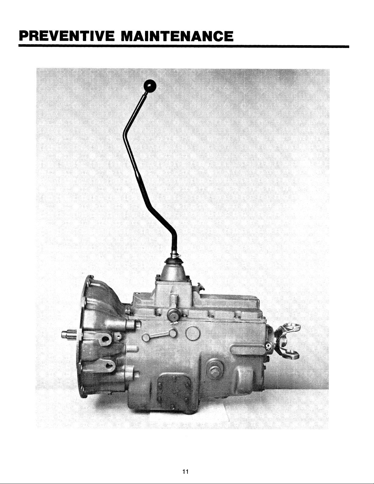
PREVENTIVE
MAINTENANCE
11

PREVENTIVE
MAINTENANCE
PREVENTIVE
MAINTENANCE
CHECK
CHART
CHECKS
WITHOUT
PARTIAL
DISASSEMBLY
OF
CHASSIS
OR
CAB
1.
Clutch Housing Mounting
a.
Check all capscrews in bolt circle
of
clutch
housing
for
looseness.
2.
Clutch Release Bearing (Not Shown)
a.
Remove hand hole cover and check radial
and axial clearance in release bearing.
b.
Check relative position
of
thrust surface
of
release bearing with thrust sleeve on push-
type
clutches.
3.
Clutch Pedal Shaft and Bores
a.
Pry upward on shafts to check
wear.
b.
If
excessive movement is found, remove
clutch release mechanism and check bush-
ings in bores and wear on shafts.
4.
Lubricant
a.
Change at specified service intervals.
b.
Use only the types and grades as recom-
mended.
See
LUBRICATION.
5.
Filler
and
Drain Plugs
a.
Remove
filler
plug
or
dip
stick
and check
level
of
lubricant
at
specified
intervals.
Tighten
filler
and drain plugs securely.
6.
Capscrews
and
Gaskets
a.
Check all capscrews, especially those on
PTO covers and rear bearing covers
for
looseness which would cause oil leakage.
See
TORQUE RECOMMENDATIONS.
b.
Check
PTO
opening and rear bearing covers
for
oil leakage due
to
faulty gasket.
7.
Gear Shift Lever
a.
Check
for
looseness and free play in hous-
ing.
If
lever is loose in housing, proceed
with Check No.
8.
12
8.
Gear Shift Lever Housing Assembly
a.
Remove the gear
shift
lever
housing
as-
sembly from transmission.
b.
Check tension spring and washer
for
set
and wear.
c.
Check
bottom
end
of
gear
shift
lever
for
wear
of
slots. Also check
for
wear
of
finger
assembly.
CHECKS
WITH
DRIVE
LINE
DROPPED
9.
Universal Joint Companion Flange
or
Yoke
Nut
a.
Check
for
tightness.
Tighten
to
recom-
mended torque.
10. Output Shaft (Not Shown)
a.
Pry upward against output shaft to check
radial clearance in mainshaft rear bearing.
CHECKS
WITH
UNIVERSAL
JOINT
COMPANION
FLANGE
OR
YOKE
REMOVED
NOTE:
If
necessary, use
solvent
and
shop
rag
to
clean sealing surface
of
companion flange
or
yoke.
DO
NOT
USE
CROCUS CLOTH, EMERY
PAPER
OR
OTHER ABRASIVE MATERIALS
THAT WILL MAR SURFACE FINISH.
11. Splines
on
Output Shaft
(Not Shown)
a.
Check
for
wear from movement and chuck-
ing action
of
the universal
joint
companion
flange
or
yoke.
12.
Mainshaft Rear Bearing Cover
a.
Check oil seal
for
wear.

PRECAUTIONS
Disassembly
It is assumed in the detailed assembly
instructions
that the lubricant has been drained from transmission, the
necessary
linkage
disconnected
and the transmission has been removed from vehicle chassis. Removal
of
the
gear
shift
lever housing assembly (or remote control assembly) is included in the detailed
instructions
(Disas-
sembly
and
Reassembly-Shifting
Controls); however,
this
assembly
must
be detached from
shift
bar housing
before transmission can be removed.
FOLLOW CLOSELY EACH PROCEDURE IN THE DETAILED INSTRUCTIONS, MAKING USE OF THE
TEXT,
ILLUS-
TRATIONS
AND PHOTOGRAPHS PROVIDED.
1.
BEARINGS-Carefully
wash and
relubricate
all
reusable
bearings
as removed and
protectively
wrap until ready
for
use. Remove bearings planned
to
be reused
with
pullers designed
for
this
pur-
pose.
2.
ASSEMBLIES-When
disassembling
the various
assemblies, such as the mainshaft, countershafts,
and
shift
bar
housing,
lay all
parts
on a clean
bench in the same sequence as removed. This pro-
cedure
will
simplify
reassembly and reduce the
possibility
of
losing parts.
3.
SNAP
RINGS-Remove
snap rings with pliers de-
signed for this purpose. Snap rings removed in this
manner can
be
reused,
if
they are not sprung
or
loose.
Inspection
4.
CLEANLINESS-Provide a clean place to work. It is
important that no dirt
or
foreign material enters the
unit during repairs. Dirt is
an
abrasive and can dam-
age bearings. It is always good practice
to
clean the
outside of the unit before starting the
planned disas-
sembly.
6.
WHEN USING TOOLS
TO
MOVE
PARTS-Always
ap-
ply force
to
shafts, housings, etc,
with
restraint.
Movement of some parts is restricted. Never
apply
force to the part being driven after it stops solidly.
The use of soft hammers, bars and mauls for all dis-
assembly
work is recommended.
Before
reassembling the transmission, check each part carefully for abnormal
or
excessive wear and damage to de-
termine reuse or replacement. When replacement is necessary, use only genuine Fuller Transmission parts to assure
continued performance and extended
life from your unit.
Since the cost
of
a new part is generally a small fraction of the total cost of downtime and labor, avoid reusing a
questionable part which could lead to additional repairs and expense soon after initial reassembly.
To
aid in deter-
mining the reuse
or
replacement
of
any transmission part, consideration should also
be
given
to
the unit's history,
mileage, application, etc.
Recommended inspection procedures are provided in the
following checklist.
A.
BEARINGS
1.
Wash all bearings in clean solvent. Check balls,
rollers
and raceways for pitting, discoloration,
and
spalled areas. Replace bearings that
are
pitted, discolored, spalled,
or
damaged during
disassembly.
2.
Lubricate bearings that
are
not pitted, discol-
ored,
or
spalled and check for axial and radial
clearances.
3.
Replace bearings with excessive clearances.
4.
Check bearing fits. Bearing inner races should
be
tight
to
shaft; outer races slightly tight
to
slightly loose in case bore. If bearing spins
freely in bore, however, case should be
re-
placed.
13
B.
GEARS
1.
Check gear teeth
for
frosting and pitting. Frost-
ing
of
gear tooth faces present no threat
of
transmission failure. Often in continued opera-
tion
of
the unit, frosted gears will "heal" and
not progress
to
the pitting stage. And in most
cases, gears with
light to moderate pitted teeth
have
considerable gear life remaining and can
be
reused. But gears with advanced stage pit-
ting should be replaced.
2.
Check
for
gears
with
clutching
teeth abnor-
mally
worn, tapered,
or
reduced in length from
clashing in shifting. Replace gears found in any
of
these conditions.
PRECAUTIONS
Inspection
(cont'd.)
3.
Check axial clearance
of
gears. Where exces-
sive
clearance is found, check gear snap ring,
split washer, clutch hub, and gear hub for
ex-
cessive
wear.
C.
SPLINES
1. Check splines on all shafts for abnormal
wear.
If sliding clutch gears, companion flange,
or
clutch
hub have worn
into
the sides
of
the
splines, replace the specific shaft affected.
D.
SPLIT WASHERS
1.
Check surfaces of all washers. Washers scored
or
reduced in thickness should
be
replaced.
E.
REVERSE IDLER GEAR ASSEMBLIES
1.
Check for excessive wear from action of roller
bearings.
F.
GRAY IRON PARTS
1.
Check all gray iron parts for cracks
and
breaks.
Replace
or
repair parts found to be damaged.
Heavy castings may be
welded
or
brazed pro-
vided the cracks do not extend into bearing
bores or
bolting surfaces. When welding, how-
ever,
never place the ground so
as
to allow cur-
rent to pass through the transmission.
G. CLUTCH RELEASE PARTS
1.
Check
clutch
release parts. Replace yokes
worn
at cam
surfaces
and
bearing
carrier
worn at contact pads.
2.
Check pedal shafts. Replace those worn at
bushing surfaces.
H.
SHIFT
BAR
HOUSING
ASSEMBLY
1. Check
for
wear on
shift
yokes and finger as-
sembly at pads and lever slot. Replace exces-
sively worn parts.
2.
Check yokes
for
correct alignment. Replace
sprung yokes.
3.
Check lockscrews in yokes assembly retainer
plates. Tighten and rewire those found loose.
14
I.
GEAR
SHIFT
LEVER
HOUSING
ASSEMBLY
1.
Check spring tension on
shift
lever. Replace
tension spring
if
lever moves
too
freely.
2.
If
housing
is
disassembled,
check
bottom
end
of
gear
shift
lever and
shift
finger
as-
sembly
for
wear. Replace both parts
if
exces-
sively worn.
J. BEARING COVERS
1. Check covers
for
wear from
thrust
of
adjacent
bearing.
Replace covers damaged from
thrust
of
bearing
outer
race.
2.
Check
bores
of
covers
for
wear.
Replace
those worn oversize.
K.
OIL SEALS
1. Check oil seal in
input
shaft and rear bearing
cover.
If sealing
action
of
lip
has been de-
stroyed,
replace seal.
L.
CLUTCHING
TEETH
1. Check all
shift
yokes and yoke
slots
in sliding
clutches
for
extreme wear
or
discoloration
from heat.
2.
Check engaging teeth
for
partial engagement
pattern.
M.
SYNCHRONIZER
ASSEMBLY
1. Check synchronizer
for
burrs, uneven and ex-
cessive wear at
contact
surface, and metal
particles.
2.
Check
blocker
pins
for
excessive
wear
or
looseness.
3.
Check synchronizer
contact
surfaces on the
synchronizer cups
for
wear.
N.
0-RINGS
1. Check
0-ring
of
idler
shaft
for
cracks
or
cuts.

PRECAUTIONS
Reassembly
Make sure that interiors
of
case and housings are clean. It is
important
that
dirt
and
other
foreign materials be
kept
out
of the transmission during reassembly. Dirt is
an
abrasive and can damage polished surfaces
of
bearings and washers. Use certain precautions, as listed below, during reassembly.
1.
GASKETS-Use
new
gaskets
throughout
the
6.
AXIAL
CLEARANCES-Maintain
original
axial
transmission as
it
is
being rebuilt. Make sure all clearances
for
mainshaft gears.
gaskets are
_inst~lled.
An
omissio~
of. any gasket
7.
BEARINGS-Use
of
flanged-end bearing drivers is
can
_result
in
011
leakage
or
misalignment
of
recommended
for
the
installation
of
bearings.
bearing covers. These drivers apply equal force
to
both bearing
2.
CAPSCREWS-To
prevent oil leakage, use
Loctite
races,
preventing
damage
to
rollers
and races
242
thread sealant on all capscrews.
For
torque while maintaining correct bearing alignment
with
ratings, see TORQUE RECOMMENDATIONS. bore and shaft. Avoid using a
tubular
or
sleeve-
3.
O·RINGS-Lubricate
0-rings
with
silicone
lubri-
cant.
4.
ASSEMBLY-Refer
to
the
illustrations
provided in
the
detailed disassembly
instructions
as a guide
to
reassembly.
5.
INITIAL
LUBRICATION-Coat
all
thrust
washers
and
synchronizers
with
transmission
lubricant
during reassembly
to
prevent scoring and galling
of
such parts.
type driver, whenever
possible, as force is applied
to
only
one
of
the bearing races. See TOOL REF-
ERENCE.
8.
UNIVERSAL
JOINT
COMPANION
FLANGE
OR
YOKE-Pull
the
companion
flange
or
yoke
into
place
with
the
output
shaft
nut,
using
235-275
foot-pounds
of
torque. Make sure the speedome-
ter
drive gear
or
a replacement spacer has been in-
stalled.
Failure
to
properly
torque
the
nut
can
result in damage
to
the mainshaft rear bearing.
IMPORTANT: REFER
TO
THE APPROPRIATE ILLUSTRATED
PARTS
LIST (SPECI·
FIED
BY
MODEL SERIES)
TO
ENSURE THAT PROPER
PARTS
ARE
USED DURING REASSEMBLY OF THE TRANSMISSION.
15

DISASSEMBLY
AND
REASSEMBLY
SHIFTING
CONTROLS
GEARSHIFT LEVER HOUSING ASSEMBLY
LEVER
HOUSING
ASSEMBLY
LEVER
""'U
~CLAMP
SHIFT
LEVER-....-...
HOUSING
GASKET
"O"RING~
Cut
6291-12/85
-~-~
A.
Removal
and
Disassembly
16-01
1.
Turn
out four capscrews and remove tower as·
sembly
from shift bar housing.
16
SHIFT
LEVER
SPRING
,
iOLL
PIN
i1---~
__
SHIFT
LEVER
LOCKWASHER
STUD
RISER
BLOCK
GASKET
16-02
2.
Remove boot and
shift
ball from gearshift lever
and secure assembly in vise with bottom
of
hous-
ing up. Use a large screwdriver to twist between
spring and housing, forcing spring from under
lugs
in
housing.
Do
one coil
at
a time.
DISASSEMBLY
AND
REASSEMBLY
SHIFTING
CONTROLS
GEARSHIFT LEVER HOUSING ASSEMBLY (con't.)
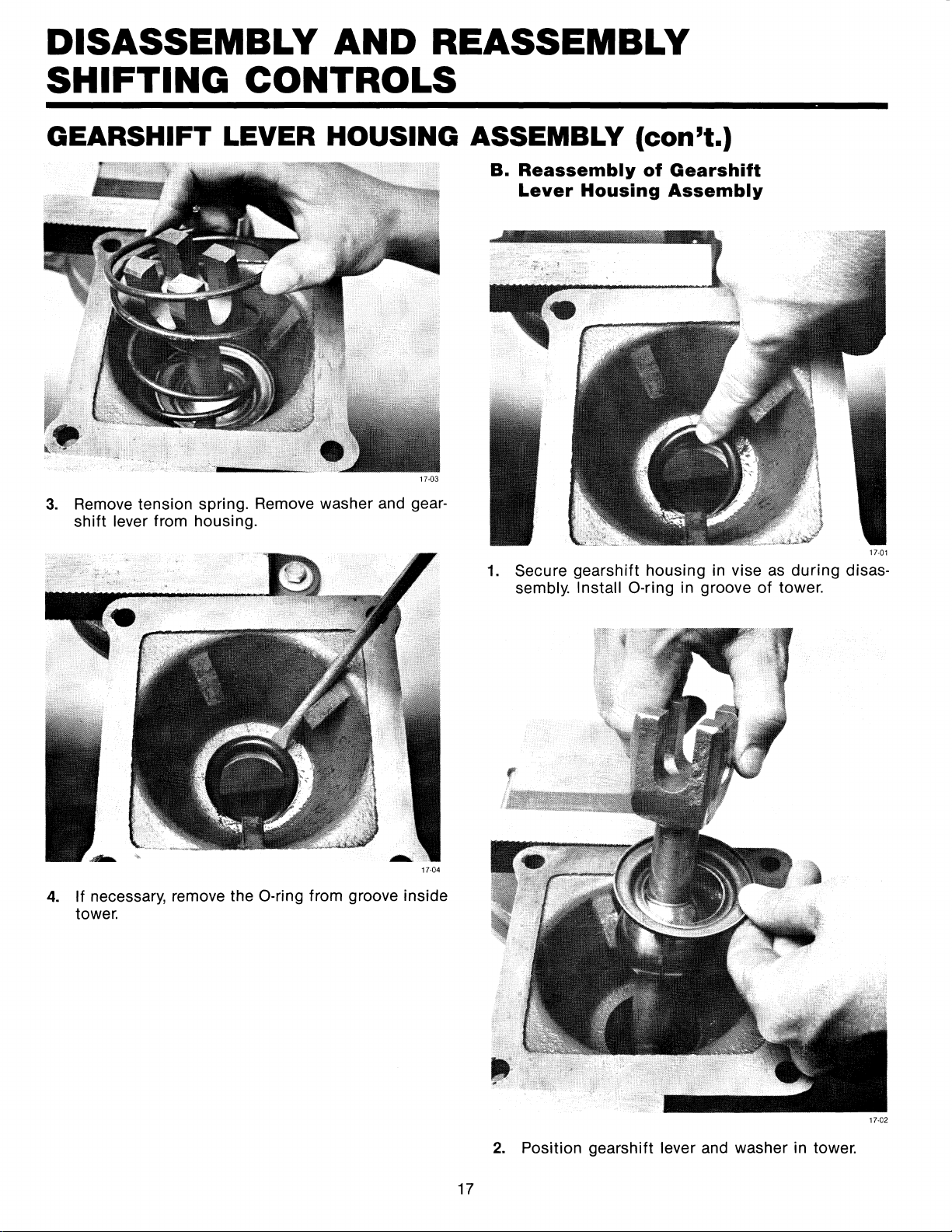
17-03
3.
Remove tension spring. Remove washer and gear-
shift
lever from housing.
B.
Reassembly
of
Gearshift
Lever
Housing
Assembly
17-01
1.
Secure gearshift housing in vise as during disas-
sembly. Install
0-ring
in groove of tower.
17-04
4.
If necessary, remove the 0-ring from groove inside
tower.
17
17-02
2.
Position gearshift lever and washer in tower.
 Loading...