


Service Manual
Fuller Heavy Duty Transmissions
TRSM0250
October 2007

For parts or service call us Pro Gear & Transmission, Inc.
1(877) 776-4600
(407)872-1901 parts@eprogear.com
906 W. Gore St. Orlando, FL 32805

TABLE OF CONTENTS
FOREWORD
MODEL DESIGNATIONS AND SPECIFICATIONS LUBRICATION
OPERATION POWER FLOW TIMING
TORQUE RECOMMENDATIONS TOOL REFERENCE PREVENTIVE MAINTENANCE PRECAUTIONS
DISASSEMBLY
INSPECTION
REASSEMBLY
CHANGING INPUT SHAFT
DISASSEMBLY AND REASSEMBLY - SHIFTING CONTROLS
GEAR SHIFT LEVER HOUSING ASSEMBLY SHIFT BAR HOUSING ASSEMBLY
REMOVAL - COMPANION FLANGE AND CLUTCH REMOVAL - REAR HOUSING
DISASSEMBLY - REAR HOUSING
DISASSEMBLY - FRONT SECTION
REASSEMBLY - FRONT SECTION
REASSEMBLY & INSTALLATION REAR HOUSING INSTALLATION - COMPANION FLANGE AND CLUTCH HOUSING INSTALLATION - SHIFTING CONTROLS
SHIFT BAR HOUSING ASSEMBLY
GEAR SHIFT LEVER HOUSING ASSEMBLY

FOREWORD
This manual is designed to provide detailed information necessary to service and repair the Fuller¨ Transmissions listed on the cover.
As outlined |
in |
the Table of Contents, the manual |
is divided into |
3 |
main sections: |
a.Technical information and reference
b.Removal, disassembly, reassembly and installation
c.Options
The format of the manual is designed to be followed in its entirety if complete disassembly and reassembly of the transmission is necessary. But if only one component of the transmission needs to be repaired, refer to the Table of Contents for the page numbers showing that component. For example, if you need to work on the Shift Bar Housing, you will find instructions for removal, disassembly and reassembly on page 21. Instructions for installation are on page 76. Service Manuals, Illustrated Parts Lists, Drivers Instructions, Driver Training
Every effort has been made to ensure the accuracy of all information in this brochure. H o w - ever, Eaton Transmission Division makes no expressed or implied warranty or representation based on the enclosed information. Any errors or omissions may be reported to Marketing Communications, Eaton Transmission Division, P.O. Box 4013, Kalamazoo, Ml 49003.
Programs and other forms of product service information for these and other Fuller Transmissions are available upon request. A Technical Literature Order Form may be found in the back of this manual*. You may also obtain Service Bulletins, detailing information on product improvements, repair procedures and other service-related subjects by writing to the following address:
EATON CORPORATION TRANSMISSION DIVISION Technical Service Department P.O. Box 4013
Kalamazoo, Michigan 49003 (61 6) 342-3344

MODEL DESIGNATIONS
AND SPECIFICATIONS
Nomenclature:
IMPORTANT: All Fuller Transmissions are identified by model and serial number. This information is stamped on the transmission identification tag and affixed to the case.
DO NOT REMOVE OR DESTROY THE TRANSMISSION IDENTIFICATION TAG.
7 Speed Series Transmissions
See Chart Notes. |
|
|
CHART NOTES: |
|
|
1 |
Lengths measured from face of clutch housing |
to front bottoming surface of companion flange or yoke. |
2 |
Weights include SAE No. 1 cast iron clutch housing and standard controls (gear shift lever and housing |
|
|
assembly), less clutch release parts. For information on available clutch housings, refer to Publication |
|
|
FUL-140 - ”Clutch Housing Chart.” All weights |
are approximate. |
3 |
Oil Capacities are approximate, depending on |
inclination of engine and transmission. Always fill transmis- |
|
sion with proper grade and type of lubricant to |
level of filler opening. See LUBRICATION. |
LUBRICATION
|
|
Proper |
|
|
|
|
|
|
|
|
Recommended Lubricants |
|
|||||||
|
|
|
|
|
|
|
|
|
|
|
|
|
|
||||||
|
|
Lubrication . . . |
|
|
|
|
|
|
|
|
|
|
Fahrenheit |
|
|||||
|
|
|
|
|
|
|
|
|
|
|
Grade |
(Celsius) |
|
||||||
|
|
|
|
|
|
|
|
|
|
|
|
|
|
|
|
Ambient |
|
||
|
|
the Key to long |
|
|
|
|
Type |
|
|
(SAE) |
Temperature |
|
|||||||
|
|
|
|
|
|
|
|
|
|
|
|
|
|
||||||
|
|
|
|
|
|
Eaton® Roadranger® |
|
|
|
|
|||||||||
|
|
transmission life |
|
|
|
CD50 Transmission |
50 |
|
All |
|
|||||||||
|
|
|
|
|
Heavy Duty Engine 011 |
|
|
||||||||||||
|
|
|
|
|
|
|
|
|
|
|
|
Fluid |
|
|
|
|
|
||
|
|
Proper lubrication procedures are the key to a |
|
MI L-L-2104B C or D or |
50 |
Above 10oF(-12oC.) |
|
||||||||||||
|
|
|
API-SF or API-CD |
|
40 |
Above 10oF(-12oC.) |
|
||||||||||||
|
|
good all-around maintenance program. If the |
|
(Previous API designations |
30 |
Below 10oF(-12oC.) |
|
||||||||||||
|
|
oil is not doing its job, or if the oil level is |
|
acceptable) |
|
|
|
|
|
|
|||||||||
|
|
ignored, all the maintenance procedures in the |
|
|
|
|
|
||||||||||||
|
|
|
Mineral Gear 011 with rust |
90 |
Above 10oF(-12oC.) |
|
|||||||||||||
|
|
world are not going to keep the transmission |
|
and oxidation Inhibitor |
80W |
Below 10oF(-12oC.) |
|
||||||||||||
|
|
running or assure long transmission life. |
|
|
|
API-GL-1 |
|
|
|
|
|
|
|
||||||
|
|
Eaton® Fuller® Transmissions are |
designed |
|
|
|
|
|
|
|
|
|
|||||||
|
|
|
The use of mild EP gear oil or multi-pur- |
||||||||||||||||
|
|
so that the internal parts operate in a bath of |
|
||||||||||||||||
|
|
oil circulated by the motion of gears and shafts. |
|
pose gear oil is not recommended, but if |
|||||||||||||||
|
|
Thus, ail parts will be amply lubricated if |
|
these gear oils are used, be sure to adhere to |
|||||||||||||||
|
these procedures are closely followed: |
|
|
|
the following |
limitations: |
|
|
|||||||||||
|
|
1. Maintain oil level. Inspect regularly. |
|
|
|
Do not use mild EP gear oil or multi-pur- |
|||||||||||||
|
|
2. Change oil regularly. |
|
|
|
|
|
|
pose gear oil when operating temperatures are |
||||||||||
|
|
3. Use the correct grade and type of oil. |
|
above 230°F (110oC). Many of these gear oils, |
|||||||||||||||
|
|
4. Buy from a reputable dealer. |
|
|
|
|
|
particularly 85W140, break down above 230°F |
|||||||||||
|
|
Lubrication |
Change |
and Inspection |
|
and coat seals, bearings and gears with de- |
|||||||||||||
|
|
|
posits that may cause premature failures. If |
||||||||||||||||
|
|
|
|
|
|
|
|
|
|
|
|
||||||||
|
|
Eaton® Roadranger ® CD50 |
Transmission |
Fluid |
|
|
these deposits are observed (especially a coat- |
||||||||||||
|
|
|
|
|
|
|
|
|
|
|
|
ing on seal areas causing oil leakage), change |
|||||||
|
|
HIGHWAY USE—Heavy Duty and Mid-Range |
|
|
|||||||||||||||
|
|
|
|
to Eaton Roadranger CD50 transmission fluid, |
|||||||||||||||
|
|
|
|
|
|
|
|
|
|
|
|
||||||||
|
|
First 3,000 to 5,000 miles |
|
|
Factory fill |
|
|
||||||||||||
|
|
|
|
|
|
heavy duty |
engine oil or |
mineral gear oil to |
|||||||||||
|
|
(4827 to 8045 Km) |
|
|
|
|
Inltlal |
drain |
|
|
assure maximum component life and to main- |
||||||||
|
|
Every 10,000 miles |
|
Check fluid |
level |
|
|
||||||||||||
|
|
|
|
|
tain your |
warranty |
with Eaton. (Also see |
||||||||||||
|
|
(16090 Km) |
|
|
|
Check for leaks |
|
|
“Operating |
Temperatures”.) |
|
|
|||||||
|
|
Heavy Duty |
Highway |
Change |
Interval |
|
|
|
|
|
|||||||||
|
|
|
|
|
Additives |
and friction |
modifiers |
are not recom- |
|||||||||||
|
|
|
|
|
|
|
|
|
|
|
|
||||||||
|
|
Every 250,000 miles |
|
Change |
transmission |
|
|
||||||||||||
|
|
|
|
|
mended |
for |
use |
in Eaton Fuller |
transmissions. |
||||||||||
|
|
(402336 Km) |
|
|
|
|
|
fluid, |
|
|
|||||||||
|
|
|
|
|
|
|
|
|
|
|
|
|
|
|
|
|
|||
|
|
|
|
|
|
|
|
|
|
|
|
|
|
||||||
|
|
Mid-Range Highway Change Interval |
|
|
|
|
|
|
|
|
|
|
|
||||||
|
|
|
|
|
|
|
|
|
|
|
|
|
|
|
|||||
|
|
Every 100,000 miles (160,000 Km) |
Change |
transmission |
|
|
|
|
|
|
|
|
|
|
|||||
|
|
or every |
3 years |
whichever occurs |
first |
|
|
fluid. |
|
|
|
|
|
|
|
|
|
|
|
|
|
|
|
|
|
|
|
|
|
|
|
|
|
|
|
|
|
||
|
I |
|
|
OFF-HIGHWAY USE |
|
|
|
|
|
|
|
|
|
|
|
|
|
||
|
|
First 30 |
hours |
|
|
Factory fill |
Initial |
drain, |
|
|
Proper |
Oil |
Level |
|
|
|
|||
|
|
|
|
|
|
|
|
|
|
||||||||||
|
|
Every 40 hours |
|
Inspect fluid level Check for leaks |
|
|
|
|
|
||||||||||
|
|
|
|
|
|
|
|
|
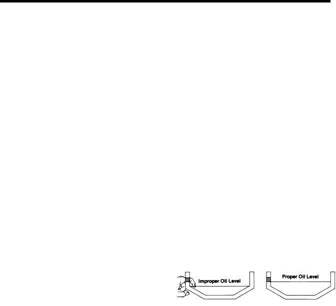
Make sure oil is level with filler opening. Be- |
||||||||||
I |
Every 500 hours |
|
Change transmission |
fluid |
where |
|
|
||||||||||||
|
|
|
severe dirt |
conditions |
exist. |
|
|
cause you |
can reach oil |
with your finger does |
|||||||||
I |
|
|
|
|
|
|
not mean oil is at proper level. One inch of oil |
||||||||||||
Every 1,000 hours |
|
|
Change transmission fluid |
|
|
||||||||||||||
|
|
|
|
(Normal off-highway use), |
|
|
level is about |
one |
gallon |
of oil. |
|
|
|||||||
|
|
|
|
|
|
|
|
|
|
|
|
|
|
|
|
||||
|
|
|
|
|
|
|
Draining |
Oil |
|
|
|
|
|||||||
|
|
|
Heavy Duty Engine Lubricant or |
|
|
|
|
|
|
|
|||||||||
|
|
|
Mineral Gear Lubricant |
|
|
|
|
|
Drain transmission while oil is warm. To drain |
||||||||||
|
|
|
|
|
|
|
|
|
|
|
|
||||||||
I |
|
|
|
HIGHWAY USE |
|
|
|
|
|
||||||||||
|
|
|
|
|
|
|
|
oil remove the drain plug at bottom of case. |
|||||||||||
I |
First 3,000 to 5,000 miles |
|
|
Factory fill |
|
|
Clean the drain plug before re-installing. |
||||||||||||
(4827 to 8045 Km) |
|
|
|
|
Initial |
drain. |
|
|
Refilling |
|
|
|
|
|
|
||||
Every 10,000 miles |
|
Inspect Iubricant |
level, |
|
|
|
|
|
|
|
|
||||||||
I |
|
|
|
Clean case around filler plug and remove plug |
|||||||||||||||
(16090 Km) |
|
|
|
Check for leaks, |
|
|
|||||||||||||
I |
|
|
|
|
|
|
from side of case. Fill transmission to the |
||||||||||||
Every 50,000 miles |
|
Change |
transmission |
|
|
||||||||||||||
(80450 Km) |
|
|
|
|
lubricant, |
|
|
level of the filler opening. If transmission has |
|||||||||||
I |
|
|
OFF-HIGHWAY USE |
|
|
|
|
|
two filler openings, fill to level of both open- |
||||||||||
|
|
|
|
|
|
|
|
|
|
|
|
ings. |
|
|
|
|
|
|
|
|
|
First 30 |
hours |
Change transmission lubricant on new |
units |
|
|
|
|
|
|
|
|
|
|||||
|
|
|
|
The exact amount of oil will depend on the |
|||||||||||||||
|
|
|
|
|
|
|
|
|
|
|
|
||||||||
|
|
|
|
|
|
|
|
|
|
|
|
||||||||
|
|
Every 40 |
hours |
|
Inspect Iubricant level Check for leaks |
|
|
transmission inclination and model. Do not |
|||||||||||
|
|
Every 500 hours |
|
Change transmission |
Iubricant |
where |
|
|
over fill—this |
will |
cause |
oil to be |
forced out |
||||||
|
|
|
|
|
severe dirt |
conditions |
exist. |
|
|
of the transmission. |
|
|
|
||||||
|
|
Every 1,000 hours |
|
Change transmission Iubricant |
|
|
When adding oil, types and brands of oil |
||||||||||||
|
|
|
|
|
|
(Normal off-highway use), |
|
|
should not be mixed because of possible in- |
||||||||||
|
Change the oil filter when fluid or lubricant is changed. |
4 |
compatibility. |
|
|
|
|
|
|||||||||||
,.. . . .
LUBRICATION
Operating Temperatures
—With Eaton® Roadranger ®
CD50 Transmission Fluid
Heavy Duty Engine Oil
and Mineral Oil
The transmission should not be operated consistently at temperatures above 250oF (120oC). However, intermittent operating temperatures to 300oF (149oC) will not harm the transmission. Operating temperatures above 250oF increase the lubricant’s rate of oxidation and shorten its effective life. When the average operating temperature is above 250oF, the transmission may require more frequent oil changes or external cooling.
The following conditions in any combination can cause operating temperatures of over 250oF: (1) operating consistently at slow speeds, (2) high ambient temperatures, (3) restricted air flow around transmission, (4) exhaust system too close to transmission, (5) high horsepower, overdrive operation.
External oil coolers are available to reduce operating temperatures when the above conditions are encountered.
Transmission Oil Coolers are:
Recommended
—With engines of 350 H.P. and above with overdrive transmissions
Required
—With engines 399 H.P. and above with overdrive transmissions and GCW’S over 90,000 lbs.
—With engines 399 H.P. and above and 1400 Lbs.-Ft. or greater torque
—With engines 450 H.P. and above
—With EP or Multipurpose Gear Oil
Mild EP gear oil and multipurpose gear oil are not recommended when lubricant operating temperatures are above 230°F (110). In addition, transmission oil coolers are not recommended with these gear oils since the oil cooler materials may be attacked by these gear oils. The lower temperature limit and oil cooler restriction with these gear oils generally limit their success to milder applications.
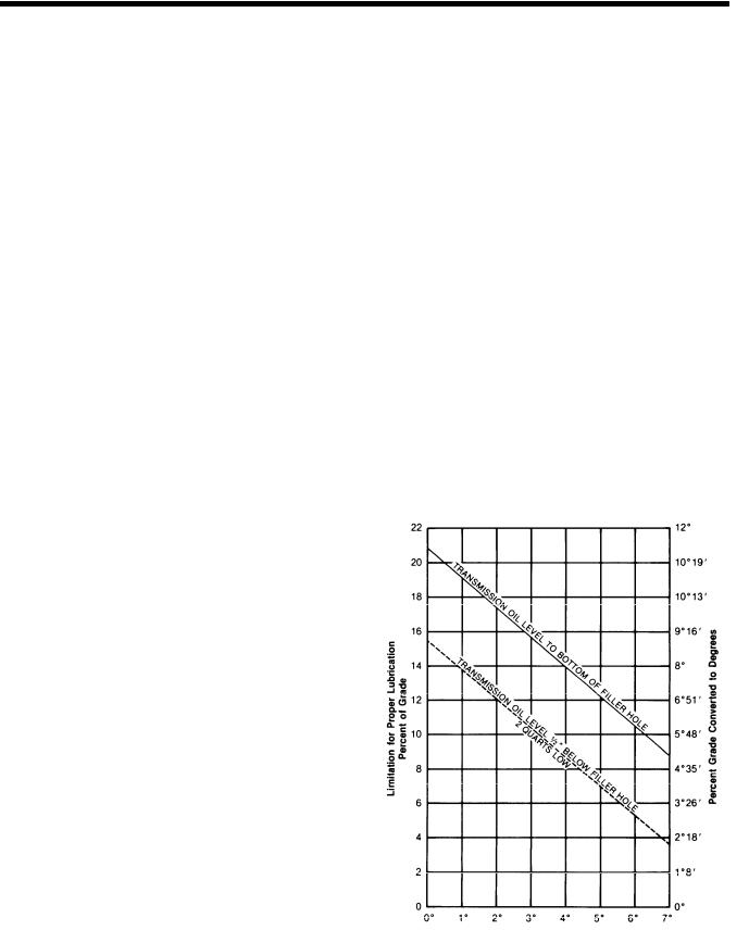
Proper Lubrication Levels as Related to Transmission Installation Angles
If the transmission operating angle is more than 12 degrees, improper lubrication can occur. The operating angle is the transmission mounting angle in the chassis plus the percent of upgrade (expressed in degrees).
The chart below illustrates the safe percent of upgrade on which the transmission can be used with various chassis mounting angles.
For example: if you have a 4 degree transmission mounting angle, then 8 degrees (or 14 percent of grade) is equal to the limit of 12 degrees. If you have a O degree mounting angle, the transmission can be operated on a 12 degree (21 percent) grade.
Anytime the transmission operating angle of 12 degrees is exceeded for an extended
period of time the transmission should be equipped with an oil pump or cooler kit to insure proper lubrication.
Note on the chart the effect low oil levels can have on safe operating angles. Allowing the oil level to fall 1/2” below the filler plug hole reduces the degree of grade by approximately 3 degrees (5.5 percent).
Proper Lubrication Levels are Essential!
Transmission Mounting Angle
Dotted line showing “2 Quarts Low” is for reference only. Not recommended.
OPERATION
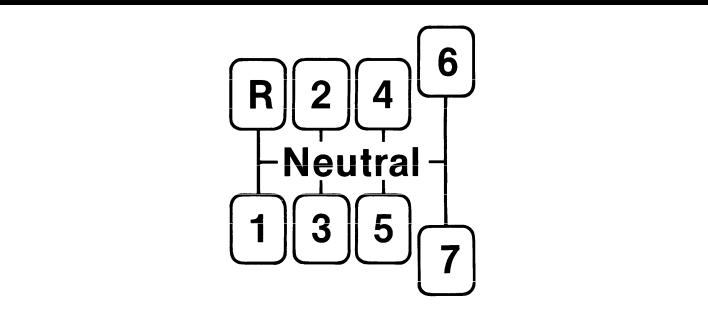
Shift Lever Patterns
The T-11607 transmissions have seven forward speeds and one reverse. All models are shifted as you would shift any non-synchronized manual transmission, following the simple 7-speed shift pattern. Always double-clutch when making lever shifts.
The longer lever throw in 6th and 7th gear positions provide greater clutching tooth contact.
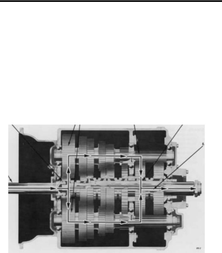
POWER FLOW
The transmission must transfer the engine's power in terms of torque to the vehicle's rear wheels. Knowledge of what takes place in the transmission during torque transfer is essential when trouble-shooting and making repairs become necessary.
1.Torque from the engine is transferred to the transmission's input shaft.
2.Splines of input shaft engage internal splines in hub of main drive gear.
3.Torque is split between the two countershaft drive gears.
4.Torque is delivered along both countershaft to countershaft gears of "engaged" mainshaft gear. The cross section view illustrates 1st speed gear engagement.
5.Internal clutching teeth in hub of engaged mainshaft gear transfers torque to mainshaft through sliding clutch.
6.Mainshaft transfers torque directly to output shaft.
2. |
3. |
4. |
5. |
|
1.
1st SPEED POWER FLOW
TIMING
All Fuller Twin countershaft transmissions are “timed” at assembly. It is important that proper timing procedures are followed when reassembling the transmission. Timing assures that the countershaft gears will contact the mating mainshaft gears at exactly the same time, allowing mainshaft gears to center on the mainshaft and equally divide the load.
Timing is a simple procedure of making the appropriate teeth of a gear set prior to installation and placing them in proper mesh while in the transmission.
A.Marking Countershaft Drive Gear Teeth
1.Prior to placing each countershaft assembly into case, mark the tooth located directly over the keyway of drive gear as shown. This tooth is stamped with an “O” to aid identification.
A.TOOTH MARKED ON EACH COUNTERSHAFT DRIVE GEAR FOR TIMING PURPOSES
B.Marking Main Drive Gear Teeth.
1.Mark any two adjacent teeth on the main drive gear.
2.Mark the two adjacent teeth located directly opposite the first set marked on the main drive gear. As shown below, there should be an equal number of unmarked gear teeth on each side between the marked sets.
B.TEETH MARKED ON MAIN DRIVE GEAR FOR TIMING PURPOSES
C.Meshing Marked Countershaft Drive Gear Teeth with Marked Main Drive Gear Teeth.
1.When installing the bearings on left counter-
shaft, mesh the marked tooth of countershaft drive gear with either set or two marked teeth on the main drive gear.
2.Repeat the procedure when installing the bearings on right countershaft (after installing mainshaft assembly), using the remain-
ing set of two marked teeth on the main drive gear to time assembly.
C. DRIVE GEAR SET PROPERLY

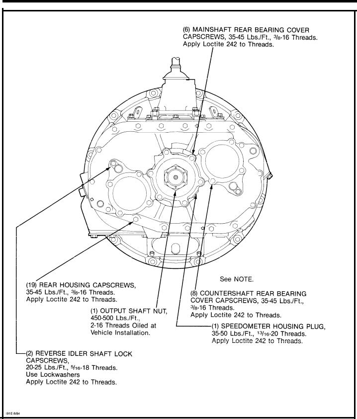
TORQUE RECOMMENDATIONS
Correct torque application is extremely important to assure long transmission life and dependable performance. Over-tightening or under-tightening can result in a loose installation and, in many instances, eventually cause damage to transmission gears, shafts, and/or bearings. Use a torque wrench whenever possible to attain recommended lbs./ft. ratings. Do not torque capscrews dry.
TORQUE RECOMMENDATIONS

TOOL REFERENCE
Some repair procedures pictured in this manual show the use of specialized tools. Their actual use is recommended as they make transmission repair easier, faster, and prevent costly damage to critical parts.
But for the most part, ordinary mechanic’s tools such as socket wrenches, screwdrivers, etc., and other standard shop items such as a press, mauls and soft bars are all that is needed to successfully disassemble and reassemble any Fuller Transmission.
The specialized tools listed below can be obtained from a tool supplier or made from dimensions as required by the individual user. Detailed Fuller Transmission Tool Prints are availabe upon request by writing.
Eaton Corporation Transmission Division Technical Service Dept. P.O. Box 4013
Kalamazoo, Michigan 49003
PAGE |
T O O L |
HOW OBTAINED |
|
|
|
|
|
2 5 |
Snap Ring Pliers |
Tool Supplier |
|
|
|
|
|
3 9 |
Mainshaft Hook |
Tool Supplier |
|
|
|
|
|
2 0 |
Tension Spring Driver |
Made from Fuller Transmission |
|
Print T-11938 |
|||
|
|
||
|
|
|
|
4 9 |
Snap Ring Pliers |
Tool Supplier |
|
|
|
|
|
3 8 |
Bearing Puller w/Set Screw |
Made from Fuller Transmission |
|
Print T-10325 |
|||
|
|
||
|
|
|
|
5 0 |
Bearing Drivers (Flanged-End) |
Made from Fuller Transmission |
|
Print Series T-10842* |
|||
|
|
||
|
|
|
|
5 0 |
Countershaft Support Tool |
Tool Supplier |
|
|
|
|
|
5 2 |
Input Shaft Nut Installer |
Made from Fuller Transmission |
|
Print T-22553-A |
|||
|
|
||
|
|
|
|
7 4 |
Torque Wrench, 1000 Lbs./Ft. Capacity |
Tool Supplier |
|
|
|
|
|
5 1 |
Input Shaft Bearing Driver |
Tool Supplier |
|
|
|
|
*Dimensions necessary to determine specific tool number required.
PREVENTIVE MAINTENANCE

PREVENTIVE MAINTENANCE
PREVENTIVE MAINTENANCE CHECK CHART
CHECKS WITHOUT PARTIAL
DISASSEMBLY OF CHASSIS OR CAB
1 . Clutch Housing Mounting
a.Check all capscrews in bolt circle of clutch housing for looseness.
2.Clutch Release Bearing (Not Shown)
a.Remove hand hole cover and check radial and axial clearance in release bearing.
b.Check relative position of thrust surface of release bearing with thrust sleeve on pushtype clutches.
3.Clutch Pedal Shaft and Bores
a.Pry upward on shafts to check wear.
b.If excessive movement is found, remove clutch release mechanism and check bushings in bores and wear on shafts.
4.Lubricant
a.Change at specified service intervals.
b.Use only the types and grades as recommended. See LUBRICATION.
5.Filler and Drain Plugs
a.Remove filler plugs and check level of lubricant at specified intervals. Tighten filler and drain plugs securely.
6.Capscrews and Gaskets
a.Check all capscrews, especially those on PTO covers and rear bearing covers for looseness which would cause oil leakage. See TORQUE RECOMMENDATIONS.
b.Check PTO opening and rear bearing covers for oil leakage due to faulty gasket.
8.Gear Shift Lever Housing Assembly
a.Remove the gear shift lever housing assembly from transmission.
b.Check tension spring and washer for set and wear.
c.Check the gear shift lever spade pin and spade in slot for wear.
d.Check bottom end of gear shift lever for wear and check slot of yokes and blocks in shift bar housing for wear at contact points with shift lever.
CHECKS WITH DRIVE LINE DROPPED
9.Universal Joint Companion Flange or Yoke Nut
a.Check for tightness. Tighten to recommended torque.
10.Output Shaft (Not Shown)
a.Pry upward against output shaft to check radial clearance in mainshaft rear bearing.
CHECKS WITH UNIVERSAL JOINT
COMPANION FLANGE OR YOKE
REMOVED
NOTE: If necessary, use solvent and shop rag to clean sealing surface of companion flange or yoke. DO NOT USE CROCUS CLOTH, EMERY PAPER OR OTHER ABRASIVE MATERIALS THAT WILL MAR SURFACE FINISH.
11.Splines on Output Shaft (Not Shown)
a. Check for wear from movement and chucking action of the universal joint companion flange or yoke.
7.Gear Shift Lever
a.Check for looseness and free play in housing. If lever is loose in housing, proceed with Check No. 9.
12.Mainshaft Rear Bearing Cover a. Check oil seal for wear.

PRECAUTIONS
Disassembly
It is assumed in the detailed disassembly instructions that the lubricant has been drained from transmission, the necessary linkage and air lines disconnected and the transmission has been removed from vehicle chassis. Removal of the gear shift lever housing assembly (or remote control assembly) is included in the detailed instructions (Disassembly and Reassembly—Shifting Controls); however, this assembly MUST be detached from shift bar housing before transmission can be removed.
FOLLOW CLOSELY EACH PROCEDURE IN THE DETAILED INSTRUCTIONS. MAKING USE OF THE TEXT. ILLUSTRATIONS AND PHOTOGRAPHS PROVIDED.
1BEARINGS — Carefully wash and relubricate all reusable bearings as removed and protectively wrap until ready for use. Remove bearings planned to be reused with pullers designed for this purpose.
2. ASSEMBLIES — When disassembling the various assemblies, such as the mainshaft, countershaft, and shift bar housing, lay all parts on a clean bench in the same sequence as removed. This procedure will simplify reassembly and reduce the possibility of losing parts.
3. SNAP RINGS — Remove snap rings with Pliers designed for this purpose. Snap rings removed in this manner can be reused, if they are not sprung or loose.
4 INPUT SHAFT — The input shaft can be removed from transmission without removing the coun-
Inspection
tershafts, mainshaft, or main drive gear. Special procedures are required and provided in this manual.
5. CLEANLINESS — Provide a clean place to work. It is important that no dirt or foreign material enters the unit during repairs, Dirt is an abrasive and can damage bearings. It is always good practice to clean the outside of the unit before starting the planned disassembly.
6. WHEN USING TOOLS TO MOVE PARTS — Always apply force to shafts, housings, etc, with restraint. Movement of some parts is restricted. Never apply force to the part being driven after it stops solidly. The use of soft hammers, bars and mauls for all disassembly work is recommended.
Before reassembling the transmission, check each part carefully for abnormal or excessive wear and damage to determine reuse or replacement. When replacement is necessary, use only genuine Fuller Transmission parts to assure continued performance and extended life from your unit.
Since the cost of a new part is generally a small fraction of |
the total cost of downtime and labor, avoid reus- |
|
ing a questionable part which could lead |
to additional repairs |
and expense soon after initial reassembly. To aid |
in determining the reuse or replacement of any transmission |
part, consideration should also be given to the |
|
unit’s history, mileage, application, etc. |
|
|
Recommended inspection procedures |
are provided in the |
following checklist. |
A.BEARINGS
1.Wash all bearings in clean solvent. Check balls, rollers and raceways for pitting, discoloration, and spalled areas. Replace bearings
that are pitted, discolored, or spalled.
2 . Lubricate bearings that are not pitted, discolored, or spalled and check for axial and radial clearances.
3 . Replace bearings with excessive clearances.
4 . Check bearing fits. Bearing inner races should be tight to shaft; outer races slightly tight to slightly loose in case bore. If bearing spins freely in bore, however, case should be replaced.
B.GEARS
1.Check gear teeth for frosting and pitting. Frosting of gear tooth faces present no threat of transmission failure. Often in continued
operation of the unit, frosted gears will “heal” and not progress to the pitting stage. And in most cases, gears with light to moderate pitted teeth have considerable gear life remaining and can be reused. But gears with advanced stage pitting should be replaced.
2. Check for gears with clutching teeth abnormally worn, tapered, or reduced in length from clashing in shifting. Replace gears found in any of these conditions.

PRECAUTIONS
Inspection (cont’d.)
3. Check axial clearance of gears. Where excessive clearance is found, check gear snap ring, washer, spacer, and gear hub for excessive wear. Maintain .005” to .012” axial clearance between mainshaft gears.
C. SPLINES
1. Check splines on all shafts for abnormal wear. If sliding clutch gears, companion flange, or clutch hub have worn into the sides of the splines, replace the specific shaft affected.
D.TOLERANCE/LIMIT WASHERS
1.Check surfaces of all limit washers. Washers scored or reduced in thickness should be replaced.
E.REVERSE IDLER GEAR ASSEMBLIES
1.Check for excessive wear from action of roller bearings.
F.GRAY IRON PARTS
1.Check all gray iron parts for cracks and breaks. Replace or repair parts found to be damaged. Heavy castings may be welded or brazed provided the cracks do not extend into bearing bores or bolting surfaces. When welding, however, never place the ground so as to allow current to pass through the transmission.
G.CLUTCH RELEASE PARTS
1.Check clutch release parts. Replace yokes worn at cam surfaces and bearing carrier worn at contact pads.
2.Check pedal shafts. Replace those worn at bearing surfaces.
H.SHIFT BAR HOUSING ASSEMBLY
1.Check for wear on shift yokes and blocks at pads and lever slot. Replace excessively worn parts.
2.Check yokes for correct alignment. Replace sprung yokes.
3.Check Iockscrews in yokes and blocks. Tighten and rewire those found loose.
4.If housing has been disassembled, check neutral notches of shift bars for wear from interlock balls.
I . GEAR SHIFT LEVER HOUSING ASSEMBLY
1.Check spring tension on shift lever. Replace tension spring and washer if lever moves too freely.
2.If housing is disassembled, check spade pin and corresponding slot in lever for wear. Re-
place both parts if excessively worn.
J. BEARING COVERS
1.Check covers for wear from thrust of adjacent bearing. Replace covers damaged from thrust of bearing outer race.
2.Check bores of covers for wear. Replace those worn oversize.
K.OIL RETURN THREADS AND SEALS
1.Check oil return threads in front bearing cover. If sealing action of threads has been destroyed by contact with input shaft, replace bearing cover.
2.Check oil seal in mainshaft rear bearing cover. If sealing action of lip has been destroyed, replace seal.
L.SLIDING CLUTCHES
1.Check all shift yokes and yoke slots in sliding clutches for extreme wear or discoloration from heat.
2.Check engaging teeth of sliding clutches for partial engagement pattern.

PRECAUTIONS
Reassembly
Make sure that interiors of case and housings are clean. It is important that dirt and other foreign materials be kept out of the transmission during reassembly. Dirt is an abrasive and can damage polished surfaces of bearings and washers. Use certain precautions, as listed below, during reassembly,
1.GASKETS - Use new gaskets throughout the transmission as it is being rebuilt. Make sure all gaskets are installed. An omission of any gasket can result in oil leakage or misalignment of bearing covers.
2.CAPSCREWS - To prevent oil leakage, use Loctite 242 thread sealant on all capscrews. For torque ratings, see TORQUE RECOMMENDATIONS.
3.O-RINGS - Lubricate all O-rings with silicon lubricant.
4.ASSEMBLY - Refer to the illustrations provided in
the |
detailed disassembly instructions as a guide |
to |
reassembly. |
5.INITIAL LUBRICATION - Coat all limit washers and splines of shafts with Lubriplate during reassembly to prevent scoring and galling of such parts.
6. AXIAL CLEARANCES - Maintain original axial clearances of .005” to .012” for mainshaft gears.
7.BEARINGS - Use of flanged-end bearing drivers is recommended for the installation of bearings. These special drivers apply equal force to both bearing races, preventing damage to balls/rollers and races while maintaining correct bearing alignment with bore and shaft. Avoid using a tubular or sleeve-type driver, whenever possible, as force is applied to only one of the bearing races. See TOOL REFERENCE.
8.UNIVERSAL JOINT COMPANION FLANGE OR YOKE - Pull the companion flange or yoke tightly into place with the output shaft nut, using 450-500 foot-pounds of torque. Make sure the speedometer drive gear or a replacement spacer of the same width has been installed. Failure to pull the companion flange or yoke tightly into place will permit the output shaft to move axially with resultant damage to the rear bearing.
IMPORTANT: REFER TO THE APPROPRIATE ILLUSTRATED PARTS LIST (SPECIFIED BY MODEL SERIES) TO ENSURE THAT PROPER PARTS ARE USED DURING REASSEMBLY OF THE TRANSMISSION.

CHANGING INPUT SHAFT
Special Procedure
In some cases, it may become necessary to remove only the input shaft due to clutch wear on the splines. In these cases the input shaft can be removed without disassembling the transmission other than removing the shift bar housing. Removal of the clutch housing is optional.
Disassembly
1.Remove the gear shift lever housing and shift bar housing.
2. Remove the front bearing cover capscrews.
3.Engage two of the mainshaft sliding clutches so that the mainshaft is locked up.
4.Use paint to mark one tooth on each side of the drive gear where it meshes with the countershaft gears. Mark the countershaft tooth on each side of the marked drive gear tooth. It is advisable to use different colored paint on each countershaft to avoid the possibility of re-installing the drive gear incorrectly.
5.Drive against the back face of the drive gear to move the assembly forward and from the case bore.
CAUTION:
DO NOT allow the mainshaft gearing to turn while the drive gear is removed.
6.Proceed with normal disassembly of the drive gear assembly.
Reassembly
1 . Insert the reassembled drive gear assembly into the case bore, returning the marked tooth on each side of the drive gear to its original position between the two marked teeth on each countershaft. It may be necessary to lift the front of the mainshaft slightly so that the mainshaft pilot enters the pocket in the input shaft. Drive against the front of the input shaft to fully seat the bearing in the case bore.
2.Re-install the front bearing cover, shift bar housing and gear shift lever housing.
DISASSEMBLY AND REASSEMBLY
SHIFTING CONTROLS
GEAR SHIFT LEVER HOUSING ASSEMBLY
A. Removal and Disassembly
1. Turn out retaining capscrews, jar lightly to break gasket seal and remove gear shift lever housing and gasket from shift bar housing.
NOTE: Remote control housings are removed from shift bar housing in the same manner. For disassembly and reassembly of LRC Assemblies, see Illustrated Parts List No. P-541. For disassembly and reassembly of SRC Assemblies, see Illustrated Parts List No. P-515.
2. Remove boot from gear shift lever and secure assembly in vise with bottom of housing up. Use a large screwdriver to twist between the spring and housing, forcing spring from under lugs in housing. Do one coil at a time.
DISASSEMBLY AND REASSEMBLY
SHIFTING CONTROLS
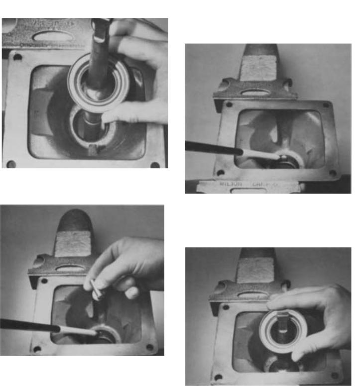
B. Reassembly of Gear Shift Lever
3.Remove tension spring, washer and gear shift lever from housing.
4. Remove spade pin from bore in housing tower. If necessary, remove the O-ring from groove inside tower.
1.With gear shift lever housing secured in vise as during disassembly, install spade pin in bore of housing tower. If previously removed, install O- ring in tower groove.
2.Position the gear shift lever in housing with spade pin in lever ball slot and install the tension spring washer over ball, dished-side up.
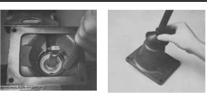
DISASSEMBLY AND REASSEMBLY SHIFTING CONTROLS
3. Install tension spring under lugs in housing, seating one coil at a time. Use of a spring driving tool is recommended.
4. Remove assembly from vise and install rubber boot over gear shift lever and against housing.

DISASSEMBLY AND REASSEMBLY SHIFTING CONTROLS
SHIFT BAR HOUSING ASSEMBLY
DISASSEMBLY AND REASSEMBLY
SHIFTING CONTROLS
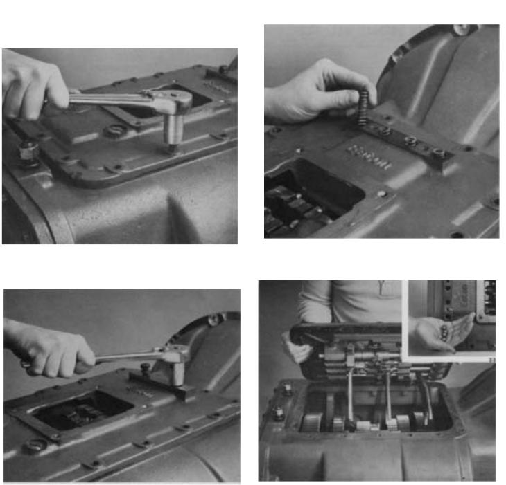
A. Removal and Disassembly
3. Remove four tension springs.
1. Turn out the retaining capscrews.
2.Turn out two capscrews and remove tension spring cover.
4. Jar housing lightly to break gasket seal and lift housing from transmission. Tip housing over to remove four balls in tension spring bores (inset).

DISASSEMBLY AND REASSEMBLY SHIFTING CONTROLS
5.Cut lockwire and remove machined capscrew from 1st and reverse shift block.
7. Cut lockwire, turn out Iockscrew and remove the 4-5th speed yoke, bar, and spacer. As the bar is pulled out of housing, remove interlock pin from the bar (inset).
6. Mount housing in a vise as indicated using caution to avoid marring machined surface. Cut lockwire, turn out Iockscrews and remove direct yoke, bar, and block from housing.
NOTE: When removing bars, remaining bars must be kept in neutral position or interlock parts will prevent removal.
8.Cut Iockwires, turn out Iockscrews and remove 2nd & 3rd speed yoke and block. Remove interlock pin from bar as it clears housing boss (inset).
 Loading...