


Service Manual
Fuller Heavy Duty Transmissions
TRSM0600
October 2007

For parts or service call us Pro Gear & Transmission, Inc.
1(877) 776-4600
(407)872-1901 parts@eprogear.com
906 W. Gore St. Orlando, FL 32805

TABLE OF CONTENTS
FOREWARD
MODEL DESIGNATIONS AND SPECIFICATIONS
LUBRICATION
OPERATION
POWER FLOW
TIMING
TORQUE RECOMMENDATIONS
TOOL REFERENCE
PREVENTIVE MAINTENANCE
PRECAUTIONS
DISASSEMBLY
INSPECTION
REASSEMBLY
AIR SYSTEM
OPERATION AND TROUBLESHOOTING
WITH 3-POSITION SELECTOR VALVE
WITH A-5015 ROADRANGER VALVE
AI R SYSTEM SCHEMATICS
DISASSEMBLY–SHIFTING CONTROLS
AI R SYSTEM
GEARSHIFT LEVER HOUSING
SHIFT BAR HOUSING ASSEMBLY
DISASSEMBLY - COMPANION FLANGE AND CLUTCH HOUSING DISASSEMBLY - AUXILIARY REAR HOUSING
DISASSEMBLY - AUXILIARY INTERMEDIATE HOUSING DISASSEMBLY - FRONT SECTION
REASSEMBLY - FRONT SECTION
REASSEMBLY - AUXILIARY INTERMEDIATE HOUSING REASSEMBLY - AUXILIARY REAR HOUSING
REASSEMBLY - COMPANION FLANGE AND CLUTCH HOUSING REASSEMBLY - SHIFTING CONTROLS
SHIFT BAR HOUSING
GEAR SHIFT LEVER HOUSING
AIR SYSTEM
1

FOREWORD
This manual is designed to provide detailed information necessary to service and repair the Fuller@ Transmission listed on the cover.
As outlined in the Table of Contents, the manual is divided into 3 main sections:
a.Technical information and reference
b.Removal, disassembly, reassembly and installation
c. Options
The format of the manual is designed to be followed in its entirety if complete disassembly and reassembly of the transmission is necessary. But if only one component of the transmission needs to be repaired, refer to the Table of Contents for the page numbers showing that component. For example, if you need to work on the Shift Bar Housing, you will find instructions for removal, disassembly and reassembly on page 19. Instructions for installation are on page 55. Service Manuals, Illustrated Parts Lists, Drivers Instructions, and other forms of product
service information for these and other Fuller Transmissions are available upon request. A Technical Literature Order Form may be found in the back of this manual. You may also obtain Service Bulletins, detailing information on product improvements, repair procedures and other service-related subjects by writing to the following address:
EATON CORPORATION TRANSMISSION DIVISION Technical Service Department P.O. Box 4013
Kalamazoo, MI 49003 (61 6) 342-3344
Every effort has been made to ensure the accuracy of all information in this brochure, However, Eaton Transmission Division makes no expressed or implied warranty or representation based on the enclosed information. Any errors or omissions may be reported to Training and Publications, Eaton Transmission Division, P.O. Box 4013, Kalamazoo, Ml 49003.
2

MODEL DESIGNATIONS
AND SPECIFICATIONS
Nomenclature:
|
|
|
|
RTO-6613 |
||||||||||
Letter Designations |
|
|
|
|
|
|
|
|
|
Number Designations |
|
|||
|
|
|
|
|
|
|||||||||
Roadranger |
|
|
|
|
|
|
|
|
|
|
|
Forward Speeds |
||
|
|
|
|
|
|
|
|
|
|
|
||||
Twin Countershaft |
|
|
|
|
|
|
|
|
|
Multi-Mesh Gearing |
||||
|
|
|
|
|
|
|
|
|||||||
Overdrive |
|
|
|
|
|
|
|
|
|
|
x 100 = Nominal Torque |
|||
|
|
|
|
|
|
|
|
|
|
|||||
|
|
|
|
|
|
|
|
|
|
|
|
|
Capacity |
|
IMPORTANT: All Fuller Transmissions are identified by model and serial number. This information is stamped on the transmission identification tag and affixed to the case.
DO NOT REMOVE OR DESTROY THE TRANSMISSION IDENTIFICATION TAG.
Specifications:
|
|
|
|
|
|
|
|
Gear Ratios |
|
|
|
|
|
|
(Note 1) |
(Note 2) |
(Note 2) |
(Note 3) |
|||
|
|
|
|
|
|
|
|
|
|
|
|
|
Relative Speed |
||||||||
|
|
|
Low |
|
|
Intermediate |
|
|
|
H i g h |
|
|
|
Length |
Weight |
Oil Cap. |
|||||
|
|
|
|
|
|
|
|
|
|
|
PTO Gear |
||||||||||
|
No. |
|
|
|
|
|
|
|
|
|
|
|
|
|
|
To Input R.P.M. |
In. |
Lbs. |
Pints |
||
|
|
|
|
|
|
|
|
|
|
|
|
|
|
|
|
|
mm |
k g |
Liters |
||
Model |
Speeds |
1 St |
2nd |
3rd |
4th |
5th |
6th |
7th |
8th |
9th |
10th |
11th |
12th |
13th |
Reverse |
Right |
Bottom |
||||
|
|
|
|||||||||||||||||||
|
|
|
|
|
|
|
|
|
|
|
|
|
|
|
|
|
|
|
|
|
|
RT-6613 |
13 |
17.93 |
14.04 |
10,96 |
8,61 |
6.74 |
5.26 |
4.11 |
3.29 |
2.61 |
2.05 |
1.60 |
1.25 |
1.00 |
2.78/9.15 |
720 |
.720 |
32.7 |
556 |
16 |
|
|
|
|
|
|
|
|
|
|
|
|
|
|
|
|
19.06 |
|
|
830 |
252 |
8 |
|
|
|
|
|
|
|
|
|
|
|
|
|
|
|
|
|
|
|
|
|
|
|
RTO-6613 |
13 |
14.38 |
11.26 |
8.78 |
6.90 |
5.41 |
4.22 |
3.29 |
2.64 |
2.10 |
1.64 |
1.28 |
1.00 |
.80 |
2.23/7.34 |
.898 |
.898 |
32.7 |
556 |
16 |
|
|
|
|
|
|
|
|
|
|
|
|
|
|
|
|
15,28 |
|
|
830 |
252 |
8 |
|
|
|
|
|
|
|
|
|
|
|
|
|
|
|
|
|
|
|
|
|
|
|
See Chart Notes.
CHART NOTES:
P.T.O. Gears - 6613 Series transmissions have a 33-tooth PTO gear, both right side and bottom. All models have 6/8 pitch PTO gears.
2. Length |
- Listed lengths are |
installation dimensions from face of clutch housing to front of bottoming sur- |
face of |
companion flange or |
yoke. |
3 . Weight - Listed weights are without clutch housing*. Weights include standard controls, which consist of gear shift lever housing, gear shift lever, range controls and attaching lines. Weight of standard controls is approximately 10 lbs. (4.5 kg). All weights are approximate.
4.Oil Capacity - Oil capacities are approximate, depending on inclination of transmission. Always fill transmission to level of filler opening. Refer to Publication Form 121- “Lubrication Recommendations” for further information.
*For information on available clutch housings refer to Publication FUL-140-’’Clutch Housing Chart”.
Proper Lubrication . . .
the Key to long transmission life
Proper lubrication procedures are the key to a good all-around maintenance program. If the oil is not doing its job, or if the oil level is ignored, all the maintenance procedures in the world are not going to keep the transmission running or assure long transmission life.
Fuller® Transmissions are designed so that the internal parts operate in a bath of oil circulated by the motion of gears and shafts.
Thus, all parts will be amply lubricated if these procedures are closely followed:
1.Maintain oil level. Inspect regularly.
2.Change oil regularly.
3.Use the correct grade and type of oil.
4.Buy from a reputable dealer.
Lubrication Change and Inspection
HIGHWAY USE
First 3,000 to |
|
Change |
transmission |
|||||
5,000 miles (4827 to 8045 Km) |
|
oil on new units |
||||||
|
|
|
|
|
||||
Every 10,000 miles (16090 Km) |
|
Inspect oil level. |
||||||
|
Check for leaks. |
|||||||
|
|
|
|
|||||
|
|
|
|
|||||
Every 50,000 miles |
|
Change |
transmission |
|||||
(80,450 |
Km) |
|
|
|
|
|
oil. |
|
|
|
|
|
|
||||
|
OFF-HIGHWAY USE |
|
|
|
||||
|
|
|
|
|
||||
First 30 |
hours |
|
Change |
transmission |
||||
|
|
|
|
oil on |
new |
units. |
||
|
|
|
|
|
||||
Every 40 hours |
Inspect oil |
level. Check |
for |
leaks. |
||||
|
|
|
|
|
|
|||
Every 500 hours |
Change |
transmission |
oil |
where |
||||
severe dirt |
conditions |
exist. |
||||||
|
|
|||||||
|
|
|
|
|||||
Every 1,000 hours |
Change |
transmission oil |
||||||
(Normal |
off-highway |
use). |
||||||
|
|
|||||||
Oil filter should be changed at each oil change on units equipped with optional external oil filter.
\
I
Recommended Lubricants
|
|
Fahrenheit |
|
|
(Celsius) |
|
Grade |
Ambient |
Type |
(SAE) |
Temperature |
|
|
|
Heavy Duty Engine Oil |
|
|
MIL-L-2104B, C or D or |
50 |
Above 10oF(-12oC.) |
API-SF or API-CD |
40 |
Above 10oF(-12oC.) |
(Previous API designations 30 |
Below 10oF(-12oC.) |
|
acceptable) |
|
|
|
|
|
Mineral Gear Oil with rust 90 |
Above 10oF(-12oC.) |
|
and oxidation inhibitor |
80W |
Below 10oF(-12oC.) |
API-GL-1 |
|
|
The use of mild EP gear oil or multi= purpose gear oil is not recommended, but ‘if these ‘gear oils are used, be sure to adhere to the following limitations:
Do not use mild EP gear oil or multi-pur- pose gear oil when operating temperatures are above 230oF (110oC). Many of these gear oils, particularly 85W140, break down above 230°F and coat seals, bearings and gears with deposits that may cause premature failures. If these deposits are observed (especially a coating on seal areas causing oil leakage), change to heavy duty engine oil or mineral gear oil to assure maximum component life and to maintain your warranty with Eaton. (Also see “Operating Temperatures”.)
Additives and friction modifiers are not recommended for use in Fuller transmissions.
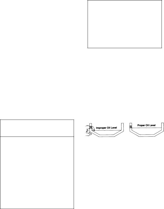
Proper Oil Level
Make sure oil is level with filler opening. Because you can reach oil with your finger does not mean oil is at proper level. One inch of oil level is about one gallon of oil.
Draining Oil
Drain transmission while oil is warm. To drain oil remove the drain plug at bottom of case. Clean the drain plug before re-installing.
Refilling
Clean case around filler plug and remove plug from side of case. Fill transmission to the level of the filler opening. If transmission has two filler openings, fill to level of both openings.
The exact amount of oil will depend on the transmission inclination and model. Do not over fill - this will cause oil to be forced out of the case through front bearing cover.
When adding oil, types and brands of oil should not be intermixed because of possible incompatibility.
4
Operating Temperatures —With Heavy Duty Engine Oil
and Mineral Oil
The transmission should not be operated consistently at temperatures above 250°F (120oC). However, intermittent operating temperatures to 300oF (149°C) will not harm the transmission. Operating temperatures above 250oF increase the lubricant’s rate of oxidation and shorten its effective life. When the average operating temperature is above 250oF, the transmission may require more frequent oil changes or external cooling.
The following conditions in any combination can cause operating temperatures of over 250oF: (1) operating consistently at slow speeds, (2) high ambient temperatures, (3) restricted air flow around transmission, (4) exhaust system too close to transmission, (5) high horsepower, overdrive operation.
External oil coolers are available to reduce operating temperatures when the above conditions are encountered.
Transmission Oil Coolers are:
Recommended
- With engines of 350 H.P and above with overdrive transmissions
Required
-With engines 399 H.P. and above with overdrive transmissions and GCW’S over 90,000 lbs.
-With engines 399 H.P. and above and 1400 Lbs.-Ft. or greater torque
-With engines 450 H.P. and above
-With EP or Multipurpose Gear Oil
Mild EP gear oil and multipurpose gear oil are not recommended when lubricant operating temperatures are above 230oF (110o). In addition, transmission oil coolers are not recommended with these gear oils since the oil cooler materials may be attacked by these gear oils. The lower temperature limit and oil cooler restriction with these gear oils genenally limit their success to milder applications.
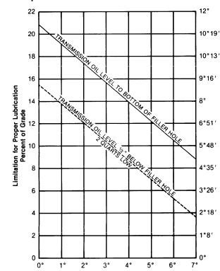
Proper Lubrication Levels
as Related to Operating Angles
If the transmission operating angle is more than 12 degrees, improper lubrication can occur. The operating angle is the transmission mounting angle in the chassis plus the percent of upgrade (expressed in degrees).
The chart below illustrates the safe percent of upgrade on which the transmission can be used with various chassis mounting angles.
For example: if you have a 4 degree transmission mounting angle, then 8 degrees (or 14 percent of grade) is equal to the limit of 12 degrees. If you have a O degree mounting angle, the transmission can be operated on a 12 degree (21 percent) grade.
Anytime the transmission operating angle of 12 degrees is exceeded for an extended period of time the transmission should be equipped with an oil pump or cooler kit to insure proper lubrication.
Note on the chart the effect low oil levels can have on safe operating angles. Allowing the oil level to fall 1/2” below the filler plug hole reduces the degree of grade by approximately 3 degrees (5.5 percent).
Proper Lubrication Levels are Essential!
Transmission Mounting Angle
Dotted line showing “2 Quarts Low” is for reference only. Not recommended.
5
OPERATION
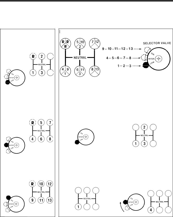
In the following instructions it is assumed that the driver is familiar with motor trucks and tractors, and that he can coordinate the necessary movements of the shift lever and clutch pedal to make progressive and selective gear engagements in either direction, up or down.
Use Normal Double Clutching Procedures Between Shifts.
Shift this Pattern with Selector Valve Button in LOW Range
Shift this Pattern with Selector Valve Button in INTERMEDIATE RANGE
RT-6613 Gear Shift Lever Pattern and Selector Valve Positions
NOTE: For RTO-6613 models, the 7/12 and 8/13 speed locations are reversed.
UPSHIFTING
1. With the transmission in neutral, start engine |
4. Shift from 1st speed through 2nd and to the |
and bring vehicle’s air pressure to normal. |
3rd speed gear position. |
2. Make sure the selector valve button is in the |
|
LOW range position, |
|
Shift this Pattern with Selector Valve |
3. Shift into the 1st speed gear position. See |
|
Button in DIRECT |
page relating to transmission countershaft |
|
brake, |
||
|
5. Move the selector valve button from LOW to iN-
TERMEDIATE range, |
and immediately shift to the |
||
4th speed |
gear position. After the selector valve |
||
is |
moved, |
the auxiliary |
will shift as soon as there |
is |
a relief |
in torque. |
|
6
OPERATION
6. Shift progressively from 4th through 5th, 6th, and 7th to the 8th speed gear position.
7. Move the selector valve button from iNTERMEDIATE to DIRECT range.
8. Move the gear shift lever to the 9th speed gear position. The auxiliary section will automatically shift from INTERMEDIATE to DIRECT when the gear shift lever reaches neutral.
9. Shift upward from 9th through 10th, 11th and 12th to the 13th speed gear position.
DOWNSHIFTING
1. Move the shift lever from the 13th speed position through each successive lower speed to the 9th speed gear position.
2. When in 9th and ready for the next down shift, move the selector valve button from DIRECT to INTERMEDIATE range.
3. Move the shift lever to the 8th speed gear position, As the lever reaches neutral the auxiliary will automatically shift from DIRECT to INTERMEDIATE range.
4. Shift from the 8th speed gear position through each gear and to 4th.
5. Move the selector valve button from iNTERMEDIATE to LOW and imrnediate/y shift to the 3rd speed gear position. The auxillary section will shift as soon as there IS a relief in torque.
6. Downshift from 3rd to 2nd and to 1st.
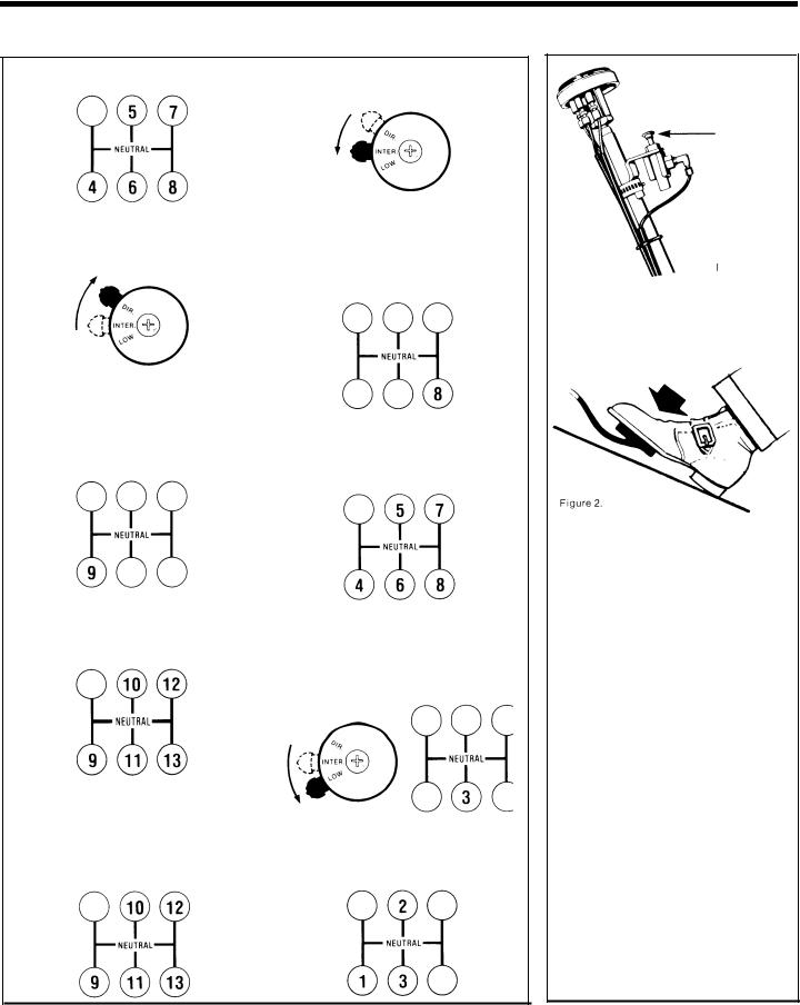
TCB-6 control button
Figure 1.
Model RTO-6613 transmission is equipped with either a Transmission Countershaft Brake, or an Upshift Clutch Brake.
Transmission Countershaft Brake . . .
Model TCB-6 or TCB-8 To be used only to assist /nitia/ gear engagement in first or reverse when vehicle is standing still.
Disengage clutch, press down control button and shift into first or reverse. (Figure 1.)
This is an air-operated mechanical brake which slows down the transmission gearing by forcing a piston against the transmission’s PTO gear.
Model TCB-6 mounts on the 6-bolt PTO opening, model TCB-8 mounts on the 8-bolt PTO opening.
Do not use an upshift brake. Use only when vehicle is standing still.
Clutch Brake . . . To provide a brake for initial gear engagement in first or reverse, and to provide a brake capable of use for upshifting when required with adverse conditions.
Brake is activated by extreme clutch pedal travel during regular upshift sequence. (Figure 2.)
The upshift clutch brake is a disc-type brake incorporated into the clutch and transmission drive gear cover assemblies.
When activated the upshift clutch brake slows down the transmission gearing.
Do not use when downshifting. Do not use as a brake to slow vehicle.
7
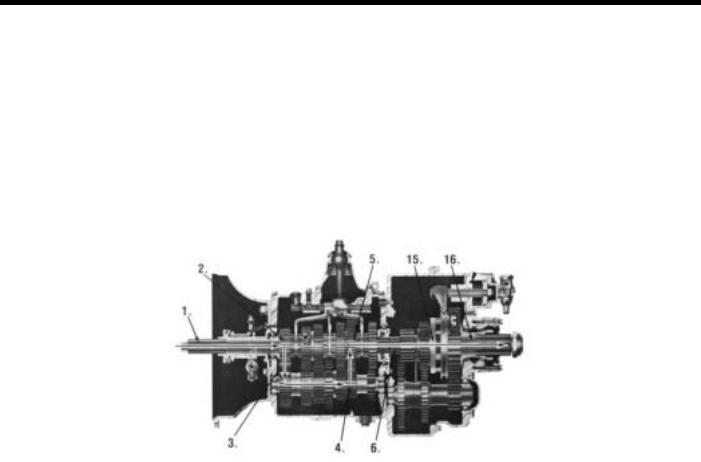
POWER FLOW
The transmission must efficiently transfer the engines power, in terms of torque, to the vehicles rear wheels. Knowledge of what takes place in the transmission during torque transfer is essential when troubleshooting and making repairs becomes necessary.
FRONT SECTION POWER FLOW:
1 . |
Power (torque) from the vehicles engine is transferred to the transmissions input shaft. |
|
||
2 . |
Splines of input shaft engage internal splines in hub of main drive gear. |
|
||
3 . |
Torque is split between the two countershaft drive gears and is delivered along countershaft to all |
counter- |
||
|
shaft gears. |
|
|
|
4 . |
Torque is transferred to "engaged" mainshaft gear. The following cross section views illustrate a 1st/4th/9th |
|||
|
speed gear engagement. |
|
|
|
5 . Internal clutching teeth in |
hub of |
engaged mainshaft gear transfers torque to mainshaft through |
sliding |
|
|
clutch. |
|
|
|
6 . |
Mainshaft transfers torque |
directly |
to auxiliary drive gear. |
|
8

POWER FLOW
Auxiliary Section Power Flow:
LO (with 3-Position Selector Valve)
Deep Reduction (with A-5015 Roadranger Valve)
7. |
The auxiliary drive gear |
splits torque between |
9. |
Torque |
is transferred to output shaft through |
|
the two auxiliary countershaft drive gears. |
|
sliding |
clutch. |
|
8. |
Torque is delivered along both countershaft to |
10. |
Torque |
is delivered to driveline (LO 1st shown). |
|
|
the "engaged" reduction |
gear on output shaft. |
|
|
|
LOW - POWER FLOW
Auxiliary Section Power Flow:
INTERMEDIATE (with 3-Position Selector Valve)
LO RANGE (with A-501 5 Roadranger Valve)
11. |
The intermediate drive gear splits torque be- |
1 3 . |
Torque |
is transferred to output shaft through |
|
tween the two auxiliary countershaft intermedi- |
|
sliding |
clutch. |
|
ate gears. |
14. |
Torque is delivered to driveline (INTERMEDIATE |
|
|
|
|||
12. |
Torque is delivered along both countershaft to |
|
RANGE |
4th shown). |
|
the "engaged" reduction gear on output shaft. |
|
|
|
INTERMEDIATE - POWER FLOW
9
POWER FLOW
Auxiliary Section Power Flow:
DIRECT (with 3-Position Selector Valve)
HI RANGE (with A-5015 Roadranger Valve)
15. The intermediate drive gear transfers torque 1 6 . |
Torque is delivered through output shaft to drive |
directly to the output shaft through "engaged" |
line (HIGH RANGE 9th shown). |
sliding clutch. |
|
10

TIMING
Timing Procedures: All ModeIs
All Fuller twin countershaft transmissions are “timed” at assembly. It is important that proper timing procedures are followed when reassembling the transmission. Timing assures that the countershaft gears will contact the mating mainshaft gears at the same time, allowing mainshaft gears to center on the mainshaft and equally divide the load.
Timing is a simple procedure of marking the appropriate teeth of a gear set prior to installation and placing them in proper mesh while in the transmission. In the front section, it is necessary to time only the drive gear set. And depending on the model, only the low range, deep reduction, or splitter gear set is timed in the auxiliary section.
Front Section
A.Marking countershaft drive gear teeth.
1.Prior to placing each countershaft assembly into case, clearly mark the tooth located directly over the keyway of drive gear as shown. This tooth is stamped with an “O” to aid identification.
A.TOOTH MARKED ON EACH COUNTERSHAFT DRIVE GEAR FOR TIMING PURPOSES
Cut 7300
B.Marking main drive gear teeth.
1.Mark any two adjacent teeth on the main drive gear.
2.Mark the two adjacent teeth located directly opposite the first set marked on the main drive gear. As shown below, there should be an equal number of unmarked gear teeth on each side between the marked sets.
B.TEETH MARKED ON MAIN DRIVE GEAR FOR TIMING PURPOSES
Cut 7300A
C. Meshing marked countershaft drive gear teeth with marked main drive gear teeth.
(After placing the mainshaft assembly into case, the countershaft bearings are installed to complete installation of the countershaft assemblies.)
1.When installing the bearings on left countershaft, mesh the marked tooth of countershaft drive gear with either set or two marked teeth on the main drive gear.
2.Repeat the procedure when installing the bearings on right countershaft, making use of
the remaining set of two marked teeth on the main drive gear to time assembly.
C u t 7 3 0 0 B |
C. DRIVE GEAR SET PROPERLY |
|
TIMED |
Auxiliary Section
Refer to page 89 for detailed instructions on timing the auxiliary section.
11

TORQUE RECOMMENDATIONS
—
YOKE LOCKSCREWS,
35·45 Ft.·Lbs., 7/16·20 Threads, Secure with Lock Wire.
~
_
SHIFT BAR HOUSING CAPSCREWS, 35·45 Ft.·Lbs., 3/8-16 Threads
RANGE SHIFT YOKE CAPSCREWS, 50-65 Ft.·Lbs., 112-20 Threads, Secure with Lock Wire.
\ |
AUXILIARY DRIVE GEAR RETAINER |
|
|
~k~~-~L~:.~~g~-~f~hreads. |
|
\ |
|
AUXILIARY RANGE SHIFT |
\ |
~;.~~N~~~b;.~~,~~i~~~~;;ws, |
|
~ \ |
\ |
Apply Loctite 242 to threads. |
Apply Loctite 242 to threads. |
|
\ . |
RANGE CYLINDER SHIFT BAR |
|
||||
1 |
|
~\ |
\~NUT, |
|
|
|||
|
|
|
|
|
|
70-85 Ft.·Lbs., 5/8·18 Threads with |
|
|
|
|
|
|
|
|
Nylon Locking Patch. |
|
|
1 |
|
REVERSE SIGNAL SWITCH PLUG, |
\ |
|
|
~AIR FILTER/REGULATOR |
|
|
|
|
|
|
|
||||
|
|
35·50 Ft.·Lbs., 9/16·18 Threads. |
|
|
|
CAPSCREWS, |
|
|
|
|
|
|
|
8-12 Ft.·Lbs., 1/4-20 Threads. |
|
||
STUDS |
\ |
|
|
|
Apply Loctite 242 to threads. |
|
||
60 Ft.·Lbs. Minimum, Driven Until |
|
|
|
\ |
REAR BEARING COVER |
|||
Bottomed, 5/8·11 Thread, |
~ |
|
|
|
CAPSCREWS |
|
||
Installed with Fuller No. 71204 Sealant. |
\ |
|
|
35.45 Ft.·Lbs.: 3/8·16 Threads. |
||||
L......1 |
|
CLUTCH HOUSING NUTS, \ |
~ |
|
~""~Apply Loctite 242 to threads. I |
|||
1 |
|
|
|
|
|
|
|
|
1 |
|
|
|
|
|
|
|
|
~ |
~t::.o-2oo~I\ |
|
~ |
f |
||||
|
|
|
|
|
|
|
|
1 |
CLUTCH HOUSING CAPSCREWS,
1/2-13 Threads, 80-100 Ft.-Lbs.,
Use Lockwashers.
FRONT BEARING COVER |
|
CAPSCREWS, |
REVERSE IDLER SHAFT NUTS. |
35.45 Ft.-Lbs., 3/8-16 Threads. |
50-60 Ft.-Lbs., 5/8-18 Threads with |
Apply Loctite 242 to threads. |
Nylon Locking Insert. |
(
INTERMEDIATE SHIFT YOKE LOCKSCREW,
35·45 Ft.·Lbs., 7/16·20 Threads, Secure with Lock Wire.
AUXILIARY RANGE SHIFT CYLINDER CAPSCREWS,
35·45 Ft.·Lbs., 3/8·16 Threads, Apply Loctite 242 to threads.
7190 B-6/86
12

TORQUE RECOMMENDATIONS
SUPPORT STUD NUTS,
170-185 Ft.-Lbs., 5/8 Threads, Use
Lockwashers.
I
AUXILIARY COUNTERSHAFT /\~ BEARING COVER CAPSCREWS,
35-45 Ft.·Lbs., 3/8-16 Threads Apply Loctite 242 to threads.
INTERMEDIATE CYLINDER PLUG,
40-50 Ft.-Lbs., 5/8-18 Threads.
SLAVE VALVE CAPSCREWS,
8-12 Ft.·Lbs., 1/4-20 Threads. Apply Loctite 242 to threads.
\
SPEEDMETER HOUSING PLUG, 35.75 Ft.-Lbs., 13/16-20 Threads, Use Fuller No. 71205 Sealant
\
LARGE P.T.0. COVER CAPSCREWS, 50·65 Ft.-Lbs., 7/16-14 Threads
Use Lockwashers. Apply Loctite 242 to threads.
Cut 7191 B-6/86
13

TOOL REFERENCE
Tool Reference
Some illustrations in this manual show the use of specialized tools. These tools are recommended for transmission repair as they make repair easier, faster and prevent costly damage to critical parts.
Some of these tools can be obtained from a regular tool supplier, while others can be made either from prints or dimensions as required by the individual user.
Listed below are illustrations which show these specialized tools, the tool name and how it can be obtained.
Prints are available for tools which have a Fuller |
tool number; |
send requests |
to the Service Department. |
||||
|
|
Eaton |
Corporation |
|
|
|
|
|
|
Transmission Division |
|
|
|||
|
|
P.O. Box 4013 |
|
|
|
|
|
|
|
Kalamazoo, Michigan |
49003 |
|
|
|
|
|
|
|
|
|
|
||
|
PAGE |
TOOL |
|
|
HOW OBTAINED |
||
|
|
|
|
|
|
|
|
|
4 3 |
Tension Spring Driver |
|
|
Made |
from Fuller |
|
|
|
|
Print T-1 1938 |
||||
|
|
|
|
|
|
|
|
|
52, 66, 77 |
|
|
|
|
|
|
|
86, 88, 98 |
Snap Ring Pliers, Large |
|
Tool |
Supplier |
||
|
|
|
|
|
|
|
|
|
69, 71 |
Snap Ring |
Pliers, Medium |
|
|
|
|
|
83, 84 |
(Needle-Nose Type) |
|
|
Tool |
Supplier |
|
|
|
|
|
|
|
|
|
|
|
|
|
|
|
Made |
from Fuller |
|
53 |
Aux. Countershaft Bearing |
Puller |
|
Print T-10325 |
||
|
|
|
|
|
|
|
|
|
62 |
Bearing Puller, Small |
|
|
|
|
|
|
(Jaw Type) |
|
|
Tool |
Supplier |
||
|
|
|
|
|
|
|
|
|
53, 98 |
Auxiliary Plate Hanger Bracket |
|
Made |
from Fuller |
||
|
|
Print T-22823 |
|||||
|
|
|
|
|
|
|
|
|
78, 84, 85, 86 |
|
|
|
|
Made |
from Fuller |
|
87, 94, 98 |
Bearing Drivers |
(Flange-end type) |
|
Print Series T-18042* |
||
|
|
|
|
|
|
|
|
|
|
|
|
|
|
Made |
from Fuller |
|
9 4 |
Oil Seal Driver |
|
|
Print T-18088-36 |
||
|
|
|
|
|
|
||
|
101 |
Torque Wrench, 1000 Ft.-Lb. Capacity |
|
Tool |
Supplier |
||
|
|
|
|
|
|
|
|
*Dimensions necessary to determine specific tool number required.
14

PREVENTIVE MAINTENANCE
15

PREVENTIVE MAINTENANCE
Preventive Maintenance Check Chart
CHECKS WITHOUT PARTIAL DISASSEMBLY OF CHASSIS OR CAB
1.Clutch Housing Mounting
a.Check all capscrews in bolt circle of clutch housing for looseness.
2.Clutch Release Bearing (Not Shown)
a.Remove hand hole cover and check radial
and axial clearance in release bearing.
b.Check relative position of thrust surface of release bearing with thrust sleeve on pushtype clutches.
3.Clutch Pedal Shaft and Bores
a.Pry upward on shafts to check wear.
b.If excessive movement is found, remove clutch release mechanism and check bushings in bores and wear on shafts.
4.Lubricant
a. Change at specified service intervals.
b.Use only the types and grades as recommended. See LUBRICATION.
5.Filler and Drain Plugs
a.Remove filler plug or dip stick and check level of lubricant at specified intervals. Tighten filler and drain plugs securely.
6.Capscrews and Gaskets
a.Check all capscrews, especially those on PTO covers and rear bearing covers for
looseness which would cause oil leakage. See TORQUE RECOMMENDATIONS.
b.Check PTO opening and rear bearing covers for oil leakage due to faulty gasket.
8.Gear Shift Lever Housing Assembly
a.Remove the gear shift lever housing assembly from transmission.
b.Check tension spring and washer for set and wear.
c.Check bottom end of gear shift lever for wear of slots. Also check for wear of finger assembly.
CHECKS WITH DRIVE LINE DROPPED
9 . Universal Joint Companion Flange
or Yoke Nut
a.Check for tightness. Tighten to recommended torque.
10.Output Shaft (Not Shown)
a.Pry upward against output shaft to check radial clearance in mainshaft rear bearing.
CHECKS WITH UNIVERSAL JOINT COMPANION FLANGE OR YOKE REMOVED
NOTE: If necessary, use solvent and shop rag to clean sealing surface of companion flange or yoke before reinstalling. DO NOT USE CROCUS CLOTH, EMERY PAPER OR OTHER ABRASIVE MATERIALS THAT WILL MAR SURFACE FINISH.
11.Splines on Output Shaft (Not Shown)
a.Check for wear from movement and chucking action of the universal joint companion flange or yoke.
7.Gear Shift Lever
a.Check for looseness and free play in housing. If lever is loose in housing, proceed with Check No. 8.
12.Mainshaft Rear Bearing Cover a. Check oil seal for wear.
16

PRECAUTIONS
Disassembly
It is assumed in the detailed disassembly instructions that the lubricant has been drained from the transmission, the necessary linkage and air lines removed and the transmission has been removed from the chassis. Removal of the gear shift lever housing assembly is included in the detailed instructions; however, this assembly must also be removed from transmission before removing unit from vehicle.
Follow each procedure closely in each section, making use of both the text and pictures.
1.BEARINGS - Carefully wash and relubricate all bearings as removed and protectively wrap until ready for use. Remove bearings with pullers designed for this purpose.
2.ASSEMBLIES - When disassembling the various assemblies, such as the mainshaft, countershaft and shifting bar housing, lay all parts on a clean bench in the same sequence as removed. This procedure will simplify reassembly and reduce the possibility of losing parts.
3.SNAP RINGS - Remove snap rings with pliers designed for this purpose. Snap rings removed in this manner can be reused, if they are not sprung or loose.
4.INPUT SHAFT - The input shaft can be removed without removing the countershaft, mainshaft or drive gear. Special procedures are required and are provided in this manual.
5.CLEANLINESS - Provide a clean place to work. It is important that no dirt or foreign material enters the unit during repairs. The outside of the unit should be carefully cleaned before starting the disassembly. Dirt is an abrasive and can damage bearings.
6.WHEN DRIVING - Apply force to shafts, housings, etc., with restraint. Movement of some parts is restricted. Do not apply force after the part being driven stops solidly. Use soft hammers and bars for all disassembly work.
Inspection
Before reassembling the transmission, the individual parts should be carefully checked to eliminate those damaged from previous service. This inspection procedure should be carefully followed to insure the maximum life from the transmission.
The cost of a new part is generally a small fraction of the total cost of downtime and labor, should the use of a questionable part make additional repairs necessary before the next regularly scheduled overhaul.
Recommended |
inspection procedures are set forth |
in the following |
check list: |
A. Bearings
1.Wash all bearings in clean solvent. Check balls, rollers and races for pits and spalled areas. Re-
place bearings which are pitted or spalled.
2.Lubricate bearings which are not spalled or pitted and check for axial and radial clearances. Replace bearings with excessive clearances.
3.Check fit of bearings in case bores. Bearings should be tight to shaft, slightly tight to slightly loose to bearing bore.
B. Gears
1.Check operating gear teeth for pitting on the tooth faces. Gears with pitted teeth should be replaced.
2.Check all engaging clutching teeth. Gears with clutching teeth worn, tapered or reduced in length from clashing in shifting should be replaced.
3.Check axial clearances of gears. Where excessive clearance is found, check gear snap ring, washer, spacer and gear hub for excessive wear. Maintain
.005 to .012 axial clearance of mainshaft forward speed gears, .005 minimum on reverse gear.
c. Splines
1.Check splines on all shafts for wear. If sliding clutch gears, companion flange or clutch hub have worn into the sides of the splines, replace the specific shaft affected.
D. Tolerance Washers
1.Check surfaces of all tolerance washers. Washers scored or reduced in thickness should be replaced.
E. Reverse Gear and Shaft
1.Check bearing sleeve for wear from action of roller bearings.
F.Gray Iron Parts
1.Check all gray iron parts for cracks and breaks. Replace or repair parts found to be damaged. Heavy castings may be welded or brazed providing the cracks do not extend into bearing bores or bolting surfaces.
G.Clutch Release Parts
1.Check clutch release parts. Replace yokes worn at cam surfaces and bearing carrier worn at contact pads.
2.Check pedal shafts. Replace those worn at bearing surfaces.
17
PRECAUTIONS
H. Shifting Bar Housing Assembly
1.Check yokes and blocks for wear at pads and lever slot. Replace worn parts.
2.Check yokes for alignment. Replace those which are sprung.
3.Check yokes for excessive wear; replace worn yokes.
4.Check Iockscrews in yokes and blocks. Retorque and rewire those found loose.
5.If housing has been dismantled, check neutral
notches of shifting bars for wear from interlock balls. Bars indented at points adjacent to the neutral notch should be replaced.
I.Gear Shift Lever Housing Assembly
1.Check spring tension on shift lever. Replace tension spring and washer if lever moves too freely.
2.If housing is dismantled, check pivot or spade pin and corresponding slot in lever for wear. Replace both parts if worn.
J.Oil Return Threads and Seals
1.Check oil return threads in front bearing cover. If sealing action of threads has been destroyed by
contact with input shaft, replace the cover.
2.Check oil seal in mainshaft rear bearing cover. If sealing action of lip has been destroyed, replace seal.
K.Synchronizers
1.Check high and low range synchronizers for burrs, uneven and excessive wear at contact surface, and metal particles.
2. Check blocker pins for excessive wear or looseness.
3.Check synchronizer contact surfaces on the high and low range gears for excessive wear.
L. Sliding Clutches
1. Check all yokes and yoke slots in sliding clutches for wear or discoloration from heat.
2.Check engaging teeth of sliding clutches for partial engagement pattern.
M. O-Rings
1.Check all O-rings for cuts, cracks or distortion. Replace if worn.
Reassembly
Make sure that interiors of case and housings are clean. It is important that dirt be kept out of transmission during reassembly. Dirt is abrasive and can damage polished surfaces of bearings and washers. Use certain precautions as listed below, during reassembly.
1.GASKETS - Use new gaskets throughout the transmission as it is being rebuilt. Make sure all gaskets are installed, as omission of gasket can result in oil leakage or misalignment of bearing covers.
2.CAPSCREWS - To prevent oil leakage, use thread sealant on all capscrews. See torque rating chart for recommended torque.
3.O-RINGS - Lubricate all O-rings with silicone lubricant.
4.ASSEMBLY - Refer to the disassembly illustrations as a guide to reassembly.
5.INITIAL LUBRICATION - Coat all tolerance washers and splines of shafts with Lubriplate during installation to provide initial lubrication, preventing scoring and galling.
6.AXIAL CLEARANCES - Maintain original axial clearances of mainshaft forward speed gears of
.005” to .012”. Mainshaft reverse gear clearance is a minimum of .005”.
7.BEARINGS - Use of flanged-end bearing drivers is recommended for the installation of bearings. These drivers apply equal force to both races of bearing, preventing damage to balls and races and maintaining correct bearing alignment with shaft and bore. If tubular or sleeve type driver is used, apply force only to inner race.
8.UNIVERSAL JOINT COMPANION FLANGE— Pull the companion flange tightly into place with the mainshaft nut, using 450-500 foot-pounds of torque. Make sure the speedometer gear has been installed on yoke. If a speedometer gear is not used, a replacement spacer of the same width must be used. Failure to pull the yoke or flange tightly into place will permit the shaft to move axially with resultant damage to rear bearing.
18
AIR SYSTEM
19

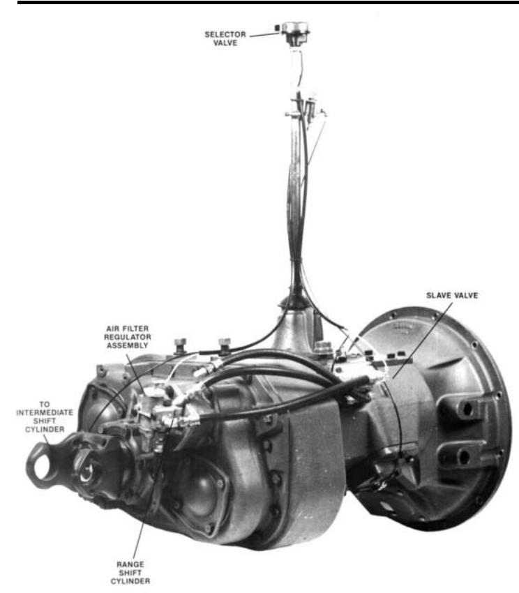
AIR SYSTEM
Cut 7061 M-1/86 |
WITH 3-POSITION SELECTOR VALVE |
— . .
This air system is found on 613/6613 Series Roadranger transmissions. The system consists of a 3- position selector valve and an Intermediate Shift Cylinder in addition to the Range Cylinder. The lntermediate Shift Cylinder shifts the transmission between LOW & INTERMEDIATE, the Range Cylinder shifts the transmission between INTERMEDIATE and
HIGH RANGE.
The *A-5015 Roadranger valve can also be used on this air system and is discussed later in this section.
*Requires the use of part no. 21676 INTERMEDIATE Shift Cylinder Cover.
20
AIR SYSTEM
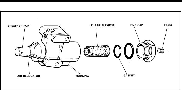
Air Filter/ReguIator Assembly
Cut 6141-1/86
Air Filter/Regulator
The air filter/regulator contains a replaceable filter element which can be removed by turning out the end cap. This element should be cleaned or replaced at each oil change, or more often under high humidity conditions.
With normal vehicle air pressure and the gear shift
lever |
in neutral, |
check |
the breather port on the side |
of the |
regulator. |
There |
should be no air leaking from |
the port. If there is a steady leak of air from this port, this indicates a defective regulator which should be replaced.
Cut off the vehicle air pressure and install an air gauge in the output port of the regulator. Bring the vehicle air pressure back to normal. Regulated air pressure should be 57 1/2 to 62 1/2 ppsi.
21
AIR SYSTEM
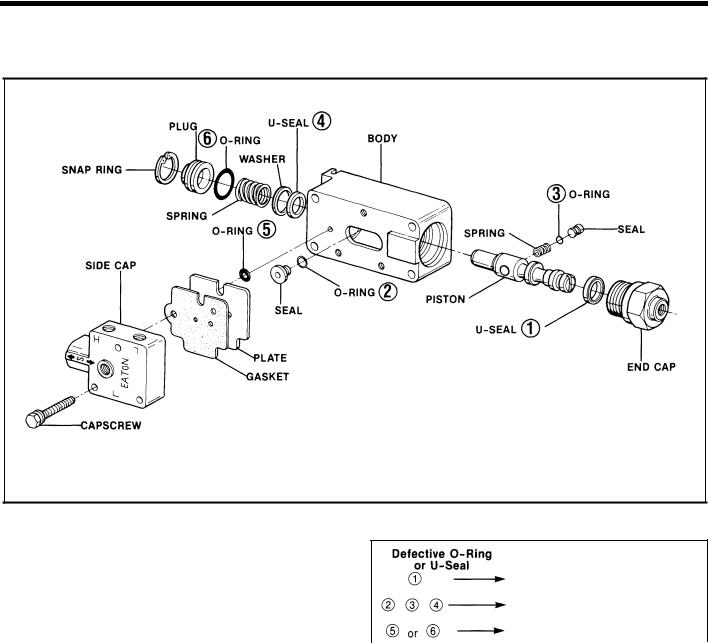
A-5000 SLAVE VALVE
Cut 6162 A-1 /86
Troubleshooting
The four O-rings and two U-seals are indicated by circled numbers on the above drawing. If any of these are defective there will be a constant air leak out the exhaust or to the atmosphere. In normal
operation |
exhaust will occur only for an instant as |
the range |
shift is made. The chart to the right is to |
be used as a guide to determine defective O-rings or U-seals.
To Disassemble the A-5000 Slave Valve
1.Disconnect all air lines, turn out the four capscrews and remove the slave valve from the transmission.
2.Turn out the three capscrews and remove the side cap.
3.Remove the seal from the piston and remove the O-ring from the seal.
4.Remove the spring from the piston.
5.Turn out the end cap from the valve body and remove the piston from the bore.
6.Remove the U-seal from the piston.
|
RESULT |
|
Constant leak through exhaust in |
|
low range only. |
|
Constant leak through exhaust in |
|
both ranges. |
1 |
Constant leak to atmosphere. |
|
7 . Remove the nylon plug from the piston and remove the O-ring from the plug.
8.Remove the snap-ring from the bore in front of the valve body.
9.Remove plug, spring, washer and U-seal from valve body bore. Remove O-ring from plug.
10.Lubricate all O-rings and U-seals with silicone lubricant and reassemble the slave valve.
11. When reinstalling the end cap, do not use more than 40 lbs. /ft. of torque. Overtorquing may result in binding the piston in the valve bore.
22
AIR SYSTEM
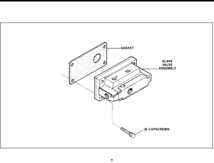
19470 Poppet - Type Slave Valve
Cut 7090 G-1/86
O p e r a t i o n Troubleshooting
The poppet-type slave valve is a non-serviceable valve. Should this valve prove to be defective the complete assembly must be replaced. There are, however, some preliminary checks to make before replacing the valve.
Check air fittings and air lines between the slave valve and range-valve for restrictions. A restriction in the line between the outlet port of the range valve and the “P” port of slave valve can cause a constant air leak out the exhaust port of the slave valve.
●Check the torque of the four 1/4” slave valve mounting capscrews. Torque to 8 lbs./ft. and determine if
the valve functions properly. If the capscrews are not torqued correctly an air leak between the slave valve and the transmission case could result.
 If retorquing the four slave valve capscrews eliminates the air leaks, the valve should be removed from the transmission and the three #10 Phillips head base plate screws on the back of the valve should be torqued to 45 lbs./in. If the four slave valve retaining capscrews are equipped with star washers, flat washers should be installed under the star washers to prevent them from fretting into the valve. Reinstall the valve and torque capscrews to 8 lbs./ft.
 If the valve continues to leak after the above checks have been made, the valve should be replaced.
23
AIR SYSTEM
With 3-Position Selector Valve
INTERMEDIATE SHIFT CYLINDER ASSEMBLY
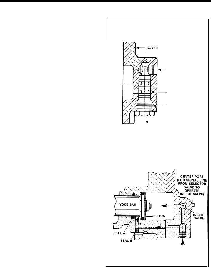
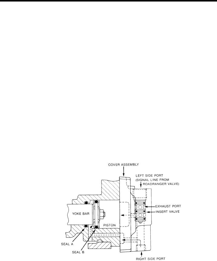
Operation
Constant, regulated air is channeled through the cover to the front side of shift piston — air is always on this side of piston.
The shift piston is moved by removing or applying air (from constant supply) to the backside of piston. This piston area is larger and can overcome the area of front side of piston. The removal or application of air on backside of piston is controlled by the insert valve in cylinder cover; this valve in turn is controlled by the selector valve.
Troubleshooting Cover Assembly
1.Exhaust Port — Any constant flow of air out the cover exhaust port usually indicates a faulty insert valve. Exhaust should occur briefly ONLY
when the selector valve button is moved from “low” to “intermediate”.
2.Insert Valve — A faulty insert valve, leaking at the
outer diameter O-rings or inner seals will result in failure to shift. Two indications of O-ring or seal failures are:
A.Constant leak out cover exhaust.
B.Constant leak out selector valve exhaust port “E” with the selector valve button in “low”, (providing the selector valve is operating properly).
The three O-rings on outer diameter of the insert valve can be replaced. If an inner seal is damaged, the entire insert valve will have to be re- p l a c e d .
Troubleshooting Cylinder
There are two O-ring seals in the intermediate shift cylinder.
1. Leak at Seal A - Possible |
failure |
to |
shift or slow |
shift to intermediate or |
direct |
plus |
pressurizing |
of transmission. |
|
|
|
2. Leak at Seal B - Slow shift between low and intermediate plus leak out cover exhaust when in intermediate or direct.
INTERMEDIATE SHIFT
CYLINDER COVER ASSEMBLY
CENTER PORT,
SIGNAL LINE FROM
SELECTOR VALVE
INSERT VALVE
RETAINING NUT
BOTTOM EXHAUST PORT
Cut 7450-4/84
INTERMEDIATE SHIFT
CYLINDER ASSEMBLY
COVER ASSEMBLY
SIDE PORT
(CONSTANT AIR)
Cut 7444 G-1 /86
24
AIR SYSTEM
With 3-Position Selector Valve
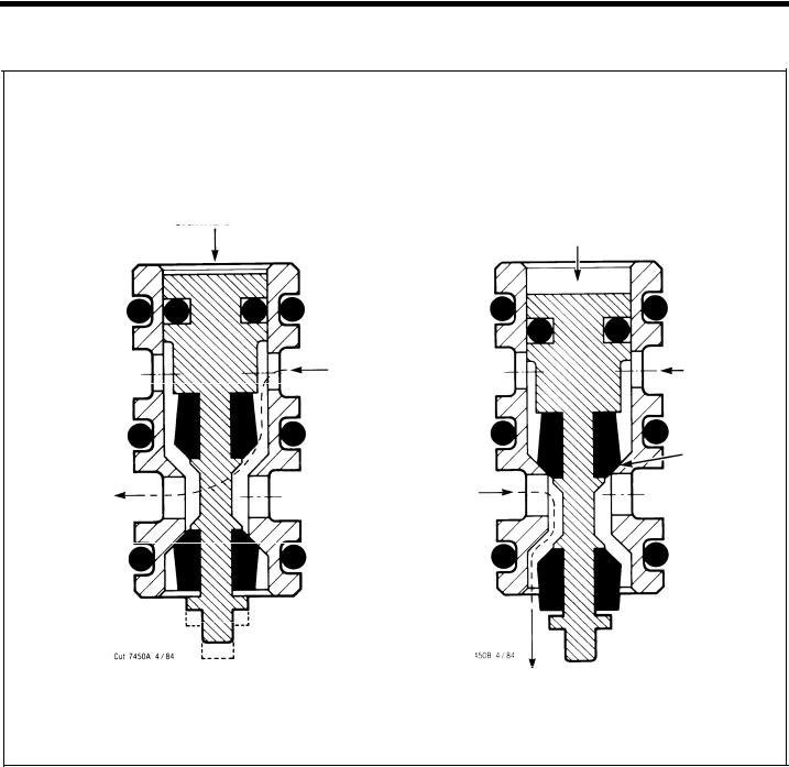
INSERT VALVE
LOW RANGE |
INTERMEDIATE AND DIRECT RANGE |
NO AIR ON
SIGNAL LINE AIR APPLIED THROUGH SIGNAL LINE
PUSHES INSERT VALVE PISTON DOWN
CONSTANT |
– CONSTANT |
AIR |
AIR |
CONSTANT AIR
SEALED OFF AT
AT THIS POINT
TO BACK SIDE
OF PISTON,
PUSHING SHIFT
BAR FORWARD
AIR EXHAUST THROUGH BOTTOM
PORT FROM BACK SIDE OF PISTON
The insert valve located in the intermediate shift cylinder cover is a small 13/16” valve. It is installed with the flat surface to the inside. It is secured with a special nut in bottom bore of cover.
When installing insert valve apply Fuller silicone lubricant (Pt. No. 71206) or its equivalent to cylinder walls. When installing special nut apply Fuller adhesive sealant (Pt. No. 71205) to threads.
The insert valve is self-contained and cannot be disassembled except for the three O-rings on outer diameter. These three O-rings are a stationary seal and do not move in cylinder.
Travel of the small piston in insert valve is only
1/32”. The insert valve is a normally-open valve. Thus, when there is no signal or delivery of air to top side of insert piston, the constant air from regulator passes through the insert valve and to the backside of the piston and moves the shift bar forward (low).
When the insert valve piston is activated by a signal or delivery of air, the insert valve is closed and shuts off the constant air to the backside of shift piston. Air in shift cylinder is exhausted out the insert valve and bottom bore of cover.
When air is removed from backside of shift piston, constant air on frontside of shift piston moves the shift bar to the rear (intermediate and direct).
25
AIR SYSTEM
With 3-Position Selector Valve
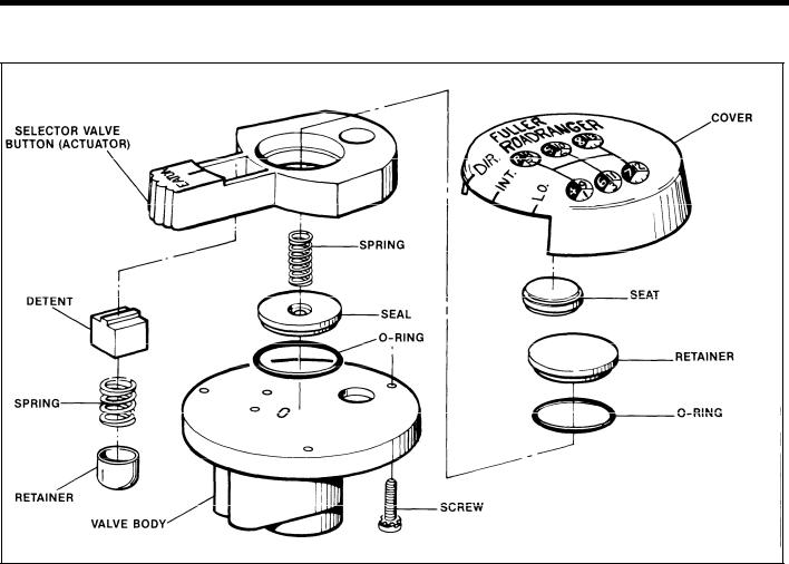
 SELECTOR VALVE
Cut 6151 A-1/84
Description
Porting - There are four ports in the bottom of the |
2 . |
Maintenance and Assembly |
- The selector |
valve |
||||||||||||||
selector valve: |
|
|
|
|
|
|
is disassembled by removing the cover screws. |
|||||||||||
A. The port stamped “S” is the |
supply |
port and |
|
Critical |
assembly factors |
|
are: |
|
|
|||||||||
is the constant air line from |
the slave valve. |
|
A. Make sure that the jam nut locking the selec- |
|||||||||||||||
B. The port stamped “E” is the exhaust port and |
|
tor |
valve to |
the |
shifting lever |
is secure. |
|
|||||||||||
is left open. |
|
|
|
|
|
|
B. Make sure that when reassembled, the top |
|||||||||||
C. The port stamped “R” is the |
signal line to |
the |
|
plate screws are torqued securely. A loose top |
||||||||||||||
|
plate |
can |
affect |
valve |
operation. |
|
||||||||||||
slave valve. |
|
|
|
|
|
|
|
|||||||||||
|
|
|
|
|
|
C. When |
reassembling, |
lubricate |
the O-ring and |
|||||||||
D. The port stamped “F” is the signal line to the |
|
|||||||||||||||||
intermediate |
shift cylinder. |
|
|
|
|
O-ring carrier with a |
silicone |
lubricant. |
|
|||||||||
|
|
|
|
|
|
|
If the above results are not obtained, disconnect |
|||||||||||
Troubleshooting |
|
|
|
|
|
the supply air line at the “S” port and make sure |
||||||||||||
1. With the selector valve button |
in “LO” |
position, |
|
that a |
steady |
flow |
of |
air |
is |
coming through the |
||||||||
|
line. If |
air is |
present, |
this |
would |
indicate a |
faulty |
|||||||||||
disconnect the |
two lines |
connected to |
port |
“R” |
|
|||||||||||||
|
selector valve. Cause |
can |
be |
defective |
parts, |
|||||||||||||
and “F”. There |
should be |
no air coming out |
of |
|
||||||||||||||
|
damaged |
O-ring |
or |
loose |
top |
plate screw. |
|
|||||||||||
these ports. |
|
|
|
|
|
|
|
|||||||||||
|
|
|
|
|
|
Any steady flow |
of |
air from the selector valve ex- |
||||||||||
Move the selector valve button to “lNT”. There |
3 . |
|||||||||||||||||
should now be a steady flow of air coming from |
|
haust post indicates a faulty selector valve or in- |
||||||||||||||||
the “F” port, but still no air coming from the “R” |
|
correct hook-up. Cause can be damaged O-ring, |
||||||||||||||||
port. |
|
|
|
|
|
|
defective parts, loose top plate screws or re- |
|||||||||||
Move the selector valve button to the “DIR” posi- |
|
versed |
air |
lines |
on |
the selector. |
|
|
||||||||||
|
|
|
|
|
|
|
|
|
|
|
|
|
||||||
tion. There should now be a steady flow of air |
|
|
|
|
|
|
|
|
|
|
|
|
|
|||||
coming from both the “F” |
and |
“R” ports. |
|
|
|
|
|
|
|
|
|
|
|
|
|
|
||
26
AIR SYSTEM
With A-5015 Roadranger Valve
INTERMEDIATE SHIFT CYLINDER ASSEMBLY
Note: When an A-5015 Roadranger valve is used the #21676 Intermediate Shift Cylinder cover must also be installed. Refer to the air system schematics at the end of this section for proper air line connections when retrofitting or troubleshooting. The air line connections are different for each system.
Operation
Constant, regulated air is channeled through the cover to the front side of shift piston — air is always on this side of piston.
The shift piston is moved by removing or applying air (from constant supply) to the backside of piston.
This piston area |
is larger and can overcome the area |
||||
of |
front |
side of |
piston. The removal or |
application of |
|
air |
on |
backside |
of piston is controlled |
by |
the insert |
valve in |
cylinder |
cover; this valve in turn is |
controlled |
||
B.Constant leak out Roadranger valve exhaust port “E” with the Roadranger valve button in “Deep Reduction”, (providing the Roadranger valve is operating properly).
The three O-rings on outer diameter of the insert valve can be replaced. If an inner seal is damaged, the entire insert valve will have to be replaced.
by the Roadranger Valve.
Troubleshooting Cover Assembly
1.Exhaust Port - Any constant flow of air out the cover usually indicates a faulty insert valve. Exhaust should occur briefly ONLY when the selec-
tor |
valve button is moved from “Deep Reduction” |
to |
“LO Range”. |
2.Insert Valve — A faulty insert valve, leaking at the outer diameter O-rings or inner seals will result in failure to shift. Two indications of O-ring or seal failures are:
A. Constant leak out cover exhaust.
Troubleshooting Cylinder
There are two O-rings seals in the intermediate shift cylinder.
1. Leak at Seal A - Possible failure to shift or slow shift to LO Range or HI Range plus pressurizing of transmission.
2. Leak at Seal B - Slow shift between Deep Reduction and LO Range plus leak out cover exhaust when in LO Range or HI Range.
CUI 7450 D-8/86
INTERMEDIATE SHIFT CYLINDER ASSEMBLY
27
 Loading...