


Service Manual
Fuller Medium Heavy Transmissions
TRSM0200
October 2007

For parts or service call us Pro Gear & Transmission, Inc.
1(877) 776-4600
(407)872-1901 parts@eprogear.com
906 W. Gore St. Orlando, FL 32805
TABLE OF CONTENTS
Model Designations Description Specifications Lubrication
Preventive Maintenance Torque Recommendations Timing
Precautions Shifting Controls
Removal and Disassembly Changing input Shaft Reassembly and installation Tool Reference
MODEL DESIGNATIONS
“T” = Twin Countershaft
“O” = Used as a letter, denotes Overdrive model
“11” x 100 = 1100 Ibs.-ft. torque capacity rating
“6” = Denotes “multi-mesh” gearing
“05” = Five forward speeds
“A”, “B”, etc. = Following numbers indicates a specific set of ratios
Since the models in the T-11605 series are identical in construction, references in this manual apply to all models unless stated otherwise. This includes models not listed above which may have other ratio combinations, designated by letters following the numerals.
ADDITIONAL LITERATURE
The following additional literature is available for the transmissions covered in this manual. Write: Marketing Communications, Eaton Corporation, Transmission Division, North American Headquarters, P.O. Box 4013, Kalamazoo, Michigan 49003. Phone: (616) 342-3344.
P-533 Illustrated Parts List |
16848 |
Shift Label T-1 1605 |
|
102 |
Trouble Shooting Guide |
16849 |
Shift Label TO-1 1605 |
121 |
Lubrication Recommendations |
|
|
THE T-11605 SERIES TRANSMISSIONS
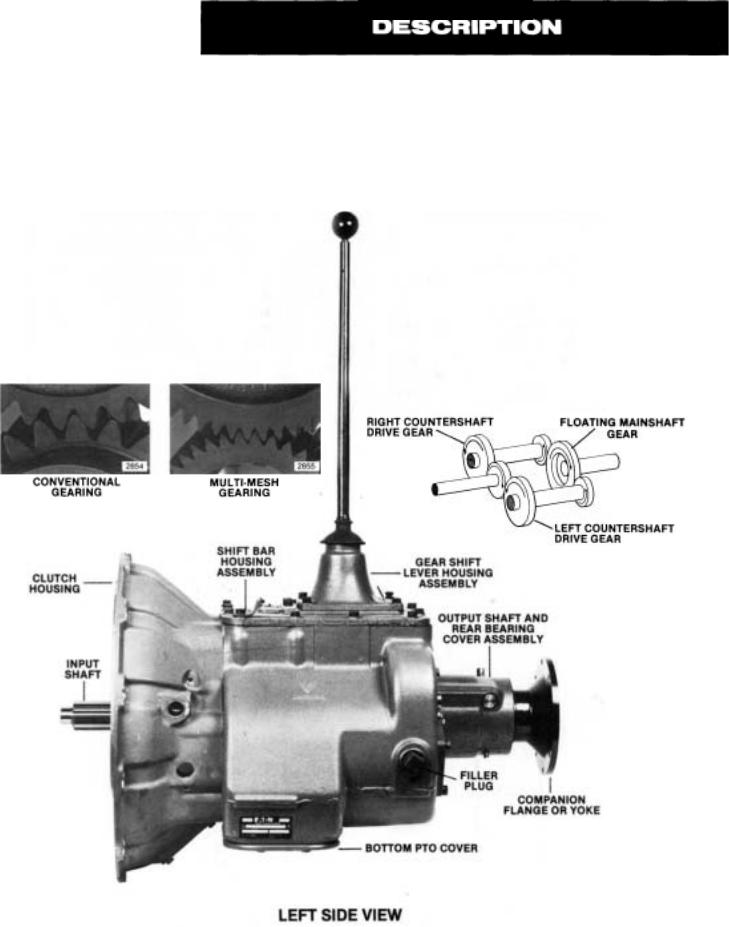
The New Generation T-11605 series transmissions, like the proven T-905 series they supersede, are designed with five forward speeds and one reverse for medium to heavy duty on-highway vehicles. The significant difference, however, is that most of the coarse pitch conventional gearing of the T-905 series has been replaced by the fine pitch "multimesh" gearing of the New Generation Series.
Multi-mesh gearing means there are two or three teeth per gear always in contact during torque transfer, instead of just one or two as with conventional gearing. With reduced stress on individual gear teeth, this multiple contact insures better distribution of engine torque through a smoother, less-nosier power flow that ultimately extends gear and bearing life.
The twin countershaft design, which splits torque equally between the two shafts to provide a high torque capacity to weight ratio, remains unchanged. Because of torque splitting, each gear set carries only half the load, greatly reducing the face width of each gear. Only the countershaft gears which mate with multi-mesh mainshaft gears have been changed to the new gearing concept.
Another unique design feature, also unchanged from the T-905 series, is the floating gear principle. The mainshaft gears, when not engaged, "float" between the countershaft gears, eliminating the need for gear sleeves and bushings. Only the 1stspeed and reverse gears are of the conventional gearing type. The remaining forward speed gears of the mainshaft have been changed to the new multi-mesh gearing concept.
2865
2857
GEAR RATIOS
MODELS
Speed |
|
T-11605A |
TO-11605A |
T-11605B |
TO-11605B |
T-11605C |
TO-11605C |
T-11605D |
|
TO-11605Dl |
T-11605M |
T-11605F |
||||||
5th |
1.00 |
.66 |
|
1.00 |
.86 |
1.00 |
.85 |
|
1.00 |
|
|
|
|
|
|
|
||
4th |
|
|
|
|
1.16 |
1.00 |
1.18 |
1.00 |
|
1.31 |
|
|
|
|
|
|
|
|
3rd |
|
|
|
|
2.04 |
1.75 |
2.12 |
1.80 |
|
2.05 |
|
|
|
|
|
|
|
|
2nd |
3.75 |
2.46 |
|
3.75 |
3.23 |
3.90 |
3.32 |
|
3.23 |
|
2.46 |
|
2.66 |
|
3.90 |
|||
|
|
|
|
|
||||||||||||||
1 St |
6.35 |
4.16 |
|
6.35 |
5.46 |
7.20 |
6.12 |
|
5.46 |
|
4.16 |
|
5.46 |
|
7.20 |
|||
Reverse |
6.48 |
4.25 |
|
6.48 |
5.57 |
7.09 |
6.03 |
|
5.57 |
|
4.25 |
|
5.57 |
|
7.09 |
|||
GEAR CHART
|
|
|
|
|
C.S. |
|
|
|
C.S. |
|
|
|
C.S. |
|
|
C.S. |
|
|
C.S. |
|
C.S. |
|
MODEL |
|
|
DRIVE |
DRIVE |
|
M.S. |
|
|
M.S. |
|
M.S. |
M.S. |
WITH |
|
WITH |
|||||||
|
|
|
GEAR |
GEAR |
|
4TH |
|
4TH |
|
3RD |
3RD |
|
2ND |
2ND |
1ST |
|
1ST |
|
REV. |
|||
T-11605A |
|
|
40-T |
75-T |
|
52-T |
|
64-T |
|
56-T |
44-T |
|
66-T |
33-T |
44-T |
|
13-T |
|
11-T |
|||
19646 |
|
19647 |
19171 |
19175 |
19612 |
|
19613 |
19177 |
19178 |
|
19082 |
14720 |
|
14720 |
||||||||
|
|
|
|
|
||||||||||||||||||
TO-11605A |
|
|
52-T |
64-T |
|
40-T |
|
75-T |
|
56-T |
44-T |
|
66-T |
33-T |
44-T |
|
13-T |
|
11-T |
|||
19168 |
|
19167 |
19648 |
19649 |
19612 |
|
19613 |
19177 |
19178 |
|
19082 |
14720 |
|
14720 |
||||||||
|
|
|
|
|
||||||||||||||||||
TO-11605B |
|
|
40-T |
75-T |
|
44-T |
|
71-T |
|
50-T |
46-T |
|
66-T |
33-T |
44-T |
|
13-T |
|
11-T |
|||
19646 |
|
19647 |
19182 |
19181 |
19620 |
|
19621 |
19177 |
19178 |
|
19082 |
14720 |
|
14720 |
||||||||
|
|
|
|
|
||||||||||||||||||
TO-11605B |
|
|
44-T |
71-T |
|
40-T |
|
75-T |
|
50-T |
46-T |
|
66-T |
33-T |
44-T |
|
13-T |
|
11-T |
|||
19166 |
|
19164 |
19648 |
19649 |
19620 |
|
19621 |
19177 |
19178 |
|
19082 |
14720 |
|
14720 |
||||||||
|
|
|
|
|
||||||||||||||||||
T-11605C |
|
|
40-T |
78-T |
|
44-T |
|
73-T |
|
50-T |
46-T |
|
66-T |
33-T |
48-T |
|
13-T |
|
11-T |
|||
19191 |
|
19190 |
19634 |
19635 |
19620 |
|
19621 |
19177 |
19178 |
|
15470 |
15475 |
|
15475 |
||||||||
|
|
|
|
|
||||||||||||||||||
TO-11605C |
|
|
44-T |
73-T |
|
40-T |
|
78-T |
|
50-T |
46-T |
|
66-T |
33-T |
48-T |
|
13-T |
|
11-T |
|||
19636 |
|
19637 |
19194 |
19186 |
19620 |
|
19621 |
19177 |
19178 |
|
15470 |
15475 |
|
15475 |
||||||||
|
|
|
|
|
||||||||||||||||||
T-11605D |
|
|
44-T |
71-T |
|
52-T |
|
64-T |
|
56-T |
44-T |
|
66-T |
33-T |
44-T |
|
13-T |
|
11-T |
|||
19166 |
|
19164 |
19171 |
19175 |
19612 |
|
19613 |
19177 |
19178 |
|
19082 |
14720 |
|
14720 |
||||||||
|
|
|
|
|
||||||||||||||||||
TO-11605D |
|
|
52-T |
64-T |
|
44-T |
|
71-T |
|
56-T |
44-T |
|
66-T |
33-T |
44-T |
|
13-T |
|
11-T |
|||
19168 |
|
19167 |
19182 |
19181 |
19612 |
|
19613 |
19177 |
19178 |
|
19082 |
14720 |
|
14720 |
||||||||
|
|
|
|
|
||||||||||||||||||
T-11605M |
|
|
44-T |
71-T |
|
52-T |
|
64-T |
|
50-T |
46-T |
|
56-T |
34-T |
44-T |
|
13-T |
|
11-T |
|||
19166 |
|
19164 |
19171 |
19175 |
19620 |
|
19621 |
19624 |
19625 |
|
19082 |
14720 |
|
14720 |
||||||||
|
|
|
|
|
||||||||||||||||||
T-11605F |
|
|
40-T |
78-T |
|
50-T |
|
67-T |
|
50-T |
46-T |
|
66-T |
33-T |
48-T |
|
13-T |
|
11-T |
|||
19191 |
|
19190 |
19984 |
19985 |
19620 |
|
19621 |
19177 |
19178 |
|
15470 |
15475 |
|
15475 |
||||||||
|
|
|
|
|
||||||||||||||||||
M.S. = MAINSHAFT
C.S. = COUNTERSHAFT
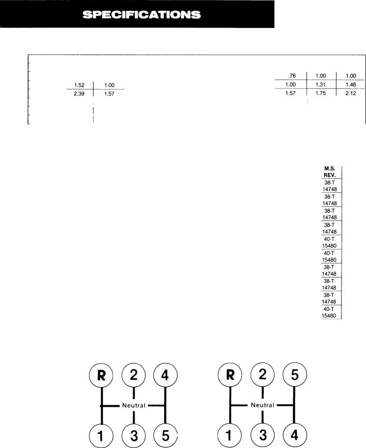
GEAR SHIFT PATTERN
2858 |
2859 |
Shifting Diagram for |
Shifting Diagram for |
T-1 1605 Model Transmissions |
TO-1 1605 Model Transmissions |

Clutch Release Mechanism—
Push - type clutches - single and 2-Plate – Clutch release bearing carrier, release bearing, extended front bearing cover, release yoke, pedal shafts and pedal adjusting arm furnished.
Pull-Type 2-Plate Clutches — Flat bearing cover machined for clutch brake furnished. Secure release yoke, pedal shafts, and pedal adjusting arm from clutch manufacturer.
Power Take-Off–
Openings—SAE Standard.
Right Side—Regular duty type, 6-bolt, short length.
Bottom—Heavy duty type, 8-bolt.
PTO Gears—
Right Side—45-tooth, 6/8 pitch gear.
Bottom—47-tooth, 6/8 pitch gear.
PTO Drive Gear Speeds—
Both openings, turning at engine speed:
T-11605A, T-11605 B . . . . . . . . . . ...533 TO-11605A, TO-11605D . . . . . . . ...813 TO-11605B, T-11605D,
T-11605 M . . . . . . . . . . . . . . . . ...619 T-11605C, T-11605 F . . . . . . . . . . . ..513 TO-11605C . . . . . . . . . . . . . . . . . . ..603
Constant mesh type PTO required on all overdrive models, both openings; on T-11605C models, both openings; and on T-11605B right side. (PTO gears are conventional mesh, not multimesh.)
Torque Capacity—
Diesel engines up to 370 hp, 1150 Ibs.-ft. torque (1559 N.m).
Torque rating is to be used as a guide and not as an approval. For an approval, submit complete vehicle specifications as outlined on Specification Form No. 62-14.
Speedometer Drive—
Provision is made in the rear bearing cover for the installation of speedometer gears and attachment of cable.
Reverse Light Switch—
Provision is made in the shift bar housing for the installation of a reverse light switch.
Weight—
With Standard Controls, SAE No. 1 aluminum clutch housing, less clutch release parts— 429 lbs. (195 Kg).
Oil Capacity–
Approximately 22 pints (10 Liters), depending upon inclination of engine and transmission.
Note: Fill to level of case filler opening.
Magnetic Oil Cleaners—
Two magnetic discs are installed in bottom of case to catch and hold metallic particles deposited in the oil.
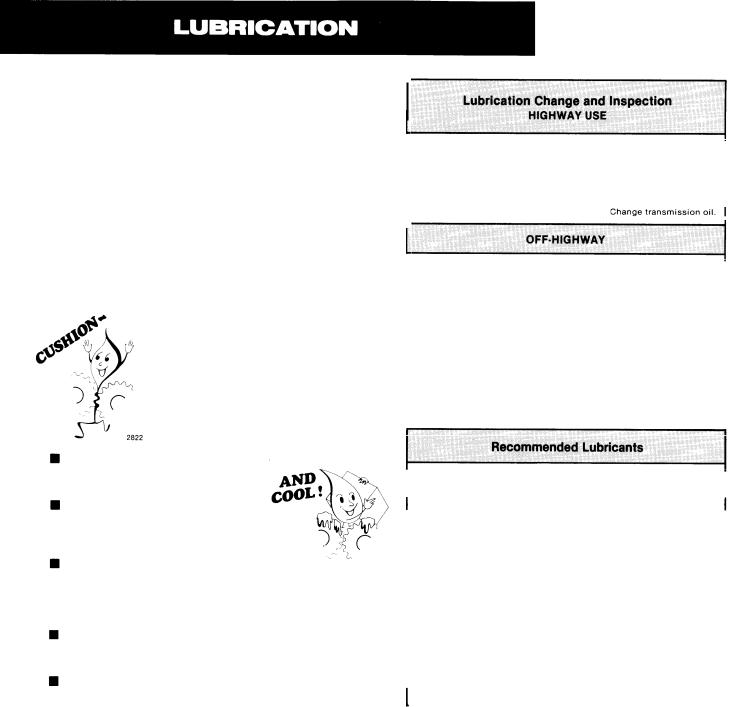
PROPER LUBRICATION . . .
THE KEY TO LONG TRANSMISSION LIFE
Proper lubrication procedures are the key to a good all-round maintenance program. If the oil is not doing its job, or if the oil level is ignored, all the maintenance procedures in the world are not going to keep the transmission running or assure long transmission life.
Oil is important, because here are some of the things it must do:
■Provide a protective film —To protect surface of heavily loaded parts such as gear teeth and bearings, thus preventing metal
to metal contact which causes scoring, scuffing and seizure.
|
First 3,000 to |
|
Change transmission oil on new units. |
I |
|
|
|
||
|
5,000 miles (4827 to 8045 Km) |
|
|
|
|
|
|
|
|
|
Every 10,000 miles (16090 Km) |
Inspect Oil Level. Check for leaks. |
I |
|
|
|
|
|
|
|
Every 50,000 miles (80450 Km) |
|
|
|
|
First 30 hours |
|
Change transmission oil on new units. |
I |
|
|
|||
|
|
|||
|
|
|
||
|
|
|
|
|
|
Every 40 hours |
|
Inspect oil level. Check for leaks. I |
|
|
Every 500 hours |
Change transmission oil where severe dirt |
|
|
|
|
conditions exist. |
|
|
|
|
|
|
|
|
|
|
|
|
|
Every 1,000 hours |
|
Change transmission oil |
|
|
|
(Normal of off-highwav use). I |
||
|
|
|
||
|
Change oil filter element, if so equipped, at each oil change, |
I |
||
|
|
|||
|
|
|
|
|
Act as a coolant—To dissipate heat.
Have sufficient fluidity—To follow, coat and cushion all loaded surfaces.
Be chemically stable—To with- |
|
stand heat and agitation with- |
2823 |
out separation, gumming-up, |
|
oxidizing or corroding. |
|
Be non-foaming—To prevent excessive foam and increased volume under severe conditions.
Be free of sediment and water—To prevent sludge and rust.
Fuller Transmissions are designed so that the internal parts operate in a bath of oil circulated by the motion of gears and shafts. Grey iron parts have built-in channels where needed, to help lubricate bearings and shafts.
Thus, all parts will be amply lubricated if these procedures are closely followed:
1.Maintain oil level. Inspect regularly.
2.Change oil regularly.
3.Use the correct grade and type of oil.
4.Buy from a reputable dealer.
I |
Type |
Grade |
Ambient |
I |
|
(SAE) |
Temperature |
||||
|
|||||
|
Heavy Duty Engine Oil |
50 |
Above 10°F. |
|
|
|
MIL-L-2104C or MIL-L-46152 |
40 |
Above 10°F. |
|
|
|
or API-SF or API-CD |
30 |
Below 10°F. |
|
|
|
|
|
|
|
|
|
Mineral Gear Oil with rust |
90 |
Above 10°F. |
|
|
|
and oxidation inhibitor |
|
|||
|
80W |
Below 10°F. |
|
||
|
API-GL-1 |
|
|||
|
|
|
|
||
|
|
|
|
|
|
I |
Mild EP Gear Oil* |
90 |
10” F. to 100°F. |
|
|
MI L-L-2105 or API-G L-4 |
80W |
-15” F. to 70°F. |
I |
||
|
|
85W140 |
Above 10°F. |
|
|
|
Multipurpose Gear Oil* |
80W140 |
Above — 15°F. |
|
|
|
90 |
10°F. to 100°F. |
|
||
|
MIL-L-2105B or MIL-L-2105C |
|
|||
|
80W90 |
— 15° F. to 100°F. |
|
||
|
or API-G L-5 |
|
|||
|
80W |
— 15°F. to 70°F. |
|
||
|
|
|
|||
|
|
75W |
— 40°F.to —150°F. |
I |
|
|
|
|
|
||
|
|
|
2824 |
||
*Mild EP gear oil or multi-purpose gear oil are not recommended when lubricant operating temperatures are above 230°F (110°C).
Do not use oil additives, friction modifiers or synthetic lubricants.
Fahrenheit to Celsius: — 40°F = — 40°C
—15°F = — 26°C 10°F = 12°C 70°F = 21°C
100°F = 38°C
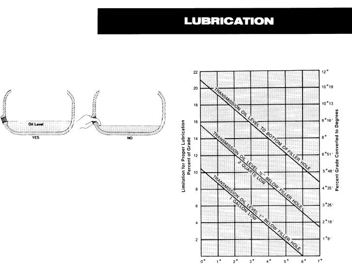
Proper Oil Level
Make sure oil is level with filler opening. Because you can reach oil with your finger does not mean oil is at proper level.
2825
Draining Oil
Drain transmission while oil is warm. To drain oil remove the drain plug at bottom of case. Clean the drain plug before re-installing.
Refilling
Clean area around filler plug and remove plug from side of case. Fill transmission to the level of the filler opening. If transmission has two filler openings, fill to level of rear opening on single countershaft models; fill to level of both openings on twin countershaft models.
The exact amount of oil will depend on the transmission inclination and model. In every instance, fill to the level of the filler opening.
Do not over fill—this will cause oil to be forced out of the case through mainshaft openings.
Adding Oil
It is recommended that types and brands of oil not be intermixed because of possible incompatibility.
Operating Temperatures
The Transmission should not be operated consistently at temperatures above 250° F (120°C). However, intermittent operating temperatures to 300” F (149°C) will not harm the transmission. Operating temperatures above 250°F increase the lubricant’s rate of oxidation and shortens its effective life. When the transmission is operated intermittently above 250” F, heavy duty engine oil provides the best oxidation resistance. When the average operating temperature is above 250°F, the transmission may require more frequent oil changes or external cooling.
The following conditions in any combination can cause operating temperatures of over 250°F:
(1) operating consistently at slow speeds, (2) high ambient temperatures, (3) restricted air flow around transmission, (4) exhaust system too close to transmission, (5) high horsepower, overdrive operation.
External oil coolers are available to r e d u c e operating temperatures when the above conditions are encountered.
Proper Lubrication Levels
Transmission Mounting Angle
2826
If the transmission operating angle is more than 12 degrees, improper lubrication can occur. The operating angle is the transmission mounting angle in the chassis plus the percent of upgrade (expressed in degrees).
The above chart illustrates the safe percent of upgrade on which the transmission can be used with various chassis mounting angles. For example: If you have a 4 degree transmission mounting angle, then 8 degrees (or 14 percent of grade) is equal to the limit of 12 degrees. If you have a O degree mounting angle, the transmission can be operated on a 12 degree (21 percent) grade.
Anytime the transmission operating angle of 12 degrees is exceeded for an extended period of time the transmission should be equipped with an oil pump or cooler kit to insure proper lubrication.
Note on the chart the effect low oil levels can have on safe operating angles. Allowing the oil level to fall 1/2“ below the filler plug hole reduces the degree of grade by approximately 3 degrees (5.5 percent).
Proper Lubrication Levels are Important!
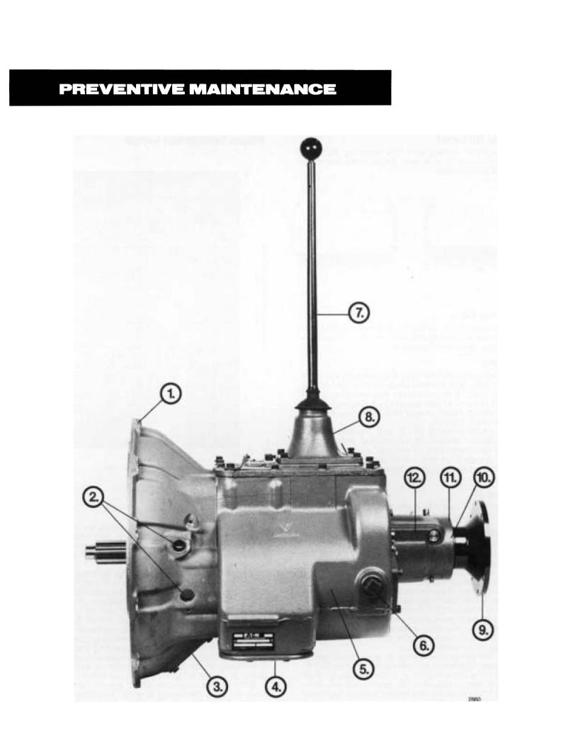
PREVENTIVE MAINTENANCE CHECK CHART
CHECKS WITHOUT PARTIAL DISASSEMBLY OF CHASSIS OR CAB
1.Clutch Housing Mounting
a.Check all capscrews in bolt circle of clutch housing for looseness.
2.Clutch Pedal Shaft and Bores
a.Pry upward on shafts to check wear.
b.If excessive movement is found, remove clutch release mechanism and check bushings in bores and wear on shafts.
3.Clutch Release Bearing
a.Remove hand hole cover and check radial and axial clearance in release bearing.
b.Check relative position of thrust surface of release bearing with thrust sleeve on push type clutches.
4.Capscrews and Gaskets
a.Check all capscrews, especially those on PTO covers and rear bearing covers for looseness which would cause oil leakage. See Torque Recommendations Section.
b.Check PTO opening and rear bearing covers for oil leakage due to faulty gasket.
5.Gear Lubricant
a.Change at specified service intervals.
b.Use only gear oils as recommended. See Lubrication Section.
6.Filler and Drain Plugs
a.Remove filler plug and check level of lubricant at specified intervals. Tighten filler and drain plugs securely.
7.Gear Shift Lever
8.Gear Shift Lever Housing A s s e m b l y
a.Remove the gear shift lever housing assembly from transmission.
b.Check tension spring and washer for set and wear.
c.Check the gear shift lever pivot or spade pin and pin slot for wear.
d.Check bottom end of gear shift Iever for wear and check slot of yokes and blocks in shift bar housing for wear at contact points with shift lever.
CHECKS WITH DRIVE LINE DROPPED
9.Universal Joint Companion Flange or Yoke Nut
a.Check for tightness. Tighten to recommended torque.
CHECKS WITH UNIVERSAL JOINT COMPANION FLANGE OR YOKE REMOVED
10.Splines on Output Shaft
a.Check for wear from movement and chucking action of the universal joint companion flange or yoke.
11.Mainshaft Rear Bearing Cover
a.Check oil seal for wear.
12.Output Shaft
a.Pry upward against output shaft to check radial clearance in mainshaft rear bearing.
a.Check for looseness and free play in housing. If lever is loose in housing, proceed with Check No. 8.

Correct torque application is extremely important to assure long transmission life and dependable performance. Over-tightening or under-tightening can result in a loose installation and, in many instances, eventually cause damage to transmission gears, shafts, and/or bearings. Use a torque wrench whenever possible to ensure proper ft.-lbs. ratings. Do not torque capscrews dry.
Recommended torque ratings, location, and thread sizes of capscrews and nuts incorporated into these transmissions are provided on the following illustrations.
|
*With Aluminum Clutch Housing. |
2861 |
|
|
|
|
|
|

I
TORQUE RECOMMENDATIONS
-- (1) OUTPUT SHAFT NUT (For Companion Flange
or Yoke),
400-450 Ft.·Lbs., Oiled at Vehicle Installation.
|
|
|
(4) GEAR SHIFT LEVER HOUSING CAPSCREWS, |
|
|
|
|
35·45Ft.·Lbs., 318·16 Threads Coated with |
|
|
|
|
Encapsulated Loctite. |
|
|
\R |
1 |
rl~'-r.A~!~$_H_AfTREAR BEARING COVER |
|
|
I |
|||
(8) COUNTERSHAFT REAR BEARING |
|
', |
|
CAPSCREWS, |
CAPSCREWS, |
COVE~'1 1 |
I 35-45 Ft.-Lbs., 318-16 Threads. |
||
( 35-45 Ft.·Lbs., 318-16 Threads. |
\ |
/ |
|
|
\ |
|
A!l |
|
|
|
|
|
O ===== l ~ ~ Threeds, Use Hydraulic |
|||
|
~ I//?-! |
o |
\LJ ~(1) SPEEDOMETER HOUSING |
||
|
|
\ |
I rilant. |
||
|
|
|
~ ~ PLUG, 35-75 Fl.·Lbs., 13116-20 |
||
|
\ft!_ . J |
~rt\\. ' |
|||
|
|
b::1 ® |
(~ ·~1 |
~ ~~ ~\ |
|
|
1' |
l\ |
~~ II _j § \ |
||
(4) CLUTCH HOUSING HAND HOLE COVER J |
I |
(6) SMALL P. T.O. COVER CAPSCREWS,~ |
CAPSCREWS, |
20-25 Ft.-Lbs., 3i8-16 Threads Coated with |
|
20-25 Ft.-Lbs., 5116-18 Threads. |
IEncapsulated Loctite. |
|
(2) REVERSE IDLER SHAFT LOCK CAPSCREWS,J |
l1) THERMOCOUPLE PLUG, |
|
25-35 Ft.-Lbs., Use Lockwashers. |
|
40-50 Ft.-Lbs., % Pipe Threads. |
2862
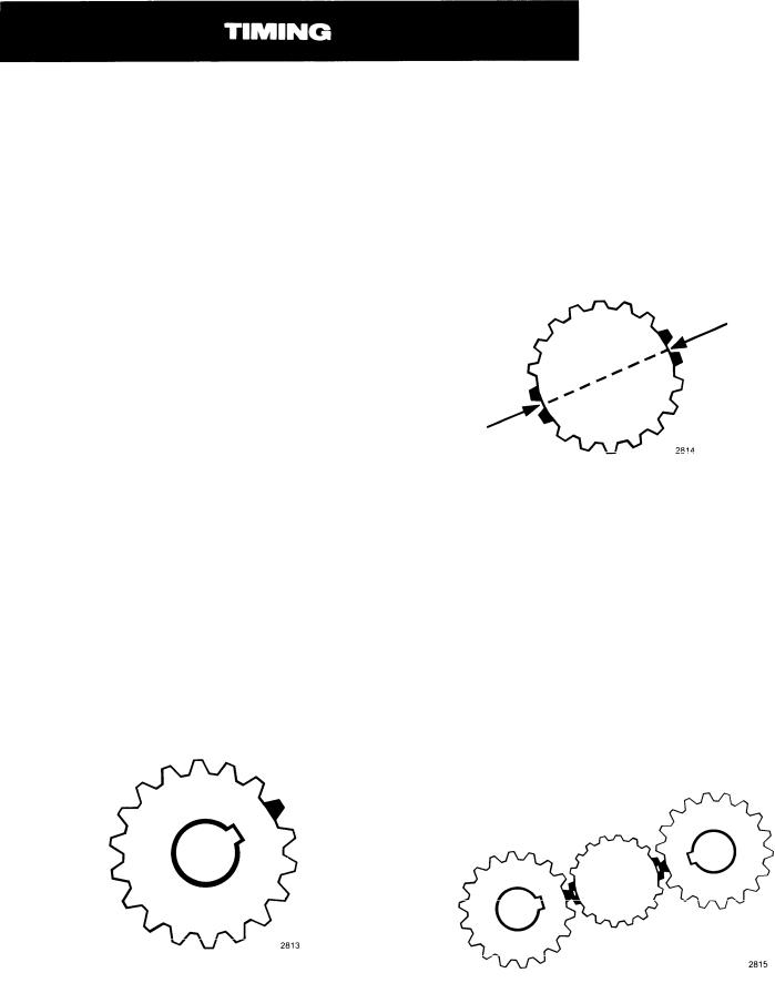
PROPER TIMING PROCEDURES
Like other Fuller twin countershaft models, the T-11605 series transmissions are “timed” at assembly. Consequently, when the rebuilding of these units is called for, it is essential that proper timing procedures are carried out during reassembly and installation. Proper timing assures that the countershaft gear teeth will come into contact with the mating mainshaft gear teeth at the same time, allowing the mainshaft gears to center on the mainshaft and split the load between the countershaft gear assemblies. If improperly timed, however, the mainshaft gears would climb out of equilibrium, resulting in unequal tooth contact between meshing gears that would lead to more serious damage occurring to the transmission later.
By design, the timing of only one set of gears is necessary—the drive gear set. It is a rather simple procedure, consisting of marking the proper teeth of the main and countershaft drive gears prior to installation of the complete assemblies in the case and meshing those marked gear teeth during assembly.
Carefully following the step-by-step procedures given here should enable even the most inexperienced persons in transmission rebuilding to successfully and properly time these units.
A.Marking countershaft drive gear teeth.
1.Prior to placing each countershaft assembly into case, clearly mark on each drive gear the gear tooth which is directly over the keyway
in gear. (See illustration A.) This tooth is stamped with an “O” to aid identification.
B.Marking main drive gear teeth.
1.Mark any two adjacent teeth on the main drive gear.
2.Mark the two adjacent teeth on the main drive gear which are directly opposite the first set marked. There should be an equal number of teeth between the markings on each side of gear. (See Illustration B.)
B.MAIN DRIVE GEAR TEETH CORRECTLY MARKED
FOR TIMING
c.Meshing marked countershaft drive gear teeth with marked main drive gear teeth. (After installing main drive gear and mainshaft assemblies, the countershaft bearings are installed to complete countershaft installation.)
1.When installing bearings on the left countershaft, mesh the marked countershaft drive gear tooth between two marked teeth on the
main drive gear. Repeat the procedure when installing the right countershaft bearings. (See Illustration C.)
A. TOOTH ON |
|
COUNTERSHAFT DRIVE GEAR |
|
DIRECTLY OVER |
C. COUNTERSHAFT DRIVE GEAR TEETH |
KEYWAY MARKED |
MESHED WITH MAIN DRIVE GEAR TEETH |
FOR TIMING |
FOR PROPER TIMING |

REMOVAL AND DISASSEMBLY
It is assumed in the detailed Removal and Disassembly instructions that the lubricant has been drained from the transmission and the unit has been removed from the chassis. Although the removal of the gear shift lever housing assembly is included in the Shifting Controls Section, this assembly must first be removed from the transmission before removing unit from the vehicle.
FOLLOW EACH PROCEDURE CLOSELY IN EACH SECTION, MAKING USE OF BOTH THE TEXT AND PICTURES.
1.BEARINGS — Carefully wash and relubricate all reusable bearings as removed and protectively wrap until ready for use. Remove bearings planned to be reused with pullers designed for this purpose.
2.ASSEMBLIES — When disassembling the various assemblies, such as the mainshaft, countershafts, and shift bar housing, lay all parts on a clean bench in the same sequence as removed. This procedure
will simplify reassembly and reduce the possibility of losing parts.
3.SNAP RINGS — Remove snap rings with pliers designed for this purpose. Snap rings removed in this manner can be reused.
4.INPUT SHAFT — The input shaft can be removed from transmission without removing the countershafts, mainshaft, or drive gear. Special procedures are required and provided in the Changing Input Shaft Section of this manual.
5.CLEANLINESS — Provide yourself with a clean place to work. It is important that no dirt or foreign material enters the unit during repairs. Dirt is an abrasive and can damage bearings. It is always good practice to clean the outside of the unit before starting the planned disassembly.
6.WHEN DRIVING — Always apply force to shafts, housings, etc., with restraint. Movement of some parts is restricted. Never apply force to the part being driven after it stops solidly. The use of soft hammers, bars and mauls for all disassembly work is recommended.
INSPECTION
Before reassembling the transmission, the individual parts should be carefully checked to eliminate those which should not be reused due to abnormal or excessive wear or damage. This inspection procedure should be carefully followed to insure the continued performance and renewed life of the rebuilt unit with the genuine Fuller parts used.
Since the cost of a new part is generally a small fraction of the total cost of downtime and labor, the reuse of a questionable part which could lead to additional repairs at a later date is not advisable. With consideration also given to the unit’s history, mileage, application, etc., good judgment stemming from product knowledge and experience can be used in determining the reuse or replacement of any transmission part.
The recommended inspection procedures are provided in the following check list:
A. BEARINGS
1.Wash all bearings in clean solvent. Check balls, rollers and raceways for pitting, discoloration, and spalled areas. Replace bearings that are pitted, discolored, or spalIed.
2.Lubricate bearings that are not pitted, discolored, or spalled and check for axial and radial clearances.
Replace bearings with excessive clearances.
3. Check bearing fits for damaged case bores. If bearing outer races spin freely in the bores, the case should be replaced.
B. GEARS
1.Check gear teeth for frosting and pitting. Frosting of gear tooth faces present little or no threat of transmission failure. Often in continued operation of the unit, frosted gears will “heal” themselves and not progress to the pitting stage. And in most cases, gears with light to moderate pitted teeth have considerable gear life remaining and can be reused. But gears with advanced stage pitting are destructive and should be replaced.
2.Check for gears with clutching teeth abnormally worn, tapered, or reduced in length from clashing in shifting. Replace gears found in any of these conditions.
3.Check axial clearance of gears. Where excessive clearance is found, check gear snap ring, washer, spacer, and gear hub for excessive wear. Maintain
.005” to .012” axial clearance on mainshaft forward
speed gears, .005” minimum on reverse gear.

INSPECTION (Cent’d.)
C. SPLINES
1. Check splines on all shafts for wear. If sliding clutch gears, companion flange, or clutch hub have worn into the sides of the splines, replace the specific shaft affected.
D. TOLERANCE/LIMIT WASHERS
1. Check surfaces of all limit washers. Washers scored or reduced in thickness should be replaced.
E.REVERSE IDLER GEAR ASSEMBLIES
1.Check bearing sleeves for wear from action of roller bearings.
F. G R A Y I R O N P A R T S
1. Check all gray iron parts for cracks and breaks. Replace or repair parts found to be damaged. Heavy castings may be welded or brazed provided the cracks do not extend into bearing bores or bolting surfaces. When doing either A.C. or D.C. welding, however, never place the ground so as to allow current to pass through the transmission.
G. CLUTCH RELEASE PARTS
1.Check clutch release parts. Replace yokes worn at cam surfaces and bearing carrier worn at contact pads.
2.Check pedal shafts. Replace those worn at bearing surfaces.
H. SHIFT BAR HOUSING ASSEMBLY
1.Check for wear on shift yokes and blocks at pads and lever slot. Replace excessively worn parts.
2.Check yokes for correct alignment. Replace sprung yokes.
3.Check Iockscrews in yokes and blocks. Tighten and re-wire those found loose.
4.If housing has been disassembled, check neutral notches of shift bars for wear from interlock balls. Bars indented at points adjacent to the neutral notch should be replaced.
L GEAR SHIFT LEVER HOUSING ASSEMBLY
1.Check spring tension on shift lever. Replace tension spring and washer if lever moves too freely.
2.If housing is disassembled, check pivot or spade pin and corresponding slot in lever for wear. Replace both parts if excessively worn.
J. BEARING COVERS
1.Check covers for wear from thrust of adjacent bearing. Replace covers damaged from thrust of bearing outer race.
2.Check bores of covers for wear. Replace those worn oversize.
K. OIL RETURN THREADS AND SEALS
1.Check oil return threads in front bearing cover. If sealing action of threads has been destroyed by contact with input shaft, replace bearing cover.
2.Check oil seal in mainshaft rear bearing cover. If sealing action of lip has been destroyed, replace seal.
L. SLIDING CLUTCHES
1.Check all shift yokes and yoke slots in sliding clutches for extreme wear or discoloration from heat.
2.Check engaging teeth of sliding clutches for partial engagement pattern.
M. FRONT BEARING COVER
1. Check inside hub of front bearing cover for wear caused by backing off of drive gear bearing nut.
N. O= RINGS
1.Check all O-rings for cracks or distortion. Replace if worn.

REASSEMBLY AND INSTALLATION
Since it is important that dirt and other foreign materials be kept out of the unit during reassembly, make sure the interiors of the case and housing are thoroughly cleaned before rebuilding begins. Dirt is an abrasive and can damage polished surfaces of bearings and washers.
Use the following precautions during reassembly and installation:
1.GASKETS — Use new gaskets throughout the transmission as it is being rebuilt. Make sure all gaskets are installed, as omission of any gasket can result in oil Ieakage or misalignment of bearing covers.
2.CAPSCREWS — TO prevent oil leakage, use thread sealant on all capscrews. For recommended torque ratings, see Torque Recommendations Section.
3.O-RINGS — Lubricate all O-rings with silicone lubricant.
4.ASSEMBLY — Refer to the illustrations provided in the Removal and Disassembly Section as a guide to reassembly.
5.INITIAL LUBRICATION — Coat all limit washers and splines of shafts with Lubriplate during reassembly to prevent scoring and galling of such
parts.
6.AXIAL CLEARANCES — Maintain original axial clearances of .005” to .012” for mainshaft forward speed gears; .005” minimum for mainshaft reverse gear.
7.BEARINGS — Use of flange-end bearing drivers are recommended for the installation of bearings. See Tool Reference Section for specific tool recommendations. These special drivers apply equal force to both bearing races, preventing damage to
balls and races while maintaining correct bearing alignment with bore and shaft.
8. UNIVERSAL JOINT COMPANION FLANGE OR YOKE — Pull the companion flange or yoke tightly into place with the mainshaft nut, using 450-500 foot-pounds of torque. Make sure the speedometer gear has been installed on yoke. If a speedometer gear is not used, a replacement spacer of the same width must be installed. Failure to pull the companion flange or yoke tightly into place will permit the output shaft to move axially with resultant damage to the rear bearing.
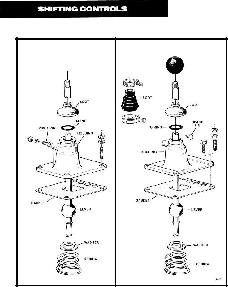
I. GEAR SHlFT LEVER HOUSING ASSEMBLY
OLD STYLE |
NEW STYLE |
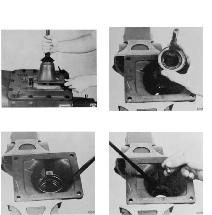
1.Install the spade pin or pivot pin, nut and washer in the bore in the housing. If previously removed, install the O-ring in the groove.
3.Remove the washer and gear shift lever from housing once the rubber boot and ball grip have been removed from lever.
2.Secure the housing in a vise and use a large screwdriver to twist between the spring and side of the housing, forcing the spring from under the three lugs. Do one coil at a time. Remove the spring.
4.Remove the spade pin or pivot pin, nut and washer from the bore in the housing. If necessary, remove the O-ring from the housing.
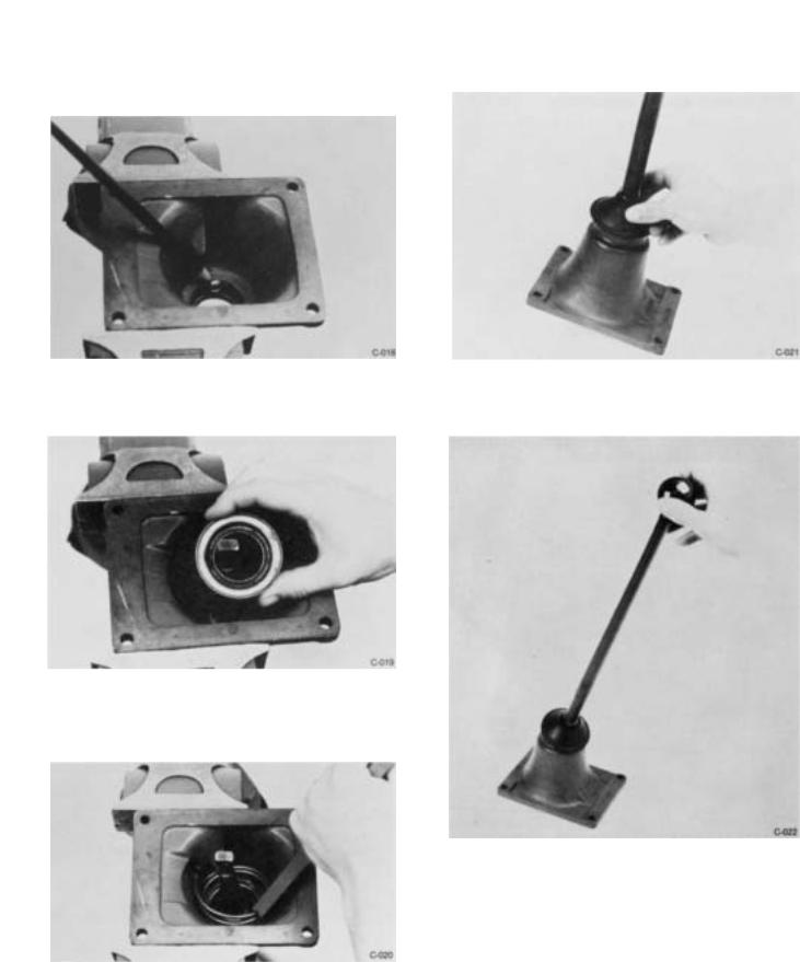
B. Reassembly
1.Install the spade pin or pivot pin, nut and washer in the bore in the housing. If previously re moved, install the O-ring in the groove.
2. With the gear shift lever positioned in housing by spade or pivot pin in lever ball slot. install the tension spring washer over the lever ball with dished-side up.
3.Seat the tension spring under the lugs in the housing, seating one coil at a time. Use of a spring driving tool is recommended.
4.Remove assembly from vise and install the rubber boot over the gear shift lever and against neck of housing.
5. Install ball grip on shift lever.
NOTE: For detailed installation instructions of gear shift lever housing assembly on shift bar housing assembly, see Reassembly and Installation Section, Part III-B, of this manual.
Il. SHIFT BAR HOUSING ASSEMBLY
A. Removal and Disassembly
1. Turn out the attaching capscrews.
2.Jar to break the gasket seal and lift the shift bar housing from transmission.
NOTE: During disassembly, lay all parts on a clean bench in the order in which they are removed to facilitate reassembly. Keep bars not being removed in the neutral position or interlock parts will lock bars.
 Loading...