


AT-1202

Service Manual
Eaton Fuller Heavy-Duty
Transmissions
TRSM0996 EN-US
June 2008
AT-1202 Models

For parts or service call us
Pro Gear & Transmission, Inc.
1 (877) 776-4600
(407) 872-1901
parts@eprogear.com
906 W. Gore St.
Orlando, FL 32805
Specifications
Warnings and Precautions
Before starting a vehicle always be seated in the driver’s seat, place the transmission in neutral, set the parking brakes and
disengage the clutch.
Before working on a vehicle place the transmission in neutral, set the parking brakes and block the wheels.
Before towing the vehicle place the transmission in neutral, and lift the rear wheels off the ground, remove the axle shafts,
or disconnect the driveline to avoid damage to the transmission during towing.
The description and specifications contained in this service publication are current at the time of printing.
Eaton Corporation reserves the right to discontinue or modify its models and/or procedures and to change specifications at any
time without notice.
Any reference to brand name in this publication is made as an example of the types of tools and materials recommended for use
and should not be considered an endorsement. Equivalents may be used.
This symbol is used throughout this manual to call attention to procedures where carelessness or failure to follow
specific instructions may result in personal injury and/or component damage.
Departure from the instructions, choice of tools, materials and recommended parts mentioned in this publication may jeopardize
the personal safety of the service technician or vehicle operator.
Warning: Failure to follow indicated procedures creates a high risk of personal injury to the servicing technician.
Caution: Failure to follow indicated procedures may cause component damage or malfunction.
Note: Additional service information not covered in the service procedures.
General Information
Tip: Helpful removal and installation procedures to aid in the service of this unit.
Always use genuine Eaton replacement parts.
1

Introduction
Description
The AT-1202 model is a two-speed, twin countershaft auxiliary transmission designed primarily for use with heavy-duty transmissions.
This auxiliary transmission contains two sets of gears, thus giving the reduction (low) ratio when power is delivered through these
two sets of gears. The other speed is obtained by direct (high) drive through the auxiliary. A single shift bar in the right side of the
case controls speed changes.
2
Shift Positions and Specifications
Direct
Specifications
Shift Positions
Nuetral
Reduction
General Information
Specifications
Gear Ratios
Gear Ratios
Direct 1.00
Reduction 2.036
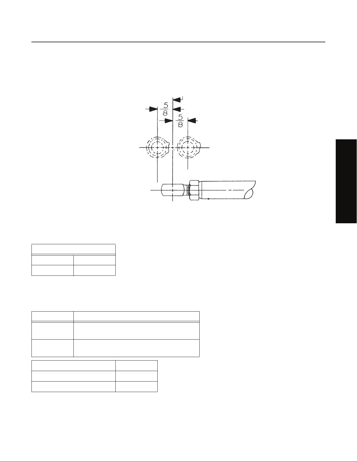
Mountings
Front bearing cover machined for trunnion mounting.
Four 5/8" diameter mounting studs, two on each side of case.
Power Take-OFF
Bottom SAE Standard 6-bolt, 30 tooth, 5P gear on left coun-
tershaft turning at .993 input shaft speed.
Top SAE Standard 8-bolt, 30 tooth, 5P gear on right coun-
tershaft turning at .993 input shaft speed.
Weight 330 pounds
Oil Capacity 12 pints
Installation length 16-3/16 inches
3

Lubrication
Lubrication Specifications
Note: For a list of Eaton Approved Synthetic Lubricants, see TCMT-0021 the list of approved lubricants and TCMT-0021 the list of
lube intervals, or call 1-800-826-HELP (4357). Recommended lubricants for the 2-A-92 are currently the E500 and the E250,
which list a mileage, a year, and a hour change interval.
Note: The use of lubricants not meeting these requirements will affect warranty coverage.
Note: Additives and friction modifiers must not be introduced.
Note: Never mix engine oils and gear oils in the same transmission.
Buy from a reputable dealer
For a complete list of approved and reputable dealers, write to: Eaton Corporation, Worldwide Marketing Services, P.O. Box 4013,
Kalamazoo, MI 49003
Transmission Operating Angles
If the transmission operating angle is more than 12 degrees, improper lubrication will occur. The operating angle is the transmission mounting angle in the chassis plus the percent of upgrade (expressed in degrees). For operating angles over 12 degrees, the
transmission must be equipped with an oil pump or cooler kit to insure proper lubrication.
Mixing of Oil Types
CAUTION: Never mix engine oils & gear oils in the same transmission.
Engine oils and gear oils may not be compatible; mixing can cause breakdown of the lubricant and affect component performance.
When switching between types of lubricants, all areas of each affected component must be thoroughly flushed.
Operating Temperature
Oil Coolers
Kit K-1702 includes the pump, cooler and accesories to convert the AT-1202.
4

Maintenance
Preventative Maintenance Check List
The following maintenance checks can be made without removing the transmission from the chassis. Items 1 through 5 can be
performed without any prior mechanical work; items 6 through 8 require the dropping of the output driveline and the input driveline where possible.
1. Oil Leaks
• Make visual checks for oil leakage from mainshaft openings, gaskets at bearing covers, top cover, and from front rear
shifting bar bores. Check drain plugs for losseness.
2. Gear Lubricant
• Remove filler plug in right side and check oil level at regular service intervals.
• Change oil at specified intervals, using grade and type recommended.
Note: See Lubrication section for inspection, oil type, grade, and oil capacity.
3. Gear Shift Lever and Linkage
• Check the auxiliary gear shift lever for wear at mounting.
• Check shifting linkage for wear and looseness.
• Check to make sure exact neutral position of auxiliary gear shift lever corresponds to neutral position of auxiliary shifting
bar.
General Information
4. Capscrews and Nuts
• Check capscrews in top cover and bearing covers for looseness which might be the cause of oil leakage.
• Check nuts on rear support bracket or plate for looseness.
5. Mountings
• Check mounting bolts and nuts for looseness.
6. Universal Joint Companion Flange Retaining Nuts
• With output driveline dropped, and front driveline dropped, where possible, check nuts for looseness. Tighten to recommended torque.
7. Splines on Shafts
• Check input and output shafts for wear from movement and chucking action of universal joint companion flange.
8. Mainshaft Rear Bearing
• Pry upward against output shaft to check radial clearance of mainshaft rear bearing.
5

Tools
Tool Reference
Some illustrations in this manual show the use of specialized maintenance tools. These tools are recommended for transmission
repair as they make repair easier, faster, and prevent costly damage to such critical parts as bearings and sleeves.
Listed below are charts which list these specialized tools, the tool name and how it can be obtained.
General Tools
Tool Purpose
0-100 lbs.ft. 1/2" drive Torque Wrench General torquing of fasteners.
0-600 lbs.ft. 3/4" or 1" drive Torque Wrench Torquing of output nut.
Snap Ring Pliers - large standard external To remove snap rings at the auxiliary drive gear, input shaft
bearing, and countershaft.
Rolling Head (Crow’s foot) prybar To remove the auxiliary drive gear bearing.
Aftermarket Tools
Tool Purpose Eaton Part Number
Seal Driver Kit To install seal K-2413
Special Tools
Reference Number Tool Purpose G and W Tool Number Great Lakes Tool Num-
ber
Seal Driver Used to install the oil
seals in the front and
rear bearing cover
housings.
Bearing Driver Used to install the input
shaft and output shaft
bearings.
Bearing Driver Used to install the
countershaft bearings.
Specialty Tool Manufacturers
Below are the addresses and phone numbers of the companies that make tools specifically for Eaton®Fuller® transmissions:
G and W Tool Company
1105 E. Louisville, Broken Arrow, OK 74012-5724, Phone: 800-247-5882, or 918-258-6881
Great Lakes Tool
8530 M-89, Richland, MI 49083, Phone: 800-877-9618, or 269-629-9628
G-112
6

Torque
Torque Ratings
Recommended torque ratings, location and thread sizes of capscrews and nuts are listed below. Capscrew lengths are given for
reference purposes as a guide for installation at proper locations.
Correct torque application is extremely important to assure long transmission life and dependable performance. Over-tightening
or undertightening can result in a loose installation and in many instances, cause damage to transmission gears, shafts and bearings. Do not torque capscrews dry.
Capscrews
Location Quantity Thread Size and Length Torque Rating Foot-Pounds
PTO cover, large 8 7/16 - 14x 1 50 - 65 lbs. ft.
PTO cover, small 6 3/8 - 16x 3/4 18-23 lbs. ft. (12-15 lbs. ft.
with oil filter)
General Information
Countershaft Front Bearing
Covers
Countershaft Rear Bearing
Covers
Rear Plate to Front Case 16 3/8 - 16x 1 - 1/2
Rear Bearing Housing 5 3/8 - 16x 3
Shift Bar Housing 4 3/8 - 16x 1 - 1/4
83/8 - 16x 1
83/8 - 16x 3
1 3/8 - 16x 3 35-45 lbs. ft.
23/8 - 16x 2
1 3/8 - 16x 3 eslock
Nuts
Location Quantity Thread Size and
Length
Mounting Studs 4 5/8 - 18 170 - 185
Front Bearing
Housing
Companion
Flanges or
Yokes
61/2 - 20
2 2 3/4 - 16 450 - 500
Torque Rating
Note: Installing the capscrews with more than 23 lbs. ft. of torque will force the corners of the PTO cover away from the case with
resultant oil leakage.
7
Removal and Disassembly
General Instructions for Disassembly
Important: Read this section before starting the detailed disassembly procedures.
It is assumed in the detailed disassembly instructions that the transmission has been removed from the chassis, the lubricant has
been drained, the parking brake removed, if so equipped, and both universal joint companion flanges have been removed.
Follow each procedure closely in each section, making use of both the text and pictures. Use certain precautions, as listed below,
during disassembly.
Cleanliness
• Provide a clean place to work. It is important that no dirt or foreign material enters the unit during repairs. The outside
of the unit should be carefully cleaned before starting the disassembly. Dirt is abrasive and can damage highly polished
parts such as bearings, sleeves, and bushings.
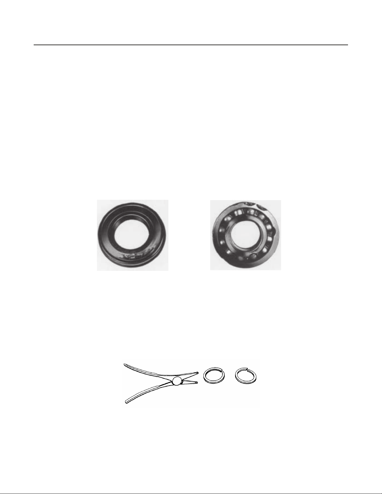
Bearings
• Carefully wash and re-lubricate all bearings as removed and protectively wrap until ready for use. Remove all bearings
with pullers designed for this purpose. Do not remove bearings with hammer and punch.
Bearing removed with punch,
damaged shield.
When Driving
• Apply force to shafts, bearings, and housings with restraint. Movement of some parts is restricted. Do not apply force
after the part being driven stops solidly. Use soft hammers, soft bars, and mauls for all disassembly work.
Snap Rings
• Remove snap rings with pliers designed for this purpose. Rings removed in this manner may be reused.
Bearing removed with
chisel, damaged outer race.
8
How to Remove the Companion Flanges or Yokes
Special Instructions
None
Special Tools
• Typical service tools
Procedure -
Removal and Disassembly
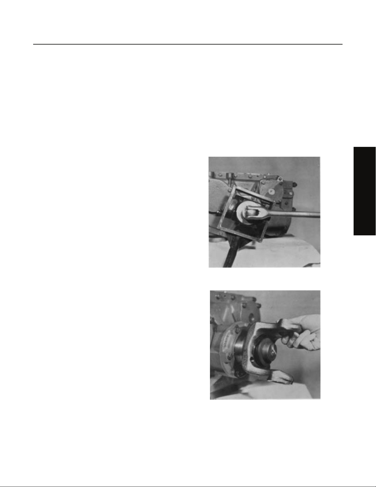
1. Brace against the yoke or flange on each shaft and use a
large breaker bar to remove the elastic stop nut from each
shaft.
2. Remove the washer and flange or yoke from each shaft.
Note: If a special tool is not available, the stop nuts may be
removed by putting the transmission in direct gear,
installing a breaker bar on the stop nut of both input
and output shaft and removing the nuts by bracing
them against each other.
Removal and Disassembly
9

Removal and Disassembly
How to Remove the Rear Plate from the Front Case
Special Instructions
None
Special Tools
• Typical service tools
Procedure -
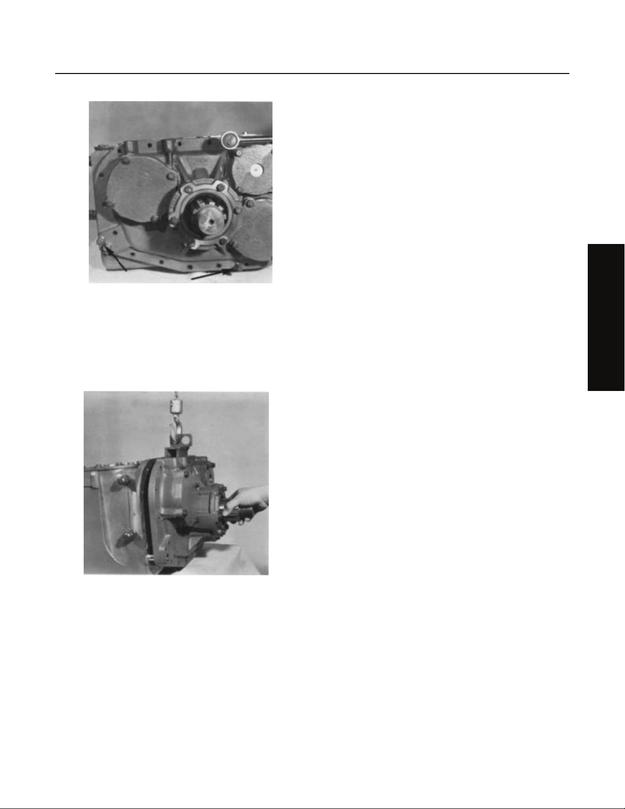
1. Loosen the jam nut and turn the rod end from the end of the
shift bar.
2. Turn out the 19 capscrews attaching the rear plate to the
front case.
10
Removal and Disassembly
3. Insert three puller screws in the three tapped holes in the
mounting flange of the rear approximately 1/2 to break the
gasket.
4. Attach a chain hoist to the rear plate and move the plate
evenly to the rear and off the front case dowel pins. Mount
the rear plate in a vise in the upright position.
Removal and Disassembly
11
Removal and Disassembly
14
2
12
1
13
7
6
3
4
5
9
8
15
10
11
16
61
61
17
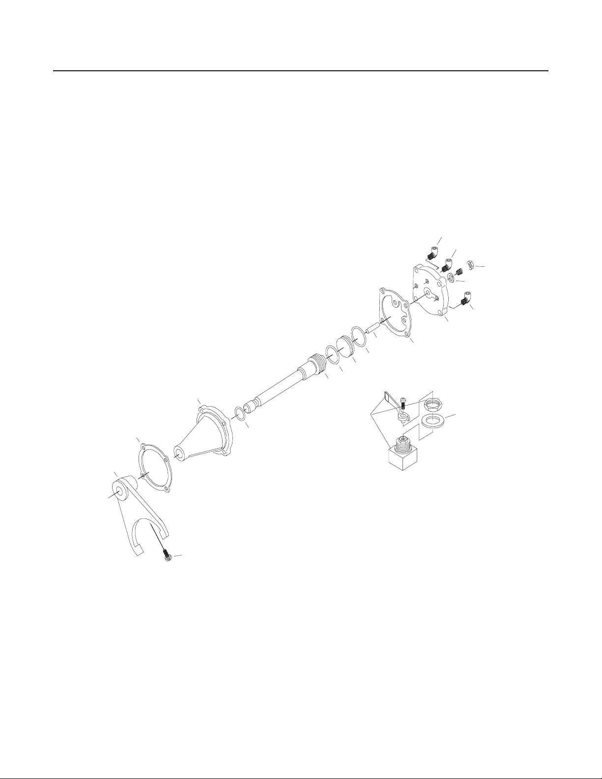
How to Remove the Shifting Control Assembly With Air
Special Instructions
None
Special Tools
• Typical service tools
1. O-ring
2. Shift Cylinder
3. Shift Piston Assembly
4. O-ring
5. Roll Pin
6. O-ring
7. Yoke Bar
8. Cylinder Cover
9. Gasket
11. Capscrew
12. Shift Yoke
13. Lockscrew
14. Gasket
15. Elbow
16. Air Valve
17. Air Valve
18. Valve Plate
10. Lockwasher
12

Removal and Disassembly
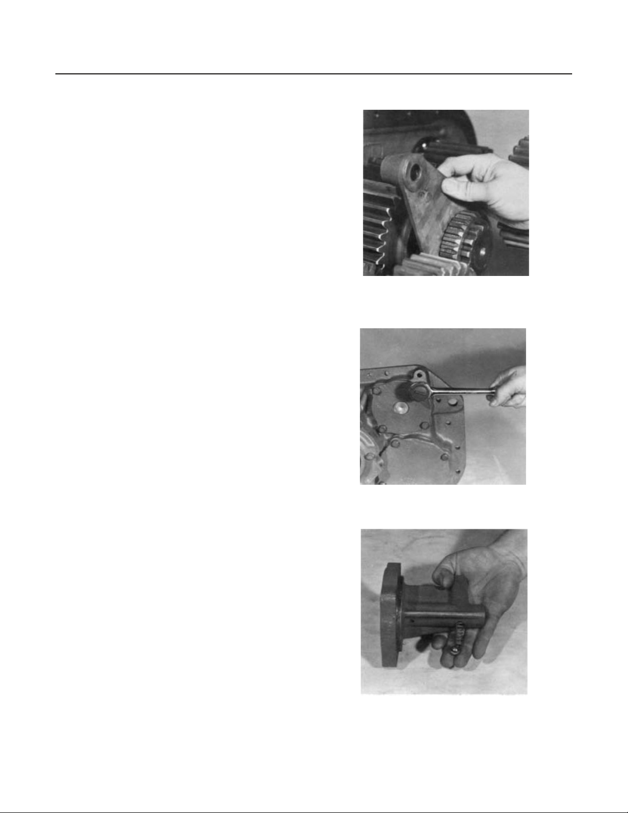
Procedure -
1. Cut the lockwire and remove the yoke lockscrew.
2. Remove the spacer from the front of the shift bar.
Removal and Disassembly
3. Put a rag over the bore in the shift bar housing to prevent
loss of the tension spring and ball and pull the shift bar
sharply forward and from the housing.
13
Removal and Disassembly
4. Remove the yoke from the sliding clutch and remove the
sliding clutch from the splines of the output shaft.
5. Turn out the four capscrews attaching the shift bar housing
to the rear plate and remove the housing.l
6. Tip the housing to remove the tension spring and ball.
14
Removal and Disassembly
1
2
3
4
5
13
7
8
10
9
11
6
12
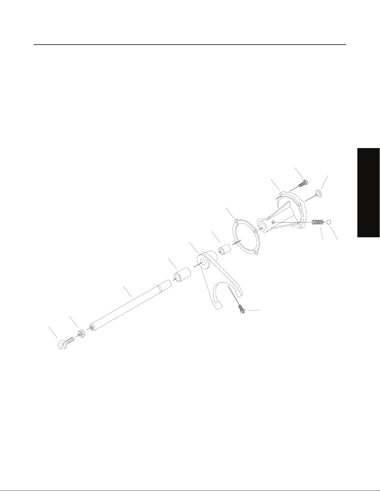
How to Remove the Shifting Control Assembly Without Air
Special Instructions
None
Special Tools
• Typical service tools
Removal and Disassembly
10
1. Eye Rod end
2. Nut
3. Yoke Bar
4. Spacer
5. Shift Yoke
6. Lockscrew
7. Gasket
8. Shift Cylinder
13
11
12
9. Plug
10. Capscrew
11. Spring
12. Steel Ball
13. NLA-Spacer
15

Removal and Disassembly
Procedure -
1. Cut the lockwire and remove the yoke lockscrew.
2. Remove the spacer from the front of the shift bar.
3. Put a rag over the bore in the shift bar housing to prevent
loss of the tension spring and ball and pull the shift bar
sharply forward and from the housing.
4. Remove the yoke from the sliding clutch and remove the
sliding clutch from the splines of the output shaft.
16
 Loading...