


 Loading...
Service Manual
Fuller Automated Transmissions
TRSM0062
October 2007
FO-6406A-ASW FO-6406A-ASX FO-8406A-ASW FO-8406A-ASX RT-14910B-AS2 RTLO-14918A-AS2 RTLO-16918A-AS2 RTLO-18918A-AS2 RTLO-20918A-AS2 RTLO-22918A-AS2 RTO-10710B-AS2 RTO-10910B-AS2 RTO-10910B-DM2 RTO-12710B-AS2 RTO-12910B-AS2 RTO-12910B-DM2 RTO-14710B-AS2 RTO-14710C-AS2
RTO-14910B-AS2 RTO-14910B-DM2 RTO-14910C-AS2 RTO-16710C-AS2 RTO-16910B-AS2 RTO-16910B-DM2 RTO-16910C-AS2 RTO-18910B-AS2

General Information
Cautions, and Warnings
 WARNING
Follow the specified procedures in the indicated order to avoid personal injury.
 CAUTION
Follow the specified procedures in the indicated order to avoid equipment malfunction or damage
Note: Additional relevant information not covered in the service procedure.
 IMPORTANT
For additional information and assistance, call the Roadranger Help Desk at 1-800-826-HELP (4357). Mexico: 01-800-826-HELP (4357). You may also find more information at www.Roadranger.com.
Operational Warnings
Before starting a vehicle:
1.Sit in the driver’s seat.
2.Place the Shift Lever in neutral.
3.Set the parking brake.
4.Disengage the clutch.
Before working on the vehicle or leaving the cab with the engine running:
5.Place the shift lever in neutral.
6.Set the parking brake.
7.Block the wheels.
Do not release the parking brake or attempt to select a gear until the air pressure is at the correct level.
When parking the vehicle or leaving the cab:
8.Place the shift lever in neutral.
9.Set the parking brake.
Do not operate the vehicle if the alternator lamp is lit or if the gauges indicate low voltage.
Repair Warnings
When disassembling various assemblies, lay all parts on a clean bench in the same sequence as removed to simplify and reduce the possibility of losing parts.
Disconnect the vehicle’s battery before removing or installing electronic parts.
Since the cost of a new part is generally a small fraction of the cost of downtime and labor, avoid reusing a questionable part that could lead to additional repairs and expense.
Use of other than recommended tools, parts, and instructions listed in this manual may place the safety of the service technician or vehicle driver in jeopardy.
The location of some components may vary with each OEM.
The removal and installation procedure described for each component may vary for your vehicle.
Always use genuine Eaton replacement parts. For a complete list of approved and reputable dealers, write to:
Eaton Corporation
Truck Component Marketing Headquarters
P.O. Box 4013
Kalamazoo, MI 49003
Every effort has been made to ensure the accuracy of the information contained in this manual. However, Eaton Corporation makes no warranty, expressed or implied, based on the information provided.

Table of Contents
General Information |
|
Preventive Maintenance |
|
Service Procedures |
|
Cautions, and Warnings ............................................................................................................................................ |
i |
How to Use This Manual ......................................................................................................................................... |
1 |
Dry Clutch Models Only .......................................................................................................................................... |
3 |
UltraShift™ HP Models ............................................................................................................................................ |
9 |
Lubricant Filter (UltraShift HP Models Only) – Remove ........................................................................................ |
15 |
Lubricant Filter (UltraShift HP Models Only) – Install ............................................................................................ |
17 |
Rail Select Sensor – Remove ................................................................................................................................ |
19 |
Rail Select Sensor – Install ................................................................................................................................... |
21 |
Gear Select Sensor – Remove ............................................................................................................................... |
23 |
Gear Select Sensor – Install .................................................................................................................................. |
25 |
Input Shaft Speed Sensor – Remove .................................................................................................................... |
27 |
Input Shaft Speed Sensor – Install ........................................................................................................................ |
29 |
Main Shaft Speed Sensor – Remove ..................................................................................................................... |
31 |
Main Shaft Speed Sensor – Install ........................................................................................................................ |
33 |
Output Shaft Speed Sensor – Remove .................................................................................................................. |
35 |
Output Shaft Speed Sensor – Install ..................................................................................................................... |
37 |
Range Valve – Remove ......................................................................................................................................... |
39 |
Range Valve – Install ............................................................................................................................................. |
41 |
Splitter Valve – Remove ........................................................................................................................................ |
43 |
Splitter Valve – Install ........................................................................................................................................... |
45 |
Air Filter/Regulator – Remove ............................................................................................................................... |
47 |
Air Filter/Regulator – Install .................................................................................................................................. |
49 |
Inertia Brake (6-Speed) – Remove ........................................................................................................................ |
51 |
Inertia Brake (6-Speed)– Install ............................................................................................................................ |
53 |
Inertia Brake (7, 10, and 18-Speed) – Remove ..................................................................................................... |
55 |
Inertia Brake (7, 10, and 18 Speed) – Install ......................................................................................................... |
57 |
Inertia Brake Relocation Instructions 8 to 6 Bolt PTO Opening--Remove .............................................................. |
59 |
Inertia Brake Relocation Instructions 8 to 6-Bolt PTO opening--Install ................................................................. |
61 |
Electric Shifter – Remove ...................................................................................................................................... |
63 |
Electric Shifter – Install ......................................................................................................................................... |
65 |
Transmission Controller – Remove ....................................................................................................................... |
67 |
Transmission Controller – Install .......................................................................................................................... |
69 |
Transmission Harness – Remove .......................................................................................................................... |
71 |
Transmission Harness – Install ............................................................................................................................. |
73 |
Gear Display – Remove ......................................................................................................................................... |
75 |
Gear Display – Install ............................................................................................................................................ |
77 |
Shift Control– Remove .......................................................................................................................................... |
79 |
Shift Control – Install ............................................................................................................................................ |
81 |
Transmission – Remove ....................................................................................................................................... |
83 |
Transmission – Install ........................................................................................................................................... |
84 |
Change Control Log .............................................................................................................................................. |
85 |
Contents of Table
ii
General Information
How to Use This Manual
This manual is designed to provide detailed information necessary to service and repair the Automation portion of the following Fuller transmissions:
1.6-Speed (Fx-x406x-ASX, Fx-x406x-ASW)
2.7-Speed (TO-xx607x-ASX)
3.10-Speed (RTO-xxx10x-AS2, RTO-xxx10x-DM2)
4.18-Speed (RTLO-xx918x-AS2)
The service procedures in this manual are for transmission automation components only. To locate the information you need, simply locate the procedure in the index, turn to the page specified, and follow the procedure.
To service the mechanical portion of the transmission system, refer to the specific transmission service manual.
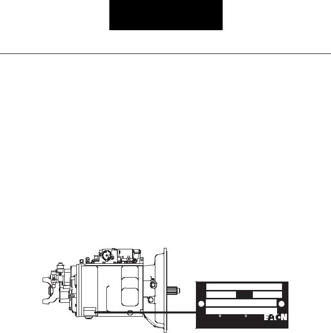
Serial Tag Information and Model Nomenclature
Transmission model designation and other transmission identification information are stamped on the serial tag. To identify the transmission model and serial number, locate the tag on the transmission and then locate the numbers as shown.
Model RTO-14710B-AS2 |
|
|
Serial |
Made In |
|
Eaton R Fuller R |
Eaton Corporation |
|
Transmissions |
|
Transmission Div. |
|
|
Kalamazoo, MI. 49003 |
1

For parts or service call us Pro Gear & Transmission, Inc.
1(877) 776-4600
(407)872-1901 parts@eprogear.com
906 W. Gore St. Orlando, FL 32805

General Information
Model Number
The model number gives basic information about the transmission and is explained below. Use this number when calling for service assistance or replacement parts.
6-Speed |
|
|
|
|
|
|
|
|
F |
O - 8 4 0 6 A - A S X |
|
|
|
|
|
|
|
|
||||||||||||||||||||||||||||||||||||||||||||||||
|
|
|
|
|
|
|
|
|
|
|
|
|
|
|
|
|
|
|
||||||||||||||||||||||||||||||||||||||||||||||||
|
|
Fuller |
|
|
|
|
|
|
|
|
|
|
|
|
|
|
|
|
|
|
|
|
|
|
|
|
|
|
|
|
|
|
|
|
|
|
|
|
|
|
|
|
|
|
|
|
|
|
|
|
|
|
|
|
|
|
W-WetClutch |
|||||||||
|
|
|
|
|
|
|
|
|
|
|
|
|
|
|
|
|
|
|
|
|
|
|
|
|
|
|
|
|
|
|
|
|
|
|
|
|
|
|
|
|
|
|
|
|
|
|
|
|
|
|
|
|
|
|
|
X-Inertia Brake |
||||||||||
|
|
|
|
|
|
|
|
|
|
|
|
|
|
|
|
|
|
|
|
|
|
|
|
|
|
|
|
|
|
|
|
|
|
|
|
|
|
|
|
|
|
|
|
|
|
|
|
|
|
|
|
|
|
|
|
|||||||||||
|
|
|
|
|
|
|
|
|
|
|
|
|
|
|
|
|
|
|
|
|
|
|
|
|
|
|
|
|
|
|
|
|
|
|
|
|
|
|
|
|
|
|
|
|
|
|
|
|
|
|
|
|
|
|
|
|
|
|
|
|
|
|
|
|
|
|
Overdrive |
|
|
|
|
|
|
|
|
|
|
|
|
|
|
|
|
|
|
|
|
|
|
|
|
|
|
|
|
|
|
|
|
|
|
|
|
|
|
|
|
|
|
|
|
|
|
|
|
|
|
|
AutoShift |
||||||||||||||
|
|
|
|
|
|
|
|
|
|
|
|
|
|
|
|
|
|
|
|
|
|
|
|
|
|
|
|
|
|
|
|
|
|
|
|
|
|
|
|
|
|
|
|
|
|
|
|
|
|
|||||||||||||||||
Torque x 100 |
|
|
|
|
|
|
|
|
|
|
|
|
|
|
|
|
|
|
|
|
|
|
|
|
|
|
|
|
|
|
|
|
|
|
|
|
|
|
|
|
|
|
|
|
|
|
|
|
|
|
|
Gear Ratio |
||||||||||||||
|
|
|
|
|
|
|
|
|
|
|
|
|
|
|
|
|
|
|
|
|
|
|
|
|
|
|
|
|
|
|
|
|
|
|
|
|
|
|
|
|
|
|
|
|
|
|
|
|
|
|
||||||||||||||||
Design Level |
|
|
|
|
|
|
|
|
|
|
|
|
|
|
|
|
|
|
|
|
|
|
|
|
|
|
|
|
|
|
|
|
|
|
|
|
|
|
|
|
|
|
|
|
|
|
|
|
|
Forward Speeds |
||||||||||||||||
|
|
|
|
|
|
|
|
|
|
|
|
|
|
|
|
|
|
|
|
|
|
|
|
|
|
|
|
|
|
|
|
|
|
|
|
|
|
|
|
|
|
|
|
|
|
|
|
|
||||||||||||||||||
7-Speed |
|
|
|
|
|
|
|
|
T |
|
O - 1 1 6 0 7 B - A S X |
|
|
|
|
|
|
|
||||||||||||||||||||||||||||||||||||||||||||||||
|
|
|
|
|
|
|
|
|
|
|
|
|
|
|
|
|
|
|||||||||||||||||||||||||||||||||||||||||||||||||
Twin Countershaft |
|
|
|
|
|
|
|
|
|
|
|
|
|
|
|
|
|
|
|
|
|
|
|
|
|
|
|
|
|
|
|
|
|
|
|
|
|
|
|
|
|
|
|
|
|
|
|
|
|
|
|
|
X - Inertia Brake |
|||||||||||||
|
|
|
|
|
|
|
|
|
|
|
|
|
|
|
|
|
|
|
|
|
|
|
|
|
|
|
|
|
|
|
|
|
|
|
|
|
|
|
|
|
|
|
|
|
|
|
|
|
|
|
|
|||||||||||||||
Overdrive |
|
|
|
|
|
|
|
|
|
|
|
|
|
|
|
|
|
|
|
|
|
|
|
|
|
|
|
|
|
|
|
|
|
|
|
|
|
|
|
|
|
|
|
|
|
|
|
|
|
|
|
|
|
|||||||||||||
|
|
|
|
|
|
|
|
|
|
|
|
|
|
|
|
|
|
|
|
|
|
|
|
|
|
|
|
|
|
|
|
|
|
|
|
|
|
|
|
|
|
|
|
|
|
|
|
|
|
|
|
AutoShift |
||||||||||||||
|
|
|
|
|
|
|
|
|
|
|
|
|
|
|
|
|
|
|
|
|
|
|
|
|
|
|
|
|
|
|
|
|
|
|
|
|
|
|
|
|
|
|
|
|
|
|
|
|
|
|
|
|||||||||||||||
Torque x 100 |
|
|
|
|
|
|
|
|
|
|
|
|
|
|
|
|
|
|
|
|
|
|
|
|
|
|
|
|
|
|
|
|
|
|
|
|
|
|
|
|
|
|
|
|
|
|
|
|
|
|
|
|
|
|
|
|||||||||||
|
|
|
|
|
|
|
|
|
|
|
|
|
|
|
|
|
|
|
|
|
|
|
|
|
|
|
|
|
|
|
|
|
|
|
|
|
|
|
|
|
|
|
|
|
|
|
|
|
|
|
|
Gear Ratio |
||||||||||||||
|
|
|
|
|
|
|
|
|
|
|
|
|
|
|
|
|
|
|
|
|
|
|
|
|
|
|
|
|
|
|
|
|
|
|
|
|
|
|
|
|
|
|
|
|
|
|
|
|
|
|
|
|||||||||||||||
Design Level |
|
|
|
|
|
|
|
|
|
|
|
|
|
|
|
|
|
|
|
|
|
|
|
|
|
|
|
|
|
|
|
|
|
|
|
|
|
|
|
|
|
|
|
|
|
|
|
|
|
|
|
|
|
|
|
|
||||||||||
|
|
|
|
|
|
|
|
|
|
|
|
|
|
|
|
|
|
|
|
|
|
|
|
|
|
|
|
|
|
|
|
|
|
|
|
|
|
|
|
|
|
|
|
|
|
|
|
|
|
|
|
Forward Speeds |
||||||||||||||
|
|
|
|
|
|
|
|
|
|
|
|
|
|
|
|
|
|
|
|
|
|
|
|
|
|
|
|
|
|
|
|
|
|
|
|
|
|
|
|
|
|
|
|
|
|
|
|
|
|
|
|
|||||||||||||||
10-Speed |
|
|
R |
|
T O - 1 4 7 1 0 B - A S 2 |
|
|
|||||||||||||||||||||||||||||||||||||||||||||||||||||||||||
|
|
|
|
|
|
|
|
|
|
|||||||||||||||||||||||||||||||||||||||||||||||||||||||||
|
|
|
|
|
|
|
|
|
|
|
|
|
||||||||||||||||||||||||||||||||||||||||||||||||||||||
Roadranger |
|
|
|
|
|
|
|
|
|
|
|
|
|
|
|
|
|
|
|
|
|
|
|
|
|
|
|
|
|
|
|
|
|
|
|
|
|
|
|
|
|
|
|
|
|
|
|
|
|
|
|
|
|
|
|
|
|
|
2 - AutoShift II |
|||||||
|
|
|
|
|
|
|
|
|
|
|
|
|
|
|
|
|
|
|
|
|
|
|
|
|
|
|
|
|
|
|
|
|
|
|
|
|
|
|
|
|
|
|
|
|
|
|
|
|
|
|
|
|
|
|
|
|
|
|||||||||
Twin Countershaft |
|
|
|
|
|
|
|
|
|
|
|
|
|
|
|
|
|
|
|
|
|
|
|
|
|
|
|
|
|
|
|
|
|
|
|
|
|
|
|
|
|
|
|
|
|
|
|
|
|
|
|
|
|
|
|
|
|
|
(Second Generation) |
|||||||
|
|
|
|
|
|
|
|
|
|
|
|
|
|
|
|
|
|
|
|
|
|
|
|
|
|
|
|
|
|
|
|
|
|
|
|
|
|
|
|
|
|
|
|
|
|
|
|
|
|
|
|
|
|
|
|
|
|
|||||||||
|
|
|
|
|
|
|
|
|
|
|
|
|
|
|
|
|
|
|
|
|
|
|
|
|
|
|
|
|
|
|
|
|
|
|
|
|
|
|
|
|
|
|
|
|
|
|
|
|
|
|
|
|
|
|
|
|
|
|
|
|
||||||
Overdrive |
|
|
|
|
|
|
|
|
|
|
|
|
|
|
|
|
|
|
|
|
|
|
|
|
|
|
|
|
|
|
|
|
|
|
|
|
|
|
|
|
|
|
|
|
|
|
|
|
|
|
|
|
|
|
|
|
|
|
|
AutoShift |
||||||
|
|
|
|
|
|
|
|
|
|
|
|
|
|
|
|
|
|
|
|
|
|
|
|
|
|
|
|
|
|
|
|
|
|
|
|
|
|
|
|
|
|
|
|
|
|
|
|
|
|
|
|
|
|
|
|
|
|
|
||||||||
Torque x 100 |
|
|
|
|
|
|
|
|
|
|
|
|
|
|
|
|
|
|
|
|
|
|
|
|
|
|
|
|
|
|
|
|
|
|
|
|
|
|
|
|
|
|
|
|
|
|
|
|
|
|
|
|
|
|
|
|
|
|
|
DM-Data Mechanical Clutch |
||||||
|
|
|
|
|
|
|
|
|
|
|
|
|
|
|
|
|
|
|
|
|
|
|
|
|
|
|
|
|
|
|
|
|
|
|
|
|
|
|
|
|
|
|
|
|
|
|
|
|
|
|
|
|
|
|
|
|
|
|
|
|
|
|
|
|||
|
|
|
|
|
|
|
|
|
|
|
|
|
|
|
|
|
|
|
|
|
|
|
|
|
|
|
|
|
|
|
|
|
|
|
|
|
|
|
|
|
|
|
|
|
|
|
|
|
|
|
|
|
|
|
|
|
|
|
Gear Ratio |
|||||||
Design Level |
|
|
|
|
|
|
|
|
|
|
|
|
|
|
|
|
|
|
|
|
|
|
|
|
|
|
|
|
|
|
|
|
|
|
|
|
|
|
|
|
|
|
|
|
|
|
|
|
|
|
|
|
|
|
|
|
|
|
|
|||||||
|
|
|
|
|
|
|
|
|
|
|
|
|
|
|
|
|
|
|
|
|
|
|
|
|
|
|
|
|
|
|
|
|
|
|
|
|
|
|
|
|
|
|
|
|
|
|
|
|
|
|
|
|
|
|
|
|
|
|
||||||||
|
|
|
|
|
|
|
|
|
|
|
|
|
|
|
|
|
|
|
|
|
|
|
|
|
|
|
|
|
|
|
|
|
|
|
|
|
|
|
|
|
|
|
|
|
|
|
|
|
|
|
|
|
|
|
|
|
|
|
Forward Speeds |
|||||||
18-Speed |
|
|
|
|
|
|
|
|
|
|
|
|
|
|
|
|
|
|
|
|
|
|
|
|
|
|
|
|
|
|
|
|
|
|
|
|
|
|
|
|
|
|
|
|
|
|
|
|
|
|
|
|
|
|
|
|
|
|
|
|||||||
|
|
|
|
|
|
|
|
|
|
|
|
|
|
|
|
|
|
|
|
|
|
|
|
|
|
|
|
|
|
|
|
|
|
|
|
|
|
|
|
|
|
|
|
|
|
|
|
|
|
|
|
|
|
|
|
|
|
|
||||||||
R T L O - 1 8 9 1 8 A - A S 2 |
|
|
||||||||||||||||||||||||||||||||||||||||||||||||||||||||||||||||
|
|
|
|
|
||||||||||||||||||||||||||||||||||||||||||||||||||||||||||||||
Roadranger |
|
|
|
|
|
|
|
|
|
|
|
|
|
|
|
|
|
|
|
|
|
|
|
|
|
|
|
|
|
|
|
|
|
|
|
|
|
|
|
|
|
|
|
|
|
|
|
|
|
|
|
|
|
|
|
|
|
|
|
|
|
|
|
2 - AutoShift II |
||
|
|
|
|
|
|
|
|
|
|
|
|
|
|
|
|
|
|
|
|
|
|
|
|
|
|
|
|
|
|
|
|
|
|
|
|
|
|
|
|
|
|
|
|
|
|
|
|
|
|
|
|
|
|
|
|
|
|
|
|
|
|
|
||||
Twin Countershaft |
|
|
|
|
|
|
|
|
|
|
|
|
|
|
|
|
|
|
|
|
|
|
|
|
|
|
|
|
|
|
|
|
|
|
|
|
|
|
|
|
|
|
|
|
|
|
|
|
|
|
|
|
|
|
|
|
|
|
|
|
|
|
|
(Second Generation) |
||
|
|
|
|
|
|
|
|
|
|
|
|
|
|
|
|
|
|
|
|
|
|
|
|
|
|
|
|
|
|
|
|
|
|
|
|
|
|
|
|
|
|
|
|
|
|
|
|
|
|
|
|
|
|
|
|
|
|
|
|
|
|
|
AutoShift |
|||
Low Inertia |
|
|
|
|
|
|
|
|
|
|
|
|
|
|
|
|
|
|
|
|
|
|
|
|
|
|
|
|
|
|
|
|
|
|
|
|
|
|
|
|
|
|
|
|
|
|
|
|
|
|
|
|
|
|
|
|
|
|
|
|
|
|
|
|||
|
|
|
|
|
|
|
|
|
|
|
|
|
|
|
|
|
|
|
|
|
|
|
|
|
|
|
|
|
|
|
|
|
|
|
|
|
|
|
|
|
|
|
|
|
|
|
|
|
|
|
|
|
|
|
|
|
|
|
|
|
|
|
||||
|
|
|
|
|
|
|
|
|
|
|
|
|
|
|
|
|
|
|
|
|
|
|
|
|
|
|
|
|
|
|
|
|
|
|
|
|
|
|
|
|
|
|
|
|
|
|
|
|
|
|
|
|
|
|
|
|
|
|
|
|
|
|
||||
Overdrive |
|
|
|
|
|
|
|
|
|
|
|
|
|
|
|
|
|
|
|
|
|
|
|
|
|
|
|
|
|
|
|
|
|
|
|
|
|
|
|
|
|
|
|
|
|
|
|
|
|
|
|
|
|
|
|
|
|
|
|
|
|
|
|
Gear Ratio |
||
|
|
|
|
|
|
|
|
|
|
|
|
|
|
|
|
|
|
|
|
|
|
|
|
|
|
|
|
|
|
|
|
|
|
|
|
|
|
|
|
|
|
|
|
|
|
|
|
|
|
|
|
|
|
|
|
|
|
|
|
|
|
|||||
|
|
|
|
|
|
|
|
|
|
|
|
|
|
|
|
|
|
|
|
|
|
|
|
|
|
|
|
|
|
|
|
|
|
|
|
|
|
|
|
|
|
|
|
|
|
|
|
|
|
|
|
|
|
|
|
|
|
|
|
|||||||
Torque x 100 |
|
|
|
|
|
|
|
|
|
|
|
|
|
|
|
|
|
|
|
|
|
|
|
|
|
|
|
|
|
|
|
|
|
|
|
|
|
|
|
|
|
|
|
|
|
|
|
|
|
|
|
|
|
|
|
|
|
|
|
|
|
|
|
Forward Speeds |
||
|
|
|
|
|
|
|
|
|
|
|
|
|
|
|
|
|
|
|
|
|
|
|
|
|
|
|
|
|
|
|
|
|
|
|
|
|
|
|
|
|
|
|
|
|
|
|
|
|
|
|
|
|
|
|
|
|
|
|
|
|
|
|
||||
|
|
|
|
|
|
|
|
|
|
|
|
|
|
|
|
|
|
|
|
|
|
|
|
|
|
|
|
|
|
|
|
|
|
|
|
|
|
|
|
|
|
|
|
|
|
|
|
|
|
|
|
|
|
|
|
|
|
|
|
|
|
|
||||
Design Level |
|
|
|
|
|
|
|
|
|
|
|
|
|
|
|
|
|
|
|
|
|
|
|
|
|
|
|
|
|
|
|
|
|
|
|
|
|
|
|
|
|
|
|
|
|
|
|
|
|
|
|
|
|
|
|
|
|
|
|
|
|
|
|
|
|
|
|
|
|
|
|
|
|
|
|
|
|
|
|
|
|
|
|
|
|
|
|
|
|
|
|
|
|
|
|
|
|
|
|
|
|
|
|
|
|
|
|
|
|
|
|
|
|
|
|
|
|
|
|
|
|
|
|
|
|
|
|
|
|
|
|
||
|
|
|
|
|
|
|
|
|
|
|
|
|
|
|
|
|
|
|
|
|
|
|
|
|
|
|
|
|
|
|
|
|
|
|
|
|
|
|
|
|
|
|
|
|
|
|
|
|
|
|
|
|
||||||||||||||
PREFIX KEY |
|
|
|
|
|
|
|
|
|
|
|
|
|
|
|
|
|
|
|
|
|
|
|
|
|
|
|
|
|
|
|
|
|
|
|
|
|
|
|
|
|
|
|
|
|
|
|
|
SUFFIX KEY |
|
||||||||||||||||
|
|
|
|
|
|
|
|
|
|
|
|
|
|
|
|
|
|
|
|
|
|
|
|
|
|
|
|
|
|
|
|
|
|
|
|
|
|
|
|
|
|
|
|
|
|
|
|
|
|
|
|
|
|
|
|
|
|
|||||||||
F = Fuller |
|
|
|
|
|
|
|
|
|
|
|
|
|
|
|
|
|
|
|
|
|
|
|
|
|
|
|
|
|
|
|
|
|
|
|
|
|
|
|
|
|
|
|
|
|
|
|
AS = AutoShift |
|
|
|
|
|
|
W=WetClutch |
|
||||||||||
L = Low Inertia |
|
|
|
|
|
|
|
|
|
|
|
|
|
|
|
|
|
|
|
|
|
|
|
|
|
|
|
|
|
|
|
|
|
|
|
|
|
|
|
|
|
|
|
|
|
|
|
X = Inertia Brake |
|
|
|
|
|
DM=Data |
|
|||||||||||
O = Overdrive |
|
|
|
|
|
|
|
|
|
|
|
|
|
|
|
|
|
|
|
|
|
|
|
|
|
|
|
|
|
|
|
|
|
|
|
|
|
|
|
|
|
|
|
|
|
|
|
2 = AutoShift |
II |
|
|
|
|
|
Mechanical |
|
||||||||||
R = Roadranger |
|
|
|
|
|
|
|
|
|
|
|
|
|
|
|
|
|
|
|
|
|
|
|
|
|
|
|
|
|
|
|
|
|
|
|
|
|
|
|
|
|
|
|
|
|
|
|
|
(Second Generation) |
|
||||||||||||||||
|
|
|
|
|
|
|
|
|
|
|
|
|
|
|
|
|
|
|
|
|
|
|
|
|
|
|
|
|
|
|
|
|
|
|
|
|
|
|
|
|
|
|
|
|
|
|
|
Clutch |
|
|||||||||||||||||
T = Twin Countershaft |
|
|
|
|
|
|
|
|
|
|
|
|
|
|
|
|
|
|
|
|
|
|
|
|
|
|
|
|
|
|
|
|
|
|
|
|
|
|
|
|
|
|
|
|
|
|
|
|
|
|
|
|
|
|
|
|
|
|
|
|
|
|||||
|
|
|
|
|
|
|
|
|
|
|
|
|
|
|
|
|
|
|
|
|
|
|
|
|
|
|
|
|
|
|
|
|
|
|
|
|
|
|
|
|
|
|
|
|
|
|
|
|
|
|
|
|
|
|
|
|
|
|
|
|
|
|||||
|
|
|
|
|
|
|
|
|
|
|
|
|
|
|
|
|
|
|
|
|
|
|
|
|
|
|
|
|
|
|
|
|
|
|
|
|
|
|
|
|
|
|
|
|
|
|
|
|
|
|
|
|
|
|
|
|
|
|
|
|
|
|
|
|
|
|
Serial Number
The serial number is the sequential identification number of the transmission. Have the serial number available when calling for service assistance.
Bill of Material or Customer Number
This number may be located below the model and serial numbers. It is a reference number that is used by Eaton.
Information General
2

General Information
Dry Clutch Models Only
Preventive Maintenance Overview
To keep the vehicle running properly, it is important to perform preventive maintenance on vehicle components. This ensures the vehicle and its subassemblies will operate properly throughout their useful life. To cover preventative maintenance completely, you must review the following subjects in detail:
1.Recommended Lubricants
2.Maintenance/Lubricant Change Interval
3.Inspecting the Transmission
4.Changing the Fluid
5.Vehicle System Effects
Recommended Lubricants
Where transmissions are concerned, lubricant is possibly the most important part of keeping a vehicle operating.
Lubricants which meet the Eaton E500 (PS-164) specification are required in the AutoShift transmission. Lubricant must be approved by Eaton Corporation to qualify for the 5/750,000 warranty. For a list of Eaton Roadranger approved lubricants, order publication TCMT-0021.
3
General Information
Maintenance/Lubricant Change Intervals
 IMPORTANT
Transmission filters should be changed durning regular lube intervals. Inspection of the transmission filter should be conducted during preventative maintenance checks for damage or corrosion. Replace as necessary.
Transmission inspections and lubricant changes depend on the type of lubricant used and whether the vehicle is used On or Off-highway.
On-highway Lubricant- Vehicles operated on paved roads, interstate highways, and turnpikes are designated as onhighway vehicles. Lubricant change and inspection intervals are the most generous for on-highway vehicles using synthetic lubricants.
Off-highway Lubricant- Vehicles operated in off-highway applications such as coal trucks or mining vehicles, it is more important to use time rather than mileage to keep the transmission within its proper preventative maintenance schedule. Off-highway applications are divided into two categories, severe and normal. “Severe off-highway” is the designation used when there is excessive dust and dirt. “Normal off-highway” is for applications where dust and dirt are minimal.
Table 1: Lubricant Change and Inspection (On-highway)
Change Interval |
Description |
|
|
|
|
Every 2500 miles |
Inspect lubricant level. Perform Transmission Inspection |
|
|
Every 250,000 |
Change transmission lubricant and filter. (if equipped) |
|
|
*The first lube change may be extended to 500,000 miles (800,000 km) when a transmission has been factory filled with a lube that is Eaton approved for 500,000 miles (800,000 km) (E-500, PS-164)
Table 2: Lubricant Change and Inspection (Off-highway)
Change Interval |
Description |
|
|
|
|
Every 40 hours |
Inspect lubricant level. Perform Transmission Inspection |
|
|
Every 1000 hours |
Change Transmission lubricant and filter (if equipped) where |
|
severe dirt conditions exist |
|
|
Every 2500 hours |
Change Transmission lubricant and filter (if equipped) (Normal |
|
off-highway use.) |
|
|
Information General
4
General Information
Transmission Inspection
When performing preventive maintenance (PM) inspections, several items must be checked. It is important to perform every step to ensure the transmission will meet its life expectancy. Proper PM consists of the following steps:
1.Check Lubricant Level
2.Inspect for Loose/Missing Bolts
3.Check for Air Leaks
4.Check for Lubricant Leaks
Check Lubricant Level
When checking the transmission lubricant there are two important points to know: where to check the lubricant and what the proper lubricant level is. Always be cautious when checking the transmission lubricant as it may be hot.
Checking LocationChecking the lubricant at the lubricant fill plug located on the left side of the main transmission case.
Proper Lubricant LevelThe lubricant is at the proper level when it is even with the bottom of the fill hole. When you remove the plug to check the lubricant level, lubricant should seep out. Do not use your finger to feel for the lubricant. Even if you can touch the lubricant, it may not be at the proper level. In a transmission, one inch of lubricant level equals about one gallon of lubricant.
Hole |
Hole |
Improper Oil Level |
Proper Oil Level |
Inspect for Loose/Missing Bolts
While you are under the vehicle checking the lubricant, make a quick check for loose or missing bolts. Check all bolts on the back box, PTO covers, shift bar housing, clutch housing, and transmission controller. Replace any missing or broken bolt with the proper bolt as specified in the Illustrated Parts Listing. Follow the procedure defined in the transmission Service Manual when tightening any bolts.
5

General Information
Check for Air Leaks
Two steps are required when checking for an air leak: inspection and repair.
Audible Inspection for LeaksTo find air leaks, make sure the vehicle air system has at least 90 PSI air pressure. Then, listen for leaks, making sure a vehicle leak is not mistaken for a transmission air leak.
Refer to Troubleshooting ProceduresOnce you find an air leak, use the Troubleshooting Guide to isolate the air leak to the faulty component.
Check for Lubricant Leaks
A lubricant leak could cause a catastrophic transmission failure. Check for leaks first at the gasket surfaces, then the input shaft, the rear seal, and the transmission cooler.
GasketsVisually check each gasket to insure that no leak is present. Typically a moist spot is acceptable; however drips or larger wet areas are not. Check for leaks at the rear housing, PTO, shift bar housing, shift tower, and clutch housing gasket surfaces. It is also important to ensure that the leak is indeed coming from the transmission. Make sure the oil is not being blown back from the engine or another vehicle component.
Input ShaftCheck for leaks around the input shaft. Leaks in this area could be caused by a faulty gasket, input shaft, or pressurization of the main transmission case by the air system. If you find a leak at the input shaft, make sure the air system is not leaking into the case before looking for leaking gaskets.
Rear SealThe rear seal is very important in maintaining lubricant in the transmission. If the seal is improperly installed or has failed, the transmission may experience a catastrophic failure. Check the rear seal by performing the following steps:
Visual Check for LeakVisually inspect the rear seal for a leak. If a rear seal leak is suspected, proper isolation is necessary.
Verify the Leak PathOther leaks may give the impression the rear seal is leaking. One possible cause is the vehicle speed sensor. Any lubricant leak above and in front of the rear seal could cause lubricant to collect around the seal. Wipe the seal with a clean rag, operate the vehicle, and recheck to verify the leak path. More information can be found in the Seal Maintenance Guide (TCSM-0912).
Transmission Cooler LeaksIf the vehicle is equipped with a transmission cooler, make sure there are no leaks at the lubricant cooler, hoses, and fittings of the cooler circuit.
Information General
6
General Information
Changing Lubricant
When it is time to change the transmission lubricant, there are only a few steps to follow: Draining and filling the transmission, draining and filling the cooler (if equipped), and changing the lubricant filter (if equipped). Remember to be careful when changing the transmission lubricant, as it may be hot.
Drain the Transmission
1.Locate the drain plug on the bottom of the transmission case.
2.Place a drain pan under the drain plug.
3.Remove the drain plug and allow the lubricant to drain completely.
4.Once drained, reinstall the drain plug and tighten to 45-55 lbs.ft. (61.0-74.6 N•m). Sealant is not required on the drain plug threads.
Drain the Cooler (if equipped)
1.Remove both cooler lines at the transmission.
2.Pressurize one line with 30 PSI of air pressure to force the lubricant out of the cooler.
3.Once drained, reconnect the coolant lines to the transmission. Make sure the lines are not crossed.
Fill the Transmission
1.Remove the transmission fill plug and fill the transmission with approved lubricant.
2.The transmission is full when the lubricant starts to flow out of the fill hole.
3.Replace the fill plug and tighten to 60-70 lbs.ft. (81.3-94.9 N•m).
Fill the Cooler (if equipped)
1.Place the transmission in neutral and start the vehicle.
2.Release the clutch to rotate the input shaft of the transmission, allowing the pump to fill the cooler.
3.Run the vehicle for one minute.
4.Shut off the vehicle, recheck the transmission lubricant level and add lubricant as required.
Change the “Spin-on” Filter (if equipped)
1.Remove the filter from the “spin-on” casting.
2.Catch any lubricant that seeps from the filter.
3.Clean the casting surface.
4.Install a new filter and hand tighten.
7

General Information
Vehicle System Effects
Some vehicle systems can affect the transmission operation and possibly cause a failure. The air system is a major system that can affect the transmission components.
Air SystemIf the air system is not given recommended preventive maintenance, it can cause problems for the transmission system. Although the transmission has an Air Filter/Regulator, it can only protect the transmission from contaminants for so long. This is why it is important to follow OEM recommendations for air system preventive maintenance. It is important to regularly drain air tanks and ensure lubricant is not being pumped into the system. It can cause corrosion or, in cold climates, it could freeze and prevent the shift mechanisms from operating. If lubricant is allowed into the system, it could fill the air system components and cause them to lose valuable air volume, slowing or preventing movement.
Information General
8

General Information
UltraShift™ HP Models
Preventive Maintenance Overview
To keep a vehicle running properly, it is very important to perform preventive maintenance on the vehicle components. This ensures the vehicle and its subassemblies will operate properly. To cover preventive maintenance completely, you must review the following subjects in detail.
1.Specified Lubricants
2.Maintenance/Lubricant Change Intervals
3.Inspecting the Transmission
4.Changing the Fluid
5.Clutch Calibration
Specified Lubricants
Where transmissions are concerned, lubrication is possibly the most important part of keeping a vehicle operating.
Synthetic Dexron III
Synthetic Dexron III must be used in the WetClutch portion of the transmission.
CD-50
CD-50 must be used in the gearbox portion of the transmission.
Maintenance/Lubricant Change Intervals
Transmission inspections and lubricant changes are outlined below.
For a list of Eaton Roadranger approved lubricants, order publication TCMT-0020.
Table 1: Lubricant Inspection and Change Interval (On-highway)
Interval |
Description |
|
|
|
|
Every 2,500 miles |
Inspect lubricant level. Perform Transmission Inspection. |
|
|
Every 5 years or 500,000 miles, whichever |
Change transmission lubricants and filters. |
occurs first |
|
|
|
For additional lubricant information, see TCMT-0021.
9
General Information
Transmission Inspections
When performing preventive maintenance, several items must be checked. It is important to perform every step to ensure the transmission will meet its life expectancy. Proper preventative maintenance consists of the following steps:
1.Check WetClutch Lubricant Level
2.Check Gearbox Lubricant Level
3.Inspect for Loose/Missing Bolts
4.Check for Lubricant Leaks
Check Lubricant Level
When checking the WetClutch model, there are three important things to know: where to check the lubricants, what is the proper lubricant level, and what is the proper lubricant type. Always be cautious when checking the transmission fluid since it may be hot.
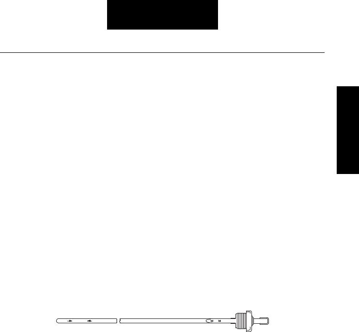
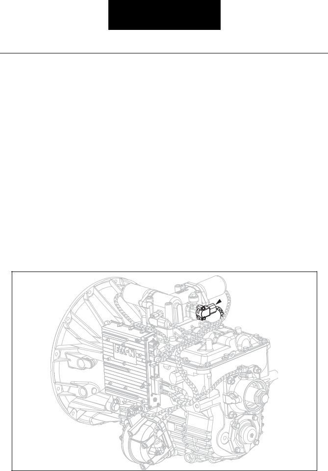
Checking WetClutch Lubricant
The WetClutch portion is checked using a dipstick located in the engine compartment.
Proper WetClutch Lubricant Level
WetClutch lubricant level should be checked when idling in neutral, with the transmission temperature between 60° F and 120° F (15.5° C and 48.8° C) and when the vehicle has been idling in neutral for at least two (2) minutes. Proper lubricant level is obtained when the lubricant is between the cold ADD mark and the cold FULL marks on the dipstick. Due to thermal expansion of the lubricant, it is not recommended to check the level when the transmission is above 120° F (48.8° C).
ADD COLD |
FULL |
(COLD 60-120 F) SYNTHETIC DEXRON III |
Checking Gearbox Lubricant
The gearbox portion is checked at the lubricant fill plug located on the right side of the gear case.
Information General
10
General Information
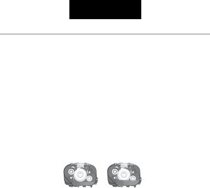
Proper Gearbox Lubricant Level
The gearbox lubricant is at the proper level when it is even with bottom of the fill hole. When you remove the plug to check the lubricant level, lubricant should seep out. Do not use your finger to feel for the lubricant. Even if you can touch the lubricant, it may not be at the proper level. In a transmission, one inch of lubricant level equals about one gallon of lubricant.
Hole |
Hole |
Improper Oil Level |
Proper Oil Level |
Inspect for Loose/Missing Bolts
While you are under the vehicle checking the lubricant, make a quick check for loose or missing bolts. Check all bolts on the PTO cover, inertia brake, shift bar housing, clutch housing oil pan, output flange, and transmission controller. Replace any missing or broken bolt with the proper bolts as called out in the illustrated parts listing. Follow the procedure defined in the transmission service manual when tightening any bolts.
Check for Lubricant Leaks
A lubricant leak could cause a catastrophic transmission failure. Check for leaks at the gasket surfaces, lubricant lines, flywheel housing, rear seal, and the cooler.
Gaskets
Visually check each gasket to ensure that no leak is present. Typically, a moist spot is acceptable, however, drips or larger wet areas are not. Check for leaks at the rear housing, PTO cover, shift bar housing, clutch housing to main case, inertia brake, and clutch oil pan. It is also important to ensure that the leak indeed is coming from the transmission. Make sure the lubricant is not being blown back from the engine or another vehicle component.
Lubricant Lines
There are three external lines for lubricant on the UltraShift HP transmission. One lubricates the inertia brake and the other two are for the oil cooler. Check the lines to ensure they are not leaking.
Flywheel Housing/Clutch Housing
Check for leaks around the flywheel housing/clutch housing mating surface. A faulty seal or loose fittings could cause leaks in the area. The UltraShift HP transmission has what is called a “wet housing” which means that the clutch housing is used as a sump for the WetClutch lubricant. Any leaks here could cause a transmission failure.
Transmission Cooler Leaks
11

General Information
Ensure there are no leaks at the lubricant cooler, hoses, and fittings of the cooler circuit.
Changing the Lubricant
When it is time to change the transmission lubricant, there are only a few steps to follow:
•Draining and Filling the WetClutch portion
•Draining and Filling the Gearbox portion,
•Draining and Filling the Cooler,
•Changing the Lubricant Filters
 WARNING
Remember to be careful when changing the transmission lubricant, as it may be hot.
Drain the Transmission Gearbox and WetClutch Housing
1.Locate the drain plugs at the bottom of the transmission gear case and on the clutch housing oil pan.
2.Place a drain pan under each drain plug.
3.Remove both drain plugs and allow the lubricants to drain completely.
4.Disconnect both cooler lines at the WetClutch housing.
5.Pressurize one line with 20 PSI until all lubricant is forced out of the cooler.
6.Reconnect both cooler lines.
Information General
12

General Information
Change WetClutch Filters
Change the lubricant filters when the transmission lubricant is changed. Detailed information can be found on removal and replacement of the oil filters in this service manual.
Fill the Transmission
1.Install the transmission gearbox drain plug and tighten to 45-55 lbs.ft. (61.0-74 N•m). Sealant is not required on the drain plug threads.
2.Install the clutch housing oil pan drain plug and torque to 34-48 lbs.ft. (46-65N•m). Sealant is not required on the drain plug thread.
3.Fill the transmission gearbox with the recommended lubricant until the lubricant seeps out of the fill hole.
4.Install the fill plug and torque to 25-35 lbs.ft. (34-47 N•m).
5.Slowly fill the clutch through the dipstick tube with a maximum of 18 pints (8.5 liters) of the recommended lubricant.
6.Place the transmission in neutral position and apply the parking brakes. Start the engine and let idle for five (5) minutes, (this allows oil to fill the WetClutch system and cooling system), add oil as needed to obtain a level at the proper temperature range. Total oil quantity should be approximately 24 pints: this varies depending on the cooling system capacity.
7.Increase the engine idle slowly to 1500 RPM for two (2) minutes. Next, recheck the oil level at normal idle speed in neutral, again adding oil to obtain a level at the proper temperature range.
8.Replace the dipstick and tighten securely.
Clutch Calibration
The UltraShift HP system automatically provides for clutch wear. The system will initiate a clutch calibration once per vehicle power up, when certain vehicle conditions are right. Of these conditions, the most important ones include: when the engine is running at idle speed, during normal operating temperature, when the vehicle is stopped, and when neutral is selected on the Shift Control. During the calibration, the clutch is partially engaged until the engine begins to slightly lug down. It will then disengage the clutch and repeat this process several times. The calibration process usually takes as little as thirty seconds but can take as long as two (2) minutes. The calibration will be aborted when any position other than neutral is selected on the Shift Control.
If it appears that the vehicle is not engaging smoothly from a stop, it is possible that the clutch needs to be re-cali- brated. If it has not been previously calibrated during the current power up, stop the vehicle with the engine idling at its normal operating temperature and place the Shift Control in neutral and wait two (2) minutes. If the calibration is being performed you should hear the engine slightly lug down and then return to its no load condition several times.
If calibration does not occur a Power Down/Power Up will initiate a calibration.
13

General Information
Oil Leak Inspection Process
|
|
|
|
|
|
|
|
Inspect for Oil Leak |
|
|
|
|
|
|||||
|
|
|
|
|
|
|
|
|
|
|
|
|
|
|
|
|
|
|
|
|
|
|
|
|
Determine if it is a Weep or a Leak |
|
|
|
|
|
|
||||||
|
|
|
|
|
|
|
|
|
|
|
|
|||||||
|
|
|
|
|
|
|
|
|
|
|
|
|
|
|
|
|
||
|
|
|
|
|
|
|
|
|
|
|
|
|
|
|
|
|||
Weep: Stained, damp, no drips, light oil film, |
|
|
|
|
Leak: Extremely wet or dripping of oil in the |
|||||||||||||
dirt adhered to the contaminated area. |
|
|
|
|
contaminated area. |
|||||||||||||
|
|
|
|
|
|
|
|
|
|
|
|
|
|
|
|
|
|
|
Gasket
1.Clean suspected oil weep area with a clean dry cloth or mild soluble degreaser.
2.Ensure lube is to proper level.
3.Notify the customer that it is only a weep and it is not considered to be detrimental to the life of the transmission.
4.Repair is complete.
Rear Seal
1.Do not repair: Rear seal is designed to allow minimal seepage (refer to Roadranger TCSM-0912 Seal Maintance Guide).
2.Ensure lube is to proper level.
Leak
Step 1
1.Determine the origin of the leak path.
2.If origin of leak is obvious skip to Step 3.
3.If the origin of the oil leak is not obvious then use either of the two following steps to determine the oil leak:
Note: Do not use a high pressure spray washer to clean the area. Use of a high pressure spray may force contamination into the area of concern and temporarily disrupt the leak path.
i.Clean area with a clean dry cloth or mild soluble degreaser and fill the transmission to the proper lube level.
OR
ii.Clean the area as noted above and insert tracer dye into the transmission lube and fill transmission to proper lube level.
Step 2
Operate vehicle to normal transmission operating temperature and inspect the area for oil leak(s) visually or if tracer dye was introduced use an UVL (Ultraviolet Light) to detect the tracer dye’s point of origin.
Note: When inspecting for the origin of the leak(s) make sure the assumed leak area is not being contaminated by a source either forward or above the identified area such as the engine, shift tower, shift bar housing, top mounted oil cooler, etc...
Step 3
Once the origin of the leak is identified, repair the oil leak using proper repair procedures from the designated model service manual.
Step 4
After the repair is completed, verify the leak is repaired and operate the vehicle to normal transmission operating temperature.
Inspect repaired area to ensure oil leak has been eliminated. If the leak(s) still occurs, repeat steps or contact the Roadranger Call Center at 1-800-826-4357.
Information General
14
Service Procedures
Lubricant Filter (UltraShift HP Models
Only) – Remove
Special Instructions
None
Required Tools
•Basic Hand Tools
Removal
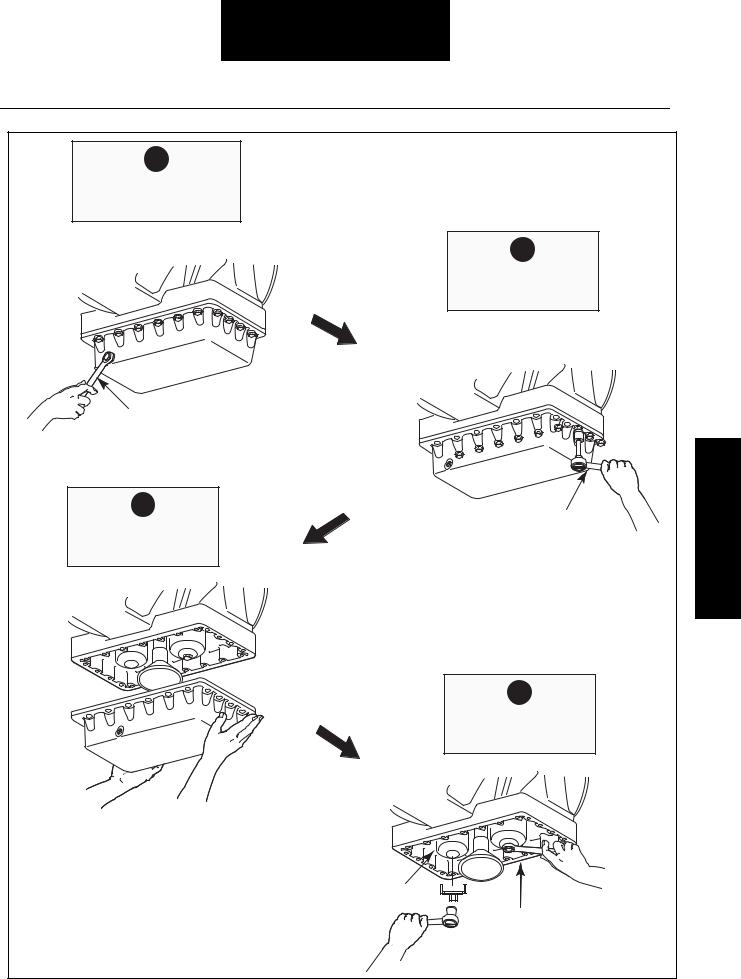
1.Remove the drain plug and drain the fluid from the WetClutch portion of the transmission.
 CAUTION
Fluid may be hot.
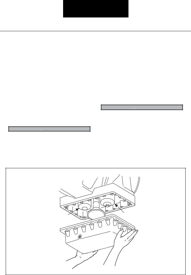
2.Using a 15mm wrench, remove the oil pan mounting bolts. Record location of the long and short bolts.
3.Remove the WetClutch oil pan and gasket.
4.Remove the two (2) WetClutch filters. Make sure filter seals are removed.
Note: The filters will contain fluid when they are removed.
 IMPORTANT
Transmission filters should be changed during regular lube intervals. Inspection of the transmission filter should be conducted during preventative maintenance checks for damage or corrosion. Replace as necessary.
Low Pressure Filter |
High Pressure Filter |
|
Filter Location
15
Service Procedures
1
Remove Drain Plug
Drain Fluid
2
Remove Oil Pan
Mounting Bolts
Wrench
3
15 mm Wrench
Remove Oil Pan
and Gasket
4
Remove Filters
Low Pressure Filter
High Pressure Filter
Procedures Service
Lubricant Filter Removal |
16 |
Service Procedures
Lubricant Filter (UltraShift HP Models
Only) – Install
Special Instructions
Install each filter in its correct location.
Clean filter seal mating surfaces on the transmission.
Clean and remove all old gasket material from the mating surfaces of the clutch housing and the oil pan.
Required Tools
Basic Hand Tools
Installation
1.Lubricate each filter seal ring with synthetic Dexron III prior to installation.
2.Install the low-pressure filter and turn until seal touches. Then tighten 3/4 to 1 full turn.
3.Install the high-pressure filter and tighten to 25-30 lbs.ft. (34-41 N•m).
4.Install a new gasket and the WetClutch oil pan.
5.Using a 15mm wrench install the mounting bolts and tighten to 30-35 lbs.ft. (41-47 N•m) using a cross pattern.
Note: Put the long and short bolts back in their proper location.
6.Install the oil pan drain plug and tighten to 34-48 lbs.ft. (46-65 N•m).
Note: Fill the WetClutch portion with the proper fluid.
Final Check
Make sure the bolts are properly tightened.
Make sure the WetClutch portion is properly filled with the specified fluid.
Check for fluid leaks during and after operating the vehicle.
 IMPORTANT
Transmission filters should be changed during regular lube intervals. Inspection of the transmission filter should be conducted during preventative maintenance checks for damage or corrosion. Replace as necessary.
17

Service Procedures
1 |
|
2 |
Lubricate Seal |
|
Install and Tighten |
Rings |
|
Low Pressure Filter |
Seal Ring |
|
|
|
Low Pressure Filter |
|
3 |
|
|
Install and Torque |
|
4 |
High Pressure Filter |
|
|
|
|
Install Oil Pan |
|
|
and Gasket |
|
|
Service |
High Pressure Filter |
Procedures |
|
|
Pan Gasket |
|
|
|
|
5 |
|
|
Install and Torque |
|
|
Mounting Bolts |
|
Oil Pan |
|
|
|
|
Torque Wrench |
|
Mouting Bolts |
6 |
|
|
Install and Torque |
|
|
Drain Plug |
Drain Plug |
|
|
Torque Wrench |
Lubricant Filter Installation |
18 |
Service Procedures
Rail Select Sensor – Remove
Special Instructions
While removing the hex key mounting screws, hold the sensor in place. Do not allow it to snap out of position.
Required Tools
•Basic Hand Tools
Removal
1.Disconnect the Transmission Harness from the Rail Select Sensor.
2.Using a 5/32” hex key wrench, remove the two (2) sensor hex key mounting screws.
Note: Carefully allow the sensor to rotate (not snap) to a relaxed position or the sensor can snap when the hex key mounting screws are removed.
3. Remove the sensor and gasket from the housing.
Rail Select
 Sensor
Rail Select Sensor Location
19
Service Procedures
1 |
|
|
Disconnect |
Transmission |
|
Harness |
||
Transmission Harness |
||
|
||
from Sensor |
|
Rail Select Sensor
2
Remove Hex Key Mounting Screws 
5/32"
Hex Key
Wrench
Rail Select Sensor
3
Remove
Sensor and Gasket
Rotate to
Relaxed Position
Gasket |
Hex Key |
|
Rail Select |
Mounting |
|
Sensor |
Screw |
120RMVRS |
|
Procedures Service
Rail Select Sensor Removal |
20 |

Service Procedures
Rail Select Sensor – Install
Special Instructions
While installing the hex key mounting screws, hold the Rail Select Sensor in place. Do not allow it to snap out of position.
Torques given below are in pound-inches. Use care not to overtighten.
Required Tools
Basic Hand Tools
Installation
1.Align the sensor’s tab with the slot in the shifter housing. Then insert the Rail Select Sensor, with gasket, into its mounting location.
Note: Install the sensor so the connector opening faces the right side of the transmission.
2.Using a 5/32" hex key wrench, install the hex key mounting screws and tighten to 21-27 lbs.in. (2.4- 3.1 N•m).
Note: Carefully hold the sensor in position while installing the hex key mounting screws or the sensor can snap.
3.Reconnect the Transmission Harness to the Rail Select Sensor.
Final Check
Make sure the gasket is installed between the sensor and the shifter housing.
Make sure the screws are tightened to specification.
Make sure all connections are tight.
Make sure the Transmission Harness is properly connected to the Gear Select Sensor.
Be sure to perform the Electric Shifter calibration procedure before operating the transmission.
21
Service Procedures
1
Insert Sensor and Gasket
Rotate to
Align Mounting
 Holes
Holes
Gasket |
Hex Key |
|
Mounting Screw |
Rail Select
Sensor
2
Install Hex Key Mounting Screws
5/32"
Hex Key
Wrench
Rail Select Sensor
3 |
Transmission Harness |
Reconnect
Transmission Harness
to Sensor
120INSRS
Rail Select Sensor
Procedures Service
Rail Select Sensor Installation |
22 |

Service Procedures
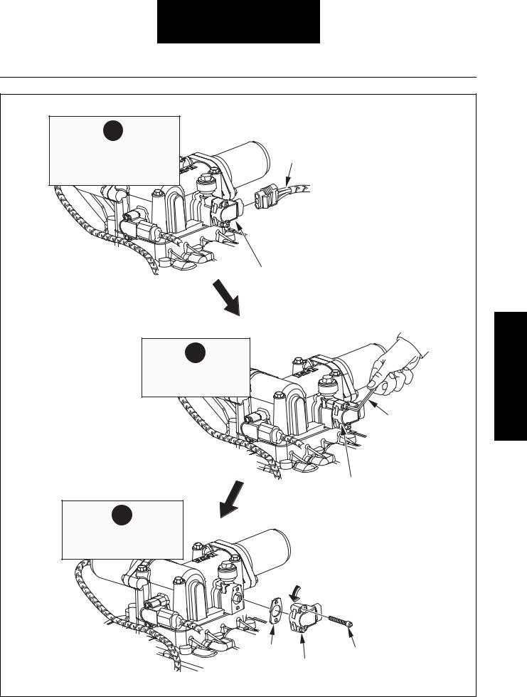
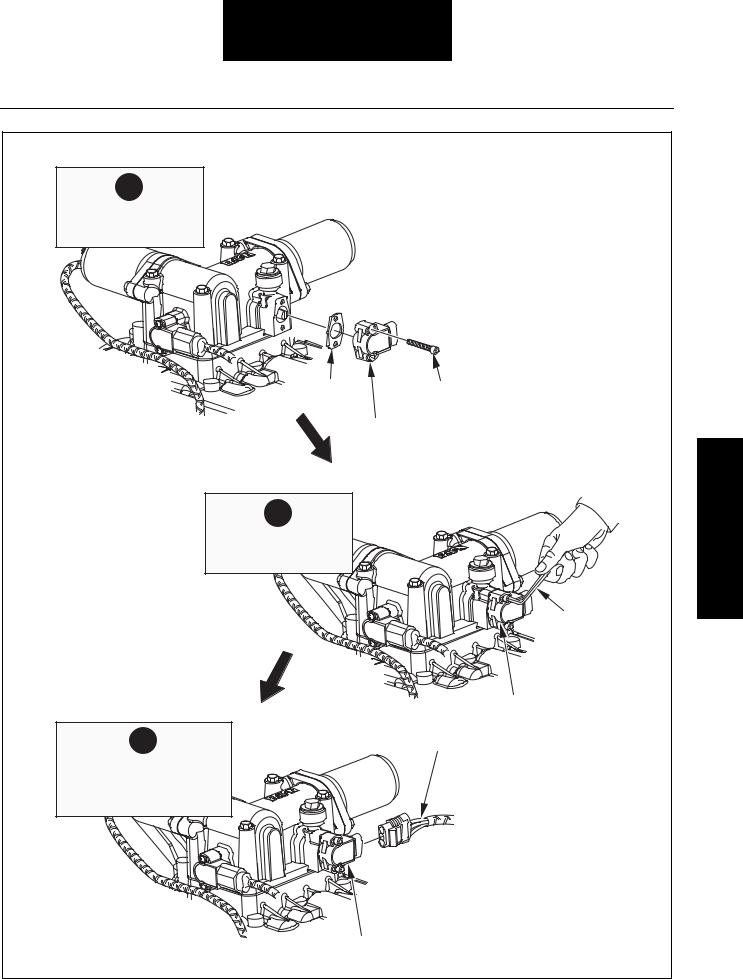
Gear Select Sensor – Remove
Special Instructions
While removing the hex key mounting screws, hold the sensor in place. Do not allow it to snap out of position.
Required Tools
Basic Hand Tools
Removal
1.Disconnect the Transmission Harness from the Gear Select Sensor.
2.Using a 5/32” hex key wrench, remove the two (2) sensor hex key mounting screws.
Note: Carefully allow the sensor to rotate to a relaxed position, or the sensor can snap when the hex key mounting screws are removed.
3. Remove the sensor and gasket from the housing.
Gear Select
Sensor
Gear Select Sensor Location
23
Service Procedures
1 |
|
|
|
Disconnect |
|
|
|
Transmission Harness |
|
|
|
from Sensor |
|
|
|
Gear Select |
|
|
2 |
Sensor |
Transmission |
|
|
|
|
|
|
|
Harness |
|
Remove Hex Key |
|
|
|
Mounting Screws |
|
5/32" |
|
Procedures Service |
|
Hex Key |
|
|
|
Wrench |
|
|
|
|
|
Gear Select |
|
|
|
Sensor |
Rotate to |
|
|
|
Relaxed Position |
|
|
|
|
|
3 |
|
Hex Key |
Gasket |
Remove |
|
Gear Select |
Sensor |
|
|
Mounting |
and Gasket |
120RMVGS |
|
|
|||
Screw |
Sensor |
|
|
|
|
||
Gear Select Sensor Removal |
24 |
Loading...